EP0156748A2 - Kombinierter Arbeitsplatz - Google Patents
Kombinierter Arbeitsplatz Download PDFInfo
- Publication number
- EP0156748A2 EP0156748A2 EP85420059A EP85420059A EP0156748A2 EP 0156748 A2 EP0156748 A2 EP 0156748A2 EP 85420059 A EP85420059 A EP 85420059A EP 85420059 A EP85420059 A EP 85420059A EP 0156748 A2 EP0156748 A2 EP 0156748A2
- Authority
- EP
- European Patent Office
- Prior art keywords
- uprights
- workstation according
- racks
- combined
- plate
- Prior art date
- Legal status (The legal status is an assumption and is not a legal conclusion. Google has not performed a legal analysis and makes no representation as to the accuracy of the status listed.)
- Withdrawn
Links
- 230000002787 reinforcement Effects 0.000 claims description 3
- 230000000630 rising effect Effects 0.000 claims description 2
- 238000012423 maintenance Methods 0.000 claims 1
- 230000001681 protective effect Effects 0.000 claims 1
- 230000006978 adaptation Effects 0.000 description 4
- 238000003860 storage Methods 0.000 description 4
- 238000013461 design Methods 0.000 description 3
- 238000011161 development Methods 0.000 description 3
- 230000008520 organization Effects 0.000 description 3
- 239000000470 constituent Substances 0.000 description 2
- 230000000694 effects Effects 0.000 description 2
- 238000005259 measurement Methods 0.000 description 2
- 239000002184 metal Substances 0.000 description 2
- 238000012986 modification Methods 0.000 description 2
- 230000004048 modification Effects 0.000 description 2
- 241000219504 Caryophyllales Species 0.000 description 1
- 230000005540 biological transmission Effects 0.000 description 1
- 239000012141 concentrate Substances 0.000 description 1
- 239000004020 conductor Substances 0.000 description 1
- 238000005520 cutting process Methods 0.000 description 1
- 230000003100 immobilizing effect Effects 0.000 description 1
- 238000009434 installation Methods 0.000 description 1
- 238000005304 joining Methods 0.000 description 1
- 238000004519 manufacturing process Methods 0.000 description 1
- 238000000034 method Methods 0.000 description 1
- 238000012544 monitoring process Methods 0.000 description 1
- 238000005192 partition Methods 0.000 description 1
- 238000012545 processing Methods 0.000 description 1
- 238000007493 shaping process Methods 0.000 description 1
- 230000009466 transformation Effects 0.000 description 1
- 238000003466 welding Methods 0.000 description 1
Images


Classifications
-
- A—HUMAN NECESSITIES
- A47—FURNITURE; DOMESTIC ARTICLES OR APPLIANCES; COFFEE MILLS; SPICE MILLS; SUCTION CLEANERS IN GENERAL
- A47B—TABLES; DESKS; OFFICE FURNITURE; CABINETS; DRAWERS; GENERAL DETAILS OF FURNITURE
- A47B21/00—Tables or desks for office equipment, e.g. typewriters, keyboards
- A47B21/02—Tables or desks for office equipment, e.g. typewriters, keyboards with vertical adjustable parts
-
- A—HUMAN NECESSITIES
- A47—FURNITURE; DOMESTIC ARTICLES OR APPLIANCES; COFFEE MILLS; SPICE MILLS; SUCTION CLEANERS IN GENERAL
- A47B—TABLES; DESKS; OFFICE FURNITURE; CABINETS; DRAWERS; GENERAL DETAILS OF FURNITURE
- A47B17/00—Writing-tables
- A47B17/03—Writing-tables with substantially horizontally extensible or adjustable parts other than drawers, e.g. leaves
-
- A—HUMAN NECESSITIES
- A47—FURNITURE; DOMESTIC ARTICLES OR APPLIANCES; COFFEE MILLS; SPICE MILLS; SUCTION CLEANERS IN GENERAL
- A47B—TABLES; DESKS; OFFICE FURNITURE; CABINETS; DRAWERS; GENERAL DETAILS OF FURNITURE
- A47B21/00—Tables or desks for office equipment, e.g. typewriters, keyboards
-
- A—HUMAN NECESSITIES
- A47—FURNITURE; DOMESTIC ARTICLES OR APPLIANCES; COFFEE MILLS; SPICE MILLS; SUCTION CLEANERS IN GENERAL
- A47B—TABLES; DESKS; OFFICE FURNITURE; CABINETS; DRAWERS; GENERAL DETAILS OF FURNITURE
- A47B37/00—Tables adapted for other particular purposes
Definitions
- such work stations are also designed so as to offer a grouping of worktops which can be directly used by an operator thus having, at his disposal, in a grouped manner and compact in volume, all the technical means having to be necessarily used to perform a given function or activity.
- such posts are constituted by a horizontal frame forming a base and from which rise two uprights having perforations or racks.
- the uprights are used to support overhanging trays which are fixed on consoles cooperating with the racks.
- the present invention aims to remedy the above drawbacks by proposing a new combined work station, particularly designed in a modular manner to allow adaptation according to the occupation of the premises or the work circuits to be respected.
- An additional object of the invention is to provide a new workstation, entirely removable, having the advantage of being able to be delivered flat, with the aim of significantly reducing the costs of transport and storage.
- An additional object of the invention is to provide a new combined work station constructed from constituent elements offering high mechanical strength and which can be produced at an attractive cost price.
- Another object of the invention is to propose a new workstation with the particularity of being able to be easily adapted to modifications or changes in working conditions, as well as to any temporary additional needs of an operator.
- Another object of the invention is to propose a new combined work station which can be combined with identical stations to create work installations combining a vertical and horizontal layout of the various supported working means.
- Yet another object of the invention resides in the fact that the combined work station according to the invention can be used for a station requiring the presence of at least one operator who must carry out monitoring of operations, surveillance, etc. in a sitting or standing position.
- Another object of the invention is to propose a new combined work station whose structure is particularly chosen to offer a great possibility of adaptation to the organization of computer work stations.
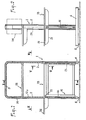
- Fig. 1 is a side elevation of the combined work station according to the invention.
- Figs. 2 and 3 are sections taken, respectively, along lines II-II and III-III of FIG. 1.
- Fig. 4 is a perspective, partially broken away, showing, on a larger scale, a detail of embodiment of one of the constituent elements of the combined work station.
- Fig. 5 is a partial cross-section, taken, on a larger scale, along the line V-V of FIG. 1.
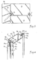
- Fig. 6 is a perspective showing a detail of embodiment of another element constituting the object of the invention.
- FIGs. 7 and 8 are partial perspectives illustrating two other provisions characteristic of the subject of the invention.
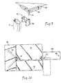
- Fig. 9 is a perspective of development.
- Fig. 10 is a plan view showing the advantage of the structure according to FIG. 9.
- the combined work station according to the invention illustrated in FIGS. 1 to 3, includes a support structure 1, in the form of a frame or vertical frame.
- This structure is constituted by two uprights 2 connected together by a hoop 3 removably joining their upper ends.
- the uprights 2 rise from two base legs 4 defining the support polygon of the vertical structure 1.
- the legs 4 can be provided with feet 5, possibly replaced by lockable rollers.
- each upright 2 is formed by the association of two identical sections 6a, 6b, with an open section substantially in "U" shape of small height.
- Fig. 4 shows that, according to a preferred arrangement, each open section comprises a core 7a or 7b whose length is equal to three or four times the height of the branches 8a which border it.
- the branches 8a or 8b are each extended by a wing 9a, 9b folded substantially square towards the outside to extend parallel to the core 7a.
- Each wing 9a, 9b has a semi- fallen end edge 10a, 10b, the function of which appears in the following.
- the open sections 6a and 6b are associated, so as to be placed face to face by the wings 9a and 9b, so as to delimit a general profile of closed rectangular tubular section.
- the sections 6a and 6b are assembled by weld points executed along the lateral areas formed by the wings 9a, 9b arranged side by side.
- the above structure has many technical advantages.
- First, the execution of the profile in the general sense is obtained by simple operations from metal strips which are then assembled after shaping. These operations are commonly carried out in most workshops with existing technical means and the production of such profiles can thus be ensured at a low cost price.
- the conformation of a tubular profile also has the advantage of giving a particularly high mechanical resistance, taking into account the different folds resulting from the conformation of the profiles 6a and 6b and the presence of the wings 9a, 9b.
- each upright 2 has in at least its sides parallel to the general plane of the structure 1, in this case the sides formed by the association of the branches 8a, 8b, at least two racks 12a, 12b formed over the entire length of the uprights.
- an upright 2 offers, on either side of each of its wings, two racks accessible from the two faces of the plane defined by the structure 1.
- the racks 12a and 12b are traditionally formed by the succession of elongated windows formed at constant intervals.
- each wing 9a, 9b also has a rack 13a, 13b formed in the part adjoining the branch 8a, 8b.
- the racks 13a, 13b are executed in coincidence with the racks 12a, 12b and the assembly of the sections 6a and 6b is carried out so that the racks 13a and 13b coincide with each other.
- the mode of execution of the uprights 2, from two sections 6a and 6b is also chosen, taking into account the presence of the racks, so that the latter can be easily executed by stamping-cutting operation on sheet metal strips. plane which are then shaped to give the section in open section. This makes it possible to obtain uprights 2 shaped and shaped at a low cost price.
- the uprights 2 are fixed by welding to the legs 4 and are connected by their open ends by the arch 3 having an identical structural conformation, except, possibly, the presence of the various racks.
- the arch 3 can be fitted by end caps 14 (fig. 1), possibly associated with removable immobilizing members. This characteristic makes it possible to constitute a structure 1 of variable width using different hoops 3 preferably having multiple or sub-multiples of one length. basic measurement.
- the structure 1 can also be composed, from uprights 2 of nominal height, extended by raising segments which are then joined by a hoop 3.
- the structure 2 thus has a possible modular character allowing the dimensional characteristics of the workstation to be adapted to the application for which it is intended.
- the uprights 2 are joined together in their end part rising from the legs 4 by a reinforcement frame 15 fixed by bolts.
- the frame 15 preferably comprises two vertical members 16, of tubular nature and the upper and lower ends of which are open.
- the members 16 can thus be used, where appropriate, for the passage and protection, at least locally, of conductors 17, for example of electrical supply.
- the vertical support structure 1 is intended to carry the work trays 18 extending in overhang from at least one of the sides of the structure 1.
- FIG. 2 shows that the uprights 2 of the structure rise from the middle zone of the legs 4, so that the support plates 18 can extend in cantilever, indifferently, from one of the any side of the structure or from both sides, without resulting in an imbalance of mass affecting the vertical stability of the workstation.
- Each plate 18 comprises, as is apparent from FIG. 5, a plate 19 fixed on the horizontal wings 20 of two brackets 21 each comprising a vertical wing 22.
- the connection between the plate 19 and the brackets 21 is carried out so that the vertical wings 22 extend beyond the edge 19a corresponding and thus project, externally to the latter, each two hooks 23 intended to cooperate with two windows of a rack 12a or 12b.
- the hooks 23 have a spacing corresponding to the pitch of the windows of the racks, so as to allow adaptation to any level of the amounts 2.
- each work plate 18 is constituted so that the wings 22 of the consoles 21 cooperate by the hooks 23 with the racks which can be considered as interior with respect to the structure 1, that is ie those formed in the branches 8a or 8b which define the interior periphery of the structure 1.
- the structure 1 can thus support several trays 18 with adjustable position, the measurement taken parallel to the structure can be equal to the latter, so that the combined workstation fits into a vertical parallelepiped volume of maximum size .
- the plates 18 are reserved for the support of various devices or represent work plans, mounting, etc.
- Figs. 1 and 2 show, in phantom, a possibility offered by the structure which has the characteristic of being only formed by a frame, without the presence of a central wall extending over the entire height of the uprights 2.
- This structural arrangement makes it possible to mount on the racks 12a or 12b, for example a chest or box 24, which can be used for storage, filing, storage, etc.
- the station according to the invention can be used for the work of a single operator using all of the trays extending on either side of the structure to support the apparatuses which he needs.
- the same workstation can be used by two operators facing each other, each using, for their needs, a determined number of adjustable trays extending from one of the faces of the plane defined by the structure 1.
- the uprights 2 can support a partial partition 25 adapted on one or the other of series of racks 12a, 12b.
- Fig. 6 shows that the plates tH can be constituted by a half-plate 26 occupying a fixed position and and by a half-plate 27 capable of being adjusted in relative spacing by removable fixing means, such as holes 28 , provided in the consoles 21.
- This makes it possible to delimit in a tray 18 a slot, passage or interval 29 allowing, for example, the vertical scrolling of a strip of paper feeding two independent processing devices carried by two trays 18 superimposed.
- the slides 13a and 13b, formed in the wings 9a and 9b can be used to ensure the association of two identical work stations, in order to constitute a modular assembly.
- two stations of the same conformation are placed in the same plane side by side by the uprights 2 which are connected by means of fishplates or keys 30 each having two slots 31 opening on the same longitudinal edge.
- Each splint 3U has a width equal to the length of the windows of the slides, so as to allow engagement in the direction of the arrow f ,, causing each splint 30 to cross, simultaneously, the wings 9a and 9b of the two uprights side by side .
- Each splint 3U is then lowered in the direction of the arrow f 2 to fit, by the notches 31, the lower edges of the engagement windows and thus relatively immobilize the two uprights 2 of two twin work stations.
- connection can be established by any number of fishplates 30 located at different levels from the uprights 2, when it is desired to make a framework of high mechanical strength.
- the racks 13a and 13b can also be used, as illustrated in FIG. 8, to allow the fitting of a fitting 32, with a "U" section, the branches of which have hooks 33 of the type of hooks 23 described above.
- the fitting 32 supports two consoles 34 extending in a divergent manner to ensure the fixing of a plate 35 illustrated in FIGS. 1 and 3.
- the assembly represents a work platform which can be adapted externally to the general overall size of the work station, extending in overhang relative to the amount considered.
- the assembly as described above, can be implemented simultaneously for the two transverse edges of a tray then making a connection between two identical work stations located at a distance from each other.
- Fig. 9 shows that the fitting 32 may include, instead of the brackets 34, a cylindrical bearing 36 with a vertical axis.
- the bearing 36 is intended for the establishment of a pivot 37 secured to a plate or bracket 38 attached under the underside of a plate 39, the dimensions of which may be any.
- the assembly of the plate 38 is carried out so that the pivot 37 is located near a corner of the plate.
- the plate 39 is preferably associated with a foot 40 provided with a fixed and steerable wheel.
- the station according to the invention consists of removable flat components which can be stored in a small space to reduce the volume of storage and transport.
Landscapes
- Assembled Shelves (AREA)
- Cultivation Receptacles Or Flower-Pots, Or Pots For Seedlings (AREA)
Applications Claiming Priority (2)
| Application Number | Priority Date | Filing Date | Title |
|---|---|---|---|
| FR8405266 | 1984-03-30 | ||
| FR8405266A FR2562208B1 (fr) | 1984-03-30 | 1984-03-30 | Postes de travail combines |
Publications (2)
| Publication Number | Publication Date |
|---|---|
| EP0156748A2 true EP0156748A2 (de) | 1985-10-02 |
| EP0156748A3 EP0156748A3 (de) | 1986-08-13 |
Family
ID=9302804
Family Applications (1)
| Application Number | Title | Priority Date | Filing Date |
|---|---|---|---|
| EP85420059A Withdrawn EP0156748A3 (de) | 1984-03-30 | 1985-03-27 | Kombinierter Arbeitsplatz |
Country Status (2)
| Country | Link |
|---|---|
| EP (1) | EP0156748A3 (de) |
| FR (1) | FR2562208B1 (de) |
Cited By (1)
| Publication number | Priority date | Publication date | Assignee | Title |
|---|---|---|---|---|
| US6792876B2 (en) * | 2002-08-21 | 2004-09-21 | Chin-Chih Lin | Tabletop suspension system |
Family Cites Families (5)
| Publication number | Priority date | Publication date | Assignee | Title |
|---|---|---|---|---|
| CH178178A (de) * | 1934-11-29 | 1935-07-15 | O Haberfeld Erwin | Traggestell für Schreibgeräte, Karteikästen und dergleichen. |
| FR1064615A (fr) * | 1949-06-24 | 1954-05-17 | Montant de rayonnage à tablettes mobiles guidées | |
| FR2109129A5 (de) * | 1970-10-02 | 1972-05-26 | Vincens Rene | |
| US3922045A (en) * | 1973-11-12 | 1975-11-25 | Lawrence F Meyer | Modular structure |
| FR2348673A1 (fr) * | 1976-04-21 | 1977-11-18 | Habilclass Sa | Meuble support pour l'equipement de comptoirs de lieux publics |
-
1984
- 1984-03-30 FR FR8405266A patent/FR2562208B1/fr not_active Expired
-
1985
- 1985-03-27 EP EP85420059A patent/EP0156748A3/de not_active Withdrawn
Cited By (1)
| Publication number | Priority date | Publication date | Assignee | Title |
|---|---|---|---|---|
| US6792876B2 (en) * | 2002-08-21 | 2004-09-21 | Chin-Chih Lin | Tabletop suspension system |
Also Published As
| Publication number | Publication date |
|---|---|
| EP0156748A3 (de) | 1986-08-13 |
| FR2562208B1 (fr) | 1987-08-07 |
| FR2562208A1 (fr) | 1985-10-04 |
Similar Documents
| Publication | Publication Date | Title |
|---|---|---|
| EP0642754A1 (de) | Schaukastenrückwand und Schaukasten mit einer solchen Rückwand | |
| FR2799901A1 (fr) | Element support pour cablage et enceinte d'equipement associee | |
| EP0517617A1 (de) | Modulare Regale | |
| WO2000003147A1 (fr) | Meuble comportant un ensemble d'elements rigides assembles | |
| BE1011814A4 (fr) | Element de separation en forme de panneau pour realiser des cloisons et presentoirs pour des manifestations temporaires. | |
| EP0123614A1 (de) | Kartei mit schrägen Ablageflächen | |
| EP0156748A2 (de) | Kombinierter Arbeitsplatz | |
| EP0261012B1 (de) | Ordnungs- oder Transportvorrichtung für Gegenstände oder verschiedene Produkte | |
| FR2634637A1 (fr) | Procede de fabrication d'un panneau de support formant presentoir, et panneau obtenu par la mise en oeuvre de ce procede | |
| FR2462124A1 (fr) | Table support a colonne centrale et deux niveaux | |
| FR2647328A1 (fr) | Presentoir pour bouteilles | |
| FR2596718A1 (fr) | Socle pour chariot de manutention | |
| EP0212996A2 (de) | Elementensatz für die Einrichtung von Ausstellungsräumen, Geschäften und anderen Orten | |
| EP4470725B1 (de) | Modulare speicheranordnung | |
| FR2638345A1 (fr) | Dispositif de rangement et de presentation, notamment pour magasins de detail | |
| FR2575052A1 (fr) | Dispositif destine a equiper un presentoir, ou similaire, pour servir de support a une serie de tiges de suspension d'articles divers, et meubles presentoirs equipes d'un tel dispositif | |
| FR2569091A3 (fr) | Table allongeable et demontage | |
| FR3101088A1 (fr) | Echafaudage | |
| FR2717058A1 (fr) | Table modulable. | |
| FR2619295A1 (fr) | Ratelier pour outils aratoires | |
| EP1616501B1 (de) | Büromöbel mit konfigurierbarem Untergestell | |
| FR3147940A3 (fr) | Meuble de rangement modulaire | |
| EP3123900A1 (de) | Möbelstück zum zusammenbau ohne kleber oder schrauben | |
| FR2874487A1 (fr) | Panneau de fond pour mobilier metallique de rayonnages | |
| FR2584041A1 (fr) | Rayonnage repliable pour chariot de manutention |
Legal Events
| Date | Code | Title | Description |
|---|---|---|---|
| PUAI | Public reference made under article 153(3) epc to a published international application that has entered the european phase |
Free format text: ORIGINAL CODE: 0009012 |
|
| AK | Designated contracting states |
Designated state(s): DE FR GB IT |
|
| PUAL | Search report despatched |
Free format text: ORIGINAL CODE: 0009013 |
|
| AK | Designated contracting states |
Kind code of ref document: A3 Designated state(s): DE FR GB IT |
|
| 17P | Request for examination filed |
Effective date: 19861008 |
|
| 17Q | First examination report despatched |
Effective date: 19880630 |
|
| STAA | Information on the status of an ep patent application or granted ep patent |
Free format text: STATUS: THE APPLICATION IS DEEMED TO BE WITHDRAWN |
|
| 18D | Application deemed to be withdrawn |
Effective date: 19890511 |
|
| RIN1 | Information on inventor provided before grant (corrected) |
Inventor name: BOYER, ROBERT Inventor name: BOREL, FRANCOIS Inventor name: TOURRE, RAYMOND |