EP0156870B1 - Arrangement for the manufacture of an elongated organ - Google Patents
Arrangement for the manufacture of an elongated organ Download PDFInfo
- Publication number
- EP0156870B1 EP0156870B1 EP84903567A EP84903567A EP0156870B1 EP 0156870 B1 EP0156870 B1 EP 0156870B1 EP 84903567 A EP84903567 A EP 84903567A EP 84903567 A EP84903567 A EP 84903567A EP 0156870 B1 EP0156870 B1 EP 0156870B1
- Authority
- EP
- European Patent Office
- Prior art keywords
- matrix
- compression
- compression chamber
- arrangement
- section
- Prior art date
- Legal status (The legal status is an assumption and is not a legal conclusion. Google has not performed a legal analysis and makes no representation as to the accuracy of the status listed.)
- Expired
Links
- 238000004519 manufacturing process Methods 0.000 title abstract description 20
- 210000000056 organ Anatomy 0.000 title abstract description 5
- 230000006835 compression Effects 0.000 claims abstract description 62
- 238000007906 compression Methods 0.000 claims abstract description 62
- 239000000463 material Substances 0.000 claims abstract description 45
- 239000011810 insulating material Substances 0.000 claims abstract description 9
- 239000005388 borosilicate glass Substances 0.000 claims abstract description 3
- 239000002657 fibrous material Substances 0.000 claims description 39
- 239000011159 matrix material Substances 0.000 claims description 30
- 238000006073 displacement reaction Methods 0.000 claims description 19
- 238000010438 heat treatment Methods 0.000 claims description 18
- 239000011230 binding agent Substances 0.000 claims description 16
- 230000003014 reinforcing effect Effects 0.000 claims description 13
- 239000012777 electrically insulating material Substances 0.000 claims description 5
- 230000003534 oscillatory effect Effects 0.000 claims description 3
- 230000009471 action Effects 0.000 claims description 2
- 238000001035 drying Methods 0.000 claims 1
- 230000002708 enhancing effect Effects 0.000 claims 1
- 239000007767 bonding agent Substances 0.000 abstract description 9
- 238000005452 bending Methods 0.000 description 5
- 238000000034 method Methods 0.000 description 5
- 230000008569 process Effects 0.000 description 4
- 125000006850 spacer group Chemical group 0.000 description 4
- 239000000853 adhesive Substances 0.000 description 3
- 230000001070 adhesive effect Effects 0.000 description 3
- 238000010276 construction Methods 0.000 description 3
- XEEYBQQBJWHFJM-UHFFFAOYSA-N iron Substances [Fe] XEEYBQQBJWHFJM-UHFFFAOYSA-N 0.000 description 3
- 239000000725 suspension Substances 0.000 description 3
- 239000002023 wood Substances 0.000 description 3
- 239000000470 constituent Substances 0.000 description 2
- 230000001747 exhibiting effect Effects 0.000 description 2
- 229910052742 iron Inorganic materials 0.000 description 2
- 238000012986 modification Methods 0.000 description 2
- 230000004048 modification Effects 0.000 description 2
- 239000004033 plastic Substances 0.000 description 2
- 229920003023 plastic Polymers 0.000 description 2
- 230000002787 reinforcement Effects 0.000 description 2
- 239000003351 stiffener Substances 0.000 description 2
- 241000969130 Atthis Species 0.000 description 1
- 229920002522 Wood fibre Polymers 0.000 description 1
- 230000004913 activation Effects 0.000 description 1
- 239000011248 coating agent Substances 0.000 description 1
- 238000000576 coating method Methods 0.000 description 1
- 230000008878 coupling Effects 0.000 description 1
- 238000010168 coupling process Methods 0.000 description 1
- 238000005859 coupling reaction Methods 0.000 description 1
- 238000005520 cutting process Methods 0.000 description 1
- 230000001419 dependent effect Effects 0.000 description 1
- 238000009826 distribution Methods 0.000 description 1
- 230000000694 effects Effects 0.000 description 1
- 238000010292 electrical insulation Methods 0.000 description 1
- 239000011152 fibreglass Substances 0.000 description 1
- 239000003365 glass fiber Substances 0.000 description 1
- 238000009413 insulation Methods 0.000 description 1
- 239000007788 liquid Substances 0.000 description 1
- 239000000203 mixture Substances 0.000 description 1
- 239000003973 paint Substances 0.000 description 1
- 239000010893 paper waste Substances 0.000 description 1
- 239000007858 starting material Substances 0.000 description 1
- 239000002966 varnish Substances 0.000 description 1
Images

Classifications
-
- B—PERFORMING OPERATIONS; TRANSPORTING
- B27—WORKING OR PRESERVING WOOD OR SIMILAR MATERIAL; NAILING OR STAPLING MACHINES IN GENERAL
- B27N—MANUFACTURE BY DRY PROCESSES OF ARTICLES, WITH OR WITHOUT ORGANIC BINDING AGENTS, MADE FROM PARTICLES OR FIBRES CONSISTING OF WOOD OR OTHER LIGNOCELLULOSIC OR LIKE ORGANIC MATERIAL
- B27N5/00—Manufacture of non-flat articles
-
- B—PERFORMING OPERATIONS; TRANSPORTING
- B27—WORKING OR PRESERVING WOOD OR SIMILAR MATERIAL; NAILING OR STAPLING MACHINES IN GENERAL
- B27N—MANUFACTURE BY DRY PROCESSES OF ARTICLES, WITH OR WITHOUT ORGANIC BINDING AGENTS, MADE FROM PARTICLES OR FIBRES CONSISTING OF WOOD OR OTHER LIGNOCELLULOSIC OR LIKE ORGANIC MATERIAL
- B27N7/00—After-treatment, e.g. reducing swelling or shrinkage, surfacing; Protecting the edges of boards against access of humidity
-
- B—PERFORMING OPERATIONS; TRANSPORTING
- B29—WORKING OF PLASTICS; WORKING OF SUBSTANCES IN A PLASTIC STATE IN GENERAL
- B29C—SHAPING OR JOINING OF PLASTICS; SHAPING OF MATERIAL IN A PLASTIC STATE, NOT OTHERWISE PROVIDED FOR; AFTER-TREATMENT OF THE SHAPED PRODUCTS, e.g. REPAIRING
- B29C35/00—Heating, cooling or curing, e.g. crosslinking or vulcanising; Apparatus therefor
- B29C35/02—Heating or curing, e.g. crosslinking or vulcanizing during moulding, e.g. in a mould
- B29C35/12—Dielectric heating
- B29C35/14—Dielectric heating for articles of indefinite length
-
- B—PERFORMING OPERATIONS; TRANSPORTING
- B29—WORKING OF PLASTICS; WORKING OF SUBSTANCES IN A PLASTIC STATE IN GENERAL
- B29K—INDEXING SCHEME ASSOCIATED WITH SUBCLASSES B29B, B29C OR B29D, RELATING TO MOULDING MATERIALS OR TO MATERIALS FOR MOULDS, REINFORCEMENTS, FILLERS OR PREFORMED PARTS, e.g. INSERTS
- B29K2503/00—Use of resin-bonded materials as filler
Definitions
- the present invention relates to an apparatus for producing an elongate element in which a compression arrangement is so executed and arranged as to displace and compress a quantity of material moistened with a bonding agent.
- the apparatus comprises a compression chamber equipped with compressing means, and the fibrous material required to produce the elongated element is introduced into the compression chamber in batches, or all at once.
- the compressing means are arranged to first subject the fibrous material to compression forces, and to then move the fibrous material through a matrix, whereafter the compressing means are returned and moved out of the compression chamber, which is then filled with a further batch of fibrous material, this further batch then being compressed and displaced along the matrix by the compressing means.
- the present invention can be applied both in the manufacture of an elongate element having incorporated therein reinforcing rods, bands, wires or like stiffeners, which increase the bending resistance of the element, and also in the manufacture of an elongated element which lacks the inclusion of such stiffeners.
- the starting material used to produce the elongate element either comprises a fibre-suspension to which a binder has been added, where the suspension is compressed and then cured to produce a finished element, or a fibrous material which is sprayed or moistened with a binder and the material is then subjected to pressure and cured, to form the finished element.
- a compression arrangement is also so arranged as to displace and compress a quantity of material moistened with a bonding agent, in particular an adhesive.
- German Offen- legungsschrift 1 019 951 is previously disclosed a method of manufacturing an elongate element by causing a portion of the total quantity of the fibrous material intended for the entire element to be introduced into a compression chamber where the portion is compressed by a compressing means.
- the compressing means is capable of then being caused to move out of the compression chamber so that a new portion of the fibrous material can be introduced into the compression chamber, which is then compressed once more.
- Swedish Patent Specification 416 718 is an arrangement for the manufacture of an elongate element or product by the compression of a fibrous material to which a bonding agent has been added, in such a way that a portion of the total quantity of the fibrous material, intended for the entire element, can be placed inside a compression chamber with a compressing means.
- the compressing means is so activated as first to apply compressive force to the portion followed by its displacement into a mould and then to move in the opposite direction and to be removed from the compression chamber, which can then be filled once more with a portion of the fibrous material.
- the new portion is itself compressed and displaced by the compressing means.
- the mould shall be so executed as to exhibit a number of wall parts, all of which are caused to move relative to the element, said relative movement occurring in the longitudinal and/or production sense of the element.
- a particularly challenging technical problem also arises, in the case of a heated section which utilizes high frequency, in conjunction with the implementation of measures such that the constituent component parts of the heated section will not short-circuit the high frequency, and yet will still be capable of forming a sufficiently stable wall part to withstand the pressure which occurs, in particular at the mouth of the heated section, and for it also to serve as a compression chamber.
- a further problem also arises in conjunction with the creation of conditions such that the moisture released by the curing process in the heated section can be conducted away from the material.
- a further problem also arises, in the case of a heated section which utilizes high frequency, in conjunction with the implementation of measures such that short-circuiting will not occur between high-frequency components executed within the heated section and in particular those components which form part of the compression arrangement and a metering unit or via a pistion incorporating the compression arrangement.
- a further problem also arises in conjunction with the creation of conditions such that the wall parts of the heated section can be so arranged as to be capable of displacement in the direction of displacement of the compressed portions of the material, in so doing creating conditions such that, when the portion of material and the Wall parts have been introduced into a position approximating to that of the compression arrangement, then either all, or in any event two or three of the wall parts will be capable of simultaneous displacement over a certain distance in a direction away from the compression arrangement, but with the wall parts necessarily remaining capable of subsequent individual displacement in the opposite direction.
- Still another problem is one of constructing the compression chamber from simple components and to provide means which generate limited friction when the elongated element is moved along the matrix, and also to provide means which will impart a good surface finish to the outer surface of the elongated element.
- Another problem is one of removing from the matrix, in a simple fashion, moisture created during the heat-treatment process, solely through the design of the structural components forming the matrix.
- Another problem is one of providng means which enable a reinforcing band wire or like stiffening element which will increase the mechanical strength of a finished elongated element to be passed through the compression chamber and the compressing means.
- Another problem is one of providing a heating a curing station in which curing of the elongated element, preferably from the centre and outwards, can be effected rapidly.
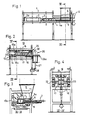
- FIG. 1 Illustrated with reference to Figure 1 is a first section of a production line for an arrangement or apparatus for the manufacture of an elongate element. This section continues as the second section illustrated in Figure 2.
- FIG. 1 a frame intended for the arrangement has been allocated the reference designation 1.
- the frame 1 has been simplified somewhat in the interests of clarity, but exhibits all details necessary to be able to appreciate all the constituent parts.
- a control device of in itself simple construction provided for the purpose of controlling in a certain sequence the hydraulic piston and hydraulic cylinder devices illustrated in the arrangement, which are also capable of pneumatic operation if necessary.
- Illustrated in Figure 1 is the manner in which a cylinder 2 is securely attached at the point 2a to the frame and the manner in which its piston (not shown) and the piston rod 3 attached to it is securely attached to a long rod 4.
- Actuation of the cylinder 2 will cause the piston rod 3 and its associated piston to impart to the rod 4 a displacement to the right in Figure 1.
- the arrangement 5 may be so executed at its upper part as to exhibit a space for fibrous material (wood fibre material) and a space for a bonding agent (an adhesive), and with the help of a mixing station (not shown in the figure), the fibrous material and the bonding agent are mixed in pre-determined proportions and are fed into a pocket forming part of the arrangement 5.
- the arrangement 5, which is illustrated more clearly in Figure 3, is in the form of a funnel, the lower part 5a of which interacts with a metering arrangement.
- a piston 11 With the help of a piston 11, a cylinder 7 with an associated piston and piston rod 8 a portion of material can be displaced from the lower part of the funnel into a space 9.
- the space 9 is defined by four wall parts, with the wall parts 10, 10a and 10b being fixed, and the wall part 10c being the front end of the piston 11.
- the portion of material which has been displaced out and into the space 9 will now have been compressed slightly ahead of the front end 4a of the rod 4 illustrated in Figure 1.
- the rod 4 will then return to the position shown in Figure 1, and during the cycle in which the portion of material is filled into the space 9 the wall parts 15, 16, 17 and 18 will be displaced individually back to a position in which the end surfaces 15a, 16a are located adjacent to the unit 13, in so doing providing wall parts for the compression chamber.
- FIG. 4 Illustrated with particular reference to Figure 4 is the manner in which the compressed portion of material 20 is caused to pass through a heated section 19 operating at high frequency.
- Figure 4 shows here that the portions of material 20 are given an essentially rectangular section, although it is obvious that other sections can occur.
- the two opposing wall parts 15,16 in the heated section 19 constitute parts of an in itself known high-frequency apparatus, which is not described here in any greater detail for that reason.
- the two opposing side parts 17 and 18 consist of insulating material, and the expression insulating material is used in this context primarily to denote a material which does not impair the high-frequency effect on the portion of material 20.
- a piston or rod 4 containing the compression arrangement consists fully, or in this case in part, of such insulating material. More specifically, its front part 4a must, of course, consist of such electrically insulating material.
- the present invention also relates to an apparatus in which all the wall parts 15,16,17 and 18 of the heated section 19, or only some of them, are so arranged as to be capable of displacement in the direction of displacement of the compressed portions of material.
- the movable wall parts are capable of simultaneous displacement in a direction away from the unit 13 and over a certain distance from the formed compression arrangement together with the rod 4, whereas subsequently, once the rod 4 has returned to its position as indicated in Figure 1, the displacement of each of the individual movable wall parts will occur in sequence in the opposite direction.
- the wall part 15 interacts with a hydraulic cylinder with an enclosed piston 21
- the wall part 16 is shown to be fixed, the wall part 17 with a hydraulic cylinder with an enclosed piston 22 and the wall part 18 with a hydraulic cylinder with an enclosed piston 23.
- the reason for causing the wall parts to be displaced individually in the opposite direction is that the friction between the wall parts and the material 20 is reduced in this way to such an extent that the material 20 will not accompany said displacement.
- the wall parts 15, 16, 17, 18 or, in this instance, three of these shall be so arranged as to diverge in a direction away from the compression arrangement or the unit 13 in order to conduct any moisture contained in the portion of material 20 away from the heated section 19.
- a cutting device 26 driven by a motor 26a and capable of up-and- down adjustment via a rod 27 and a drive arrangement 28, the cutter wheels 30 of which are so arranged as to cut the elongate organ into lengths, in this way producing components for pallets.
- Figure 5 is a side-elevation view illustrating very simply an apparatus 101 for producing an elongate element 104 in accordance with the present invention.
- the illustrated apparatus includes a hydraulic piston-cylinder device 110 with associated piston and piston rod 109.
- the piston rod is reciprocatingly movable and co-acts with a compressing means 108 having the form of a ram and projecting slightly into the compression chamber 107, to form a part thereof, namely a rearward wall section of said chamber.
- a feed means 106 Located immediately above the compression chamber 107 is a feed means 106.
- the feed means 106 may have a compartment for fibrous material and a compartment for binding agent.
- the fibrous material and the binding agent are mixed together in a mixing station (not shown), in given quantities, and discharged to a lower space 106a, from where a batch of the total amount of fibrous material required to form a complete elongate element 104 is fed via metering means not shown in Figure 1.
- the elongate element can, of course, be formed from a fibrous material moistened or sprayed with a binding agent, in which case in particular the material can be fed directly to the compression chamber 107 and there placed under pressure.
- the material may comprise wood shavings, waste-paper, plastics, wood-chips and like material.
- the piston-like compressing means 108 is moved reciprocatingly by the aforesaid hydraulic piston-cylinder device 110 with associated piston and piston rod 109.
- the compressing means 108 is shown in side elevation in a non- compressing, withdrawn position, in which the compression chamber is free to receive said fibrous material. With the compressing means 108 located in this position, the space in front of the compressing means is filled with fibrous material from the feed means 106. This is made possible because, as the compressing means 108 is withdrawn to the illutrated position, it exposes an opening through which said space, or the compression chamber, can be filled.
- the compressing means 108 When the compressing means 108 is moved to the right in Figure 5, the fibrous material, or said batch of material, in the compression chamber is compressed against the preceding batch of fibrous material metered to the compression chamber, so as to form a part or section of the whole of the intended element.
- the elongate element are formed by compression in the compression chamber 107 and then moved, as a unit, via a matrix to a heating section 105.
- the compressed fibrous material provided with binding agent is introduced to the heating section through the end-part 105a thereof, and is there subjected to heat treatment in a conventional high-frequency station, not shown in detail, whereafter the finished elongate element is discharged from the heating section, through the end-part 105b thereof.
- the finished elongate element is referenced 104 in Figure 5.
- the elongate element 104 can be passed from the heating section 105 directly to a treatment station 103, for coating the outer surfaces of said element with an impregnating liquid, paint, varnish or the like.
- the reference 102 identifies a symbolically illustrated control means for controlling the activation of the compressing means 108, the metering of the fibrous material and binding agent together with the quantities in which they are dispensed; the feed means 106 containing the fibrous material; press means; and the functions of other means incorporated in the apparatus 101.
- the various control components associated with the control means 102 have not been specifically shown or described, the structural design of said control components will be readily understood from the following description of the operational mode of the apparatus.
- Figure 6 illustrates in more detail an apparatus according to the invention for producing an elongate element 104, more specifically two mutually parallel elements 104a, 104b, said elements being formed by compressing fibrous material provided with bonding agent, in a space 111 formed in the compression chamber 107.
- a controlled, given quantity of fibrous material provided with binding agent is charged to the space 111 in the compression chamber 107 by means not shown in the Figure, and is there compressed by means of compressing means, here referenced 108a.
- the compressing means 108a is advanced by means of the hydraulic piston-cylinder device, the piston rod 109 of which co-acts with a beam 109a rigidly connected to the compressing means 108a, so as not to bend.
- the apparatus illustrated in Figure 6 is intended to produce two elongate elements simultaneously, and therefore includes a further beam 109b and a further compressing means or ram 108b driven by the piston-cylinder device 110.
- a further beam 109b and a further compressing means or ram 108b driven by the piston-cylinder device 110.
- the beam 109b and ram 108b are identical with the beam 109a and the ram 108a, the beam and ram 109b and 108b respectively will not be described further.
- the compressing means 108 When the compressing means 108 is moved to the right in Figure 6, the fibrous material present in the space 111 is first compressed and then moved along a matrix 112. Upon completion of its working stroke, the compression means 108a is withdrawn, out of the compression chamber 107, to expose the space 111 and to enable a further batch of fibrous material to be fed thereinto, this further batch of material then being compressed and displaced by the compressing means 108a.
- the matrix 112 comprises a plurality of wall sections, of which at least some are arranged for movement relative to the elongate element, this relative movement preferably taking place in the direction of the longitudinal axis of the elongate element or the matrix, or in the direction in which the element is formed.
- the fibrous-material sections formed by the compressing means 108a and containing binding agent are now arranged one after the other, and pass in the form of a single unit through the matrix and are there subjected to heat treatment, with the aid of high-frequency heating means, not shown in Figure 6, located in the proximity of the compression chamber 107.
- the matrix comprises two mutually superposed and mutually parallel electrically conductive plates, of which the upper is referenced 113 and the lower is referenced 114.
- electrically insulated spacers Arranged between the plates 113 and 114 are electrically insulated spacers, which comprise a plurality of mutually parallel matrix sections 115, 116, 117, the ends 115a, 116a, 117a, of which are connected together by means of an electrically insultated beam 118.
- the beam 118 is connected to the piston rod 119 of a hydraulic piston-cylinder device 120.
- the two electrically conducted plates are preferably arranged for movement axially, conveniently with the axial movement of respective plates being out of phase with respect to one another.
- the plate 113 can be arranged to move in the direction of the arrows »P1» while the plate 114 is arranged for movement in the direction of the arrows »P2».
- This movement of the plates can be effected by means of hydraulic piston-cylinder devices, not shown, with associated piston rods, also not shown, and controlled through the control means 12.
- the plate 114 may also be convenient to permit at least the plate 114 to accompany the movement of the compressing means 108a to the right in Figure 6, while holding the plate 113 stationary.
- the compressing means 108a When the compressing means 108a has completed its working stroke, or when the leading edge 108a' of said means has passed through the space 111, beyond the edge 111a, it may be suitable to cause the upper plate 113 to carry out a corresponding movement, whereafter the plate 113 is returned to the position illustrated in Figure 6 and the compressing means 108a, together with the plate 114, then moved back to the position shown in Figure 6.
- the matrix sections 115, 116, 117 form a unit and can be caused to move in an oscillatory fashion, by means of the hydraulic piston-cylinder device 120. In all events, it is proposed that the matrix sections are moved via the device 120, backwards and forwards at a frequency which is greater than the frequency at which the plates 113 and 114 are moved. The ratio should be 5-20 times.
- FIG. 7 illustrates in a simplified manner a compressing means 108a intended for producing an elongate element which has embedded therein reinforcing bands which increase the bending resistance of the element, and which can be used as a structural member in the manufacture of door frames.
- the compressing means 108a is provided with two, mutually parallel slots 121, 122, into each of which there is inserted a respective reinforcing band 123 and 124, which may be made of a fibre-glass material for example.
- the band 123 is taken from a reel 125, while the band 124 is taken from a reel 126, the bands preferably being taken from respective reels against the action of a friction coupling, not shown.
- Figure 8 is a sectional view of a matrix in an apparatus in which two elongate elements intended to form the structural members of a door frame are produced.
- the figure illustrates the aforementioned two mutually parallel plates 113 and 114 and the spacers 115, 116 and 117, where the latter have been given a configuration corresponding to the form of the door frame.
- the surfaces of the spacers 115, 116, 117 facing the plate 114 are provided with grooves 130,131,132, and 133, while the surfaces of the spacers facing the plate 113 are provided with grooves 134, 135 and 136.
- the elongate element 104a and the elongate element 104b may optionally be provided with a respective recess 140, 141, as illustrated, so as to decrease the amount of fibrous material required in their manufacture.
- the stiffening bands 123, 124 can be located in those places in the elongate elements where reinforcement is desired.
- a reinforcing strap, rod or like stiffening means 123, 124 capable of increasing the bending resistance of the element is preferably passed through the compression chamber and through the compression means, and at least one of such band is pre-tensioned, to compensate for the calculated internal stresses.
- FIG. 9 is a sectional view of an alternative compression chamber and compression means.
- the bands 123, 124 are used to reinforce the manufactured elongate element 104.
- a metering device or dispensing fibrous material provided with a binding agent comprises a plurality of working pistons or rams 151, 152, 153 with intermediate wall sections 154, 155, where the fibrous material is pressed down into the space 111 formed in the compression chamber 107.
- the lower portions of the wall sections 154, 155 are provided with guards 156, 157, which are effective to prevent fibrous material fed into the space 111 from acting downwardly on the bands 123, 124 in a manner to dislodge same, so the the bands remain in their selected positions.
- the wall sections 154 and 155 may be arranged for vertical movement, so that they can be raised and lowered.
- Figure 10 illustrates in perspective part of the matrix 112, from which figure it can be seen that arranged in the upper surface of the matrix section 115 is a slot 133, while a similar slot 134 is provided in the upper surface of the matrix section 116.
- These slots 133 and 134 are connected to a suction means (not shown) for removal of moisture released from the fibrous material during the heat-treatment process.
- means are provided for lifting the ptate 113 slightly upon its return movement to the position shown in Figure 6, thereby contributing in producing a flat surface on the elongate element produced
- the plates 113 and 114 execute a reciprocating movement which differs substantially from the movements carried out by the matrix sections 115, 116, 117, this need not necessarily be the case, since the plates 113,114 may also be caused to move to the same, or substantially the same extent as the matrix sections 115, 116 and 117. In all events, at least the plate 113 can be caused to carry out such an oscillatory movement.
- the matrix sections 115 and 117 can be supported by a plurality of load-absorbing rollers (not shown), so as to prevent the matrix sections from being deflected outwardly by the compression forces, and ensuring that the matrix does not become distorted.
- the pistons or rams 108a and 108b are preferably made of an elecrically insulating material, so as not to short-circuit the high-frequency heating means.
- the pistons 108a and 108b, and the sections 115, 116, 117 and 118 may be made from a plastics material which is resistant to high pressure and high temperature.
- the reinforcing band, rod, wire or like means used to increase the mechanical strength of a finished elongate element may comprise an electrically insulating material and/or a heat-curable material.
- the band may also be taken from a magazine in which the band is folded so that prior to being introduced into the compression chamber said band can be developed into a »+» or a »U»-shaped configuration.
- At least the one plate 113 may be arranged to be lifted free from the second plate during a part of its movement, the latter part of the displacement movement from the compression chamber and/or a part of the return movement, so as to facilitate the removal of moisture.
Landscapes
- Life Sciences & Earth Sciences (AREA)
- Engineering & Computer Science (AREA)
- Manufacturing & Machinery (AREA)
- Wood Science & Technology (AREA)
- Forests & Forestry (AREA)
- Physics & Mathematics (AREA)
- Health & Medical Sciences (AREA)
- Oral & Maxillofacial Surgery (AREA)
- Thermal Sciences (AREA)
- Dry Formation Of Fiberboard And The Like (AREA)
- Moulding By Coating Moulds (AREA)
Priority Applications (1)
| Application Number | Priority Date | Filing Date | Title |
|---|---|---|---|
| AT84903567T ATE33581T1 (de) | 1983-09-21 | 1984-09-18 | Anordnung zur herstellung eines langen organs. |
Applications Claiming Priority (4)
| Application Number | Priority Date | Filing Date | Title |
|---|---|---|---|
| SE8305106 | 1983-09-21 | ||
| SE8305106A SE440202B (sv) | 1983-09-21 | 1983-09-21 | Anordning for framstellning av ett langstreckt organ |
| SE8401526 | 1984-03-20 | ||
| SE8401526A SE452573B (sv) | 1984-03-20 | 1984-03-20 | Anordning for framstellning av ett langstreckt organ |
Publications (2)
| Publication Number | Publication Date |
|---|---|
| EP0156870A1 EP0156870A1 (en) | 1985-10-09 |
| EP0156870B1 true EP0156870B1 (en) | 1988-04-20 |
Family
ID=26658546
Family Applications (1)
| Application Number | Title | Priority Date | Filing Date |
|---|---|---|---|
| EP84903567A Expired EP0156870B1 (en) | 1983-09-21 | 1984-09-18 | Arrangement for the manufacture of an elongated organ |
Country Status (6)
| Country | Link |
|---|---|
| US (1) | US4673345A (da) |
| EP (1) | EP0156870B1 (da) |
| DE (1) | DE3470478D1 (da) |
| DK (1) | DK225085D0 (da) |
| FI (1) | FI77401C (da) |
| WO (1) | WO1985001243A1 (da) |
Families Citing this family (7)
| Publication number | Priority date | Publication date | Assignee | Title |
|---|---|---|---|---|
| SE460658B (sv) * | 1987-09-17 | 1989-11-06 | Kurt Andersson | Saett att reglera material- och/eller fuktinnehaall i ett, av bl a fibermaterial bestaaende, laangstraeckt organ |
| SE458591B (sv) * | 1987-09-17 | 1989-04-17 | Kurt Andersson | Anordning foer framstaellning av ett av fibermaterial bestaaende laangstraeckt organ |
| SE464179B (sv) * | 1988-09-12 | 1991-03-18 | Curt Andersson | Materialkomprimerande anordning, utnyttjad foer att framstaella en styv laangstraeckt balk |
| SE464230B (sv) * | 1988-10-19 | 1991-03-25 | Curt Andersson | Materialkomprimerande anordning |
| US4943224A (en) * | 1989-02-10 | 1990-07-24 | General Electric Company | Apparatus employing integral dielectric heater for roll forming thermoplastic material |
| HUT58219A (en) * | 1989-08-02 | 1992-02-28 | Curt Andersson | Raw-material compacting, pressing apparatus suitable for producing rigid flattened element |
| DE29815669U1 (de) * | 1998-09-01 | 1999-09-23 | Anton Heggenstaller AG, 86556 Kühbach | Strangpresse für die Verarbeitung von mit Bindemitteln vermengten pflanzlichen Kleinteilen |
Citations (1)
| Publication number | Priority date | Publication date | Assignee | Title |
|---|---|---|---|---|
| US2597923A (en) * | 1947-06-02 | 1952-05-27 | American Mfg Company Inc | Press mechanism and feed means therefor |
Family Cites Families (14)
| Publication number | Priority date | Publication date | Assignee | Title |
|---|---|---|---|---|
| SE206821C1 (da) | ||||
| US2312544A (en) * | 1940-04-15 | 1943-03-02 | Gould David Calvert | Dispensing device |
| US2398318A (en) * | 1943-06-12 | 1946-04-09 | Hydraulic Dev Corp Inc | Method and apparatus for plastic injection |
| US2569919A (en) * | 1946-09-20 | 1951-10-02 | Hydropress Inc | High-frequency dielectric heating |
| US2537182A (en) * | 1946-09-23 | 1951-01-09 | Hydropress Inc | Injection molding machine |
| DE1019951B (de) * | 1954-12-18 | 1957-11-21 | Kurt Russweiler | Presse zur Herstellung von Steinholzplatten |
| US3149374A (en) * | 1962-04-06 | 1964-09-22 | Avco Corp | Hot pressing die |
| US3277524A (en) * | 1962-10-17 | 1966-10-11 | United Aircraft Corp | Method of and apparatus for compacting ferrite particles |
| DE1204816B (de) * | 1964-04-29 | 1965-11-11 | Ulrich Gottschalk | Verfahren zum Herstellen von Platten aus mit einem Bindemittel versehenen Spaenen und/oder Fasern, insbesondere aus Holz |
| US3479704A (en) * | 1966-05-05 | 1969-11-25 | Oscar Lee Reed | Post forming machine |
| US3714317A (en) * | 1970-06-12 | 1973-01-30 | Dunlop Holdings Ltd | Continuous curing process |
| US3999919A (en) * | 1974-05-16 | 1976-12-28 | Heijiro Fukuda | Apparatus for continuously producing resinoid wheels |
| SE415547B (sv) * | 1978-09-15 | 1980-10-13 | Andersson Kurt Goeran | Anordning for framstellning av ett langstreckt organ |
| SE416718B (sv) * | 1979-04-24 | 1981-02-02 | Andersson Kurt Goeran | Anordning for framstellning av ett langstreckt organ |
-
1984
- 1984-09-18 WO PCT/SE1984/000303 patent/WO1985001243A1/en not_active Ceased
- 1984-09-18 US US06/734,968 patent/US4673345A/en not_active Expired - Fee Related
- 1984-09-18 EP EP84903567A patent/EP0156870B1/en not_active Expired
- 1984-09-18 DE DE8484903567T patent/DE3470478D1/de not_active Expired
-
1985
- 1985-05-20 FI FI852001A patent/FI77401C/fi not_active IP Right Cessation
- 1985-05-21 DK DK225085A patent/DK225085D0/da not_active Application Discontinuation
Patent Citations (1)
| Publication number | Priority date | Publication date | Assignee | Title |
|---|---|---|---|---|
| US2597923A (en) * | 1947-06-02 | 1952-05-27 | American Mfg Company Inc | Press mechanism and feed means therefor |
Also Published As
| Publication number | Publication date |
|---|---|
| FI852001L (fi) | 1985-05-20 |
| WO1985001243A1 (en) | 1985-03-28 |
| EP0156870A1 (en) | 1985-10-09 |
| US4673345A (en) | 1987-06-16 |
| FI77401C (fi) | 1989-03-10 |
| DE3470478D1 (en) | 1988-05-26 |
| DK225085A (da) | 1985-05-21 |
| FI852001A0 (fi) | 1985-05-20 |
| DK225085D0 (da) | 1985-05-21 |
| FI77401B (fi) | 1988-11-30 |
Similar Documents
| Publication | Publication Date | Title |
|---|---|---|
| AU567061B2 (en) | A process for producing a plastic leaf spring, as well as a plastic leaf spring appropriately manufactured according to this process | |
| CN102320068B (zh) | 一种改进的高频加热的竹/木重组材制造方法 | |
| EP0156870B1 (en) | Arrangement for the manufacture of an elongated organ | |
| CN1056560C (zh) | 热压集合体成形方法 | |
| EP0350807B1 (de) | Formteil aus Schaumstoffplatten und Verfahren zu dessen Herstellung | |
| US5413745A (en) | Method and apparatus for producing an elongated beam | |
| EP0433857A2 (en) | Reaction injection molding apparatus for forming fibre-reinforced molded article | |
| CN107521121A (zh) | 窄片复合纤维材料压缩制模 | |
| EP0688260B1 (en) | Method for making hard-pressed wood | |
| CH329167A (de) | Verfahren zur Herstellung isolierter Spulen für elektrische Maschinen und nach diesem Verfahren hergestellte isolierte Spule | |
| US2601243A (en) | Process for producing consolidated insulation on high-voltage coils | |
| JPH0319413B2 (da) | ||
| US5972262A (en) | Method of and device for producing shaped parts | |
| JPS61500485A (ja) | 再固結木材製品形成のための半連続方法 | |
| EP0406783B1 (de) | Verfahren zur Herstellung von Formteilen mit räumlicher Formgebung aus lignocellulosehaltigen Fasern | |
| JPH0999409A (ja) | 集合材及び集合材の製造方法 | |
| EP0605413A1 (en) | A method and a system for manifacturing a rigid plate material of straw or a similar material | |
| US3367821A (en) | Method of applying a fiber reinforced resin layer to each side of a temporarily assembled pair of panels | |
| SE452573B (sv) | Anordning for framstellning av ett langstreckt organ | |
| CN109227880A (zh) | 珍珠岩保温板的振动夯实生产方法 | |
| KR100405162B1 (ko) | 폐섬유와 폐합섬수지를 주원료로 하는 수산물상자의 제조방법 | |
| JP2984828B2 (ja) | 木材の圧密化方法およびその装置 | |
| RU2082610C1 (ru) | Способ изготовления многослойных профильных изделий из полимерных композиционных материалов | |
| SU1376125A1 (ru) | Способ изготовлени электроизол ционного слоистого материала | |
| CN213617944U (zh) | 一种用于线棒绝缘固化工艺的成型模具装置 |
Legal Events
| Date | Code | Title | Description |
|---|---|---|---|
| PUAI | Public reference made under article 153(3) epc to a published international application that has entered the european phase |
Free format text: ORIGINAL CODE: 0009012 |
|
| 17P | Request for examination filed |
Effective date: 19850528 |
|
| AK | Designated contracting states |
Designated state(s): AT BE CH DE FR GB LI LU NL SE |
|
| 17Q | First examination report despatched |
Effective date: 19861201 |
|
| GRAA | (expected) grant |
Free format text: ORIGINAL CODE: 0009210 |
|
| AK | Designated contracting states |
Kind code of ref document: B1 Designated state(s): AT BE CH DE FR GB LI LU NL SE |
|
| PG25 | Lapsed in a contracting state [announced via postgrant information from national office to epo] |
Ref country code: LI Effective date: 19880420 Ref country code: CH Effective date: 19880420 Ref country code: BE Effective date: 19880420 |
|
| REF | Corresponds to: |
Ref document number: 33581 Country of ref document: AT Date of ref document: 19880515 Kind code of ref document: T |
|
| PG25 | Lapsed in a contracting state [announced via postgrant information from national office to epo] |
Ref country code: SE Effective date: 19880430 |
|
| REF | Corresponds to: |
Ref document number: 3470478 Country of ref document: DE Date of ref document: 19880526 |
|
| REG | Reference to a national code |
Ref country code: CH Ref legal event code: PL |
|
| ET | Fr: translation filed | ||
| PG25 | Lapsed in a contracting state [announced via postgrant information from national office to epo] |
Ref country code: LU Free format text: LAPSE BECAUSE OF NON-PAYMENT OF DUE FEES Effective date: 19880930 |
|
| PLBE | No opposition filed within time limit |
Free format text: ORIGINAL CODE: 0009261 |
|
| STAA | Information on the status of an ep patent application or granted ep patent |
Free format text: STATUS: NO OPPOSITION FILED WITHIN TIME LIMIT |
|
| 26N | No opposition filed | ||
| PGFP | Annual fee paid to national office [announced via postgrant information from national office to epo] |
Ref country code: GB Payment date: 19911206 Year of fee payment: 8 |
|
| PG25 | Lapsed in a contracting state [announced via postgrant information from national office to epo] |
Ref country code: GB Effective date: 19920918 |
|
| PGFP | Annual fee paid to national office [announced via postgrant information from national office to epo] |
Ref country code: NL Payment date: 19920930 Year of fee payment: 9 |
|
| PGFP | Annual fee paid to national office [announced via postgrant information from national office to epo] |
Ref country code: AT Payment date: 19930329 Year of fee payment: 9 |
|
| PGFP | Annual fee paid to national office [announced via postgrant information from national office to epo] |
Ref country code: FR Payment date: 19930330 Year of fee payment: 9 |
|
| PGFP | Annual fee paid to national office [announced via postgrant information from national office to epo] |
Ref country code: DE Payment date: 19930331 Year of fee payment: 9 |
|
| GBPC | Gb: european patent ceased through non-payment of renewal fee |
Effective date: 19920918 |
|
| PG25 | Lapsed in a contracting state [announced via postgrant information from national office to epo] |
Ref country code: AT Effective date: 19930918 |
|
| PG25 | Lapsed in a contracting state [announced via postgrant information from national office to epo] |
Ref country code: NL Effective date: 19940401 |
|
| NLV4 | Nl: lapsed or anulled due to non-payment of the annual fee | ||
| PG25 | Lapsed in a contracting state [announced via postgrant information from national office to epo] |
Ref country code: FR Free format text: LAPSE BECAUSE OF NON-PAYMENT OF DUE FEES Effective date: 19940531 |
|
| PG25 | Lapsed in a contracting state [announced via postgrant information from national office to epo] |
Ref country code: DE Effective date: 19940601 |
|
| REG | Reference to a national code |
Ref country code: FR Ref legal event code: ST |