EP0157035A2 - Clavier mécanique, muni d'un champ d'interrupteurs à membrane - Google Patents
Clavier mécanique, muni d'un champ d'interrupteurs à membrane Download PDFInfo
- Publication number
- EP0157035A2 EP0157035A2 EP84305716A EP84305716A EP0157035A2 EP 0157035 A2 EP0157035 A2 EP 0157035A2 EP 84305716 A EP84305716 A EP 84305716A EP 84305716 A EP84305716 A EP 84305716A EP 0157035 A2 EP0157035 A2 EP 0157035A2
- Authority
- EP
- European Patent Office
- Prior art keywords
- membrane
- spring
- switch
- actuating member
- key
- Prior art date
- Legal status (The legal status is an assumption and is not a legal conclusion. Google has not performed a legal analysis and makes no representation as to the accuracy of the status listed.)
- Granted
Links
Images


Classifications
-
- H—ELECTRICITY
- H01—ELECTRIC ELEMENTS
- H01H—ELECTRIC SWITCHES; RELAYS; SELECTORS; EMERGENCY PROTECTIVE DEVICES
- H01H13/00—Switches having rectilinearly-movable operating part or parts adapted for pushing or pulling in one direction only, e.g. push-button switch
- H01H13/70—Switches having rectilinearly-movable operating part or parts adapted for pushing or pulling in one direction only, e.g. push-button switch having a plurality of operating members associated with different sets of contacts, e.g. keyboard
- H01H13/702—Switches having rectilinearly-movable operating part or parts adapted for pushing or pulling in one direction only, e.g. push-button switch having a plurality of operating members associated with different sets of contacts, e.g. keyboard with contacts carried by or formed from layers in a multilayer structure, e.g. membrane switches
- H01H13/705—Switches having rectilinearly-movable operating part or parts adapted for pushing or pulling in one direction only, e.g. push-button switch having a plurality of operating members associated with different sets of contacts, e.g. keyboard with contacts carried by or formed from layers in a multilayer structure, e.g. membrane switches characterised by construction, mounting or arrangement of operating parts, e.g. push-buttons or keys
-
- H—ELECTRICITY
- H01—ELECTRIC ELEMENTS
- H01H—ELECTRIC SWITCHES; RELAYS; SELECTORS; EMERGENCY PROTECTIVE DEVICES
- H01H2205/00—Movable contacts
- H01H2205/032—Several contacts formed in one plate or layer
-
- H—ELECTRICITY
- H01—ELECTRIC ELEMENTS
- H01H—ELECTRIC SWITCHES; RELAYS; SELECTORS; EMERGENCY PROTECTIVE DEVICES
- H01H2235/00—Springs
- H01H2235/022—Actuating striker
- H01H2235/024—Actuating striker formed by knee or dimple of leaf spring
Definitions
- This invention relates to mechanical key-actuated membrane switches and also to keyboards, formed from said switches, for generating binary coded electrical signals, the keyboard having a data input through the agency of mechanically depressible keys.
- the conventional electrical keyboard for an electronic typewriter or for a data-entry station, comprises a set of "key-modules" arranged in a suitable matrix very often chosen to satisfy the requirements of the application.
- Each key module comprises at least one part of a switch and supports an interchangeable cap which bears the required "legend” for that key.
- Actuation of a key changes the electrical properties of a respective circuit either directly or indirectly, hence creating a perceptible signal. Such changes may be brought about through opening or closing electrical contacts, capacitative effects,
- Such key modules are usually inserted into a supporting apertured plate for positioning above a printed circuit board which carries the electronic components associated with encoding the key signals for onward transmission and the inter-module wiring into which the key modules are soldered.
- Membrane switch arrays are also used to provide data-entry stations having a visually similar arrangement to that of conventional keyboards, but these have not been found suitable for high speed typing because the mode of operation, e.g. absence of key travel, etc., eliminates or reduces mechanical feedback of information to the operator during operation.
- This shortcoming of such arrays has been ameliorated to some extent by, for example, interposing a collapsible element between each "key” and the associated membrane switch contacts so as to provide for a greater travel of the "key”.
- a second compressible element By interposing a second compressible element a degree of switch overtravel has been introduced without greatly complicating the structure, but only at the expense of an increase in the operating force when the overtravel operation is brought into effect. Hence the overtravel characteristic is perceptible to the operator.
- difficulty has been found in providing a tactile response with such elements which corresponds with normal, acceptable, key operation, and the actuating force is often very much higher than the optimum force referred to above.
- One object of the present invention is to provide an actuating mechanism which can be interposed between a conventional key-cap of a membrane key switch and the corresponding switch element in the membrane switch panel so as to provide the operating characteristics of a normal full-travel key.
- the invention provides a key-actuated membrane switch comprising a key operated switch actuating member mounted on a displacement sensing means in the form of a sealed package, said package consisting of first and second insulative membranes respectively positioned on either side of a further membrane comprising an apertured spacing member, the switch actuating member being mounted on the first of said membranes and said first and second membranes each bearing a respective one of an opposed pair of coaxially disposed contacts associated with the switch actuating member, each contact consisting of a conductive film deposited on the internal surface of the respective membrane and comprising part of a normally open circuit which is closed when the said first membrane is flexed into a space normally between the membranes provided by a corresponding one of the apertures in the spacing member so as to contact the said second membrane, the said conductive films thereby touching and said switch actuating member applying pressure on said first membrane along the actuating axis of said contacts through the intermedium of an electrically isolated spring formed as a flat strip having a bend at an intermediate
- the free end of the spring is arranged directly beneath the respective key.
- the spring When the key is depressed the spring is hinged substantially bodily about its supported end until the said knee by contacting the membrane surface, causes actuation of the respective switch. Further travel, i.e. overtravel, of the key arises as a result of a flexing of the second portion of the spring relative to the first said portion.
- a series of tongues arranged along a common axis and each comprising one such cantilevered spring are formed in, or are struck out of, the web of a channel sectioned strip formed from a resilient material, said strip providing the support for the springs and being mounted, preferably by means of an adhesive, on the membrane surface of a member switch panel.
- each spring is a separate member and each is supported by the body housing of the switch actuating member.
- the said body is permanently affixed to the said membrane surface by an adhesive.
- the membrane panel itself is similarly affixed to a rigid panel which forms its only support.
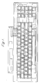
- membrane switch panels for the keyboard as shown in Figure 1 are known to comprise first and second sheets of which at least the upper one is flexible, which are positioned on either side of a third sheet.
- the mutually facing surfaces of the first and second sheets carry positionally-corresponding arrays of contacts and the third sheet which acts as a spacingmember has an array of apertures which positionally correspond with the arrays of contacts on the said first and second sheets.
- Each said aperture defines a switch cell containing a pair of opposed contacts. Pressure on the upper one of said first and second sheets brings the two contacts of the switch cell together within the space defined by the respective aperture in the third sheet so as to make an electrical circuit.
- the upper sheet normally is resilient so as to obviate any necessity for additional biasing means to restore the upper sheet to its normal planar condition after each actuation.
- the bottom sheet may be rigid, in which case the switch panel consisting of the three sheets may be mounted directly into a console, the bottom sheet providing all the necessary support. In the present arrangement, all said sheets are flexible and are adhesively held together.
- the bottom sheet is adhesively mounted on a rigid backing plate.
- the switch actuating members, forming the actuating part of the key modules are mounted by being clipped into C channel strips in which actuating levers, called herein springs, are integrally formed.
- there is a separate spring for each key module mounted on the switch actuator member body, and the latter is secured directly on the upper surface of the membrane switch panel by means of adhesives.
- a blank 2 as shown in Figure 2 is prepared from a suitable material, e.g. plastics, sheet spring steel, sheet beryllium-copper, etc.
- the blank is in the form of an elongate strip and may be of any convenient length depending on the number of key modules to be mounted on the strip.
- a series of regularly spaced notches 3 and along each side there is a row rectangularly shaped apertures 4, the apertures on one side being in registration with the apertures on the other so as to form a longitudinal sequence of equally spaced pairs of apertures alternating with the notches 3.
- U-shaped slots 6 which terminate at each end in larger diameter apertures 7, thus defining a weakened zone 8 at the neck of each U-shaped slot.
- the slots correspond in number with the pairs of rectangular apertures.
- Two rows of holes 9, spaced on each side of the U-shaped slots, enable the strip to be riveted to a base.
- a key module mounting strip is formed by bending up the sides of the strip along fold lines indicated by the dash lines 10 so as to provide a channel of the shape indicated in Figures 3 and 4.
- the tongues defined by the U-shaped slots are deformed about fold lines 11 normal to the axis 12 out of the plane of the floor of the strip and into the channel interior as shown in Figures 3 and 4, so as to provide a row of springs 13.
- Each spring is cantilevered to the floor of the channel and is precisely bent so that its free end is a precise prescribed distance above the floor.
- the notches 3 define a series of coplanar flanges 14 on one side of the channel which may be individually sprung aside to enable a respective key module 15 to be inserted into the channel as shown in Figure 5, or easily removed, the apertures 4 receiving locating lugs or bosses 16 provided on the lateral sides of the key modules 15.
- the channel is mounted, in a parallel array with others to give a keyboard layout required by the particular application, for example as shown in Figure 1, one switch element of which is shown in the enlarged sectional view in Figure 6.
- the membrane switch panel comprises a pair of flexible sheets 18, formed of plastics material, separated by the spacer 19 of plastics material.
- An array of apertures 20 registers with metallic, opposed, contacts 21 deposited with associated interelement printed circuitry (not shown), on the internal facing surfaces of the pair of sheets 18.
- the upper and lower surfaces of the spacer 19 are uniformly covered with an adhesive layer of acrylic material, thus bonding the two sheets 18 and the spacer 19 together.
- the arrangement forms a sealed assembly, imperviously to moisture from, say, accidental spillage of liquids.
- a further layer of adhesive 22 secures the switch membrane assembly to a substructure 26, e.g. a rigid aluminium plate.
- the channel strips are mounted directly onto the switch membrane so that the fold line 11 of each spring 13 coincides with the central axis of the pair of opposed contacts 21 in a respective one of a row of switch elements and so that the pair of holes 7, defining the aforesaid weakened zones 8, correspond with respective internal walls 23 of the spacer.
- the respective key module (not shown in Figure 6) is mounted to the appropriate apertures 4 in the flanges of the channel (on the left, as shown in Figure 6) so that its actuating axis is in line generally with the free end of the spring 13.
- the actuating axis of the key module is therefore displaced from the corresponding switch axis by a distance equal to the length from the bend to the free end of the spring.
- Rivets 24 are used at appropriate intervals to secure the channel strips to the assembly; however, other forms of attachment of the strip may be used, including suitable adhesives.
- the function of the weakened zones 8 of the springs 13 defined by the pairs of holes 7, is to create a line of easy flexure, that is a form of hinge.
- the spring 13 is therefore acting initially as a lever providing a mechanical advantage to actuate the switch of about 4:1.
- the contacts 21 are abutting further displacement of the knee is prevented. Additional pressure on the spring causes overtravel, i.e.
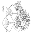
- the body 101 of each of the switch actuating members of the key modules 100 is provided with a foot 102 which extends asymmetrically with respect to the actuating axis of the member so as to abut an adjacent key module when assembled in a keyboard with other similar key modules.
- the foot provides a large planar base area to facilitate attachment of the respective key module to the upper membrane of the membrane switch panel solely by means of an adhesive.
- An elongate recess 103 in the foot houses actuating spring 104.
- Spring 104 has the same function as the springs 13 of the aforesaid first embodiment.
- Each spring is provided with an upstanding dog-leg portion 105 which is lodged in a vertical slot 106 in the side wall of the foot 102 of the respective switch actuating member body and a free arm, comprising first and second portions.
- the first portion, adjacent the dog-leg portion, extends substantially in the plane of the base of the said foot and the second portion extends upwardly from a knee 107 into contact with the lower end of a plunger 108 housed in the said body.
- Plunger 108 has an extension 109 of cruciform section on which the respective key cap 110 mounts in the conventional manner.
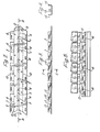
- the membrane switch shown in Figs. 7a to c is represented in an exploded view, as a membrane switch panel 111 forming part-of a keyboard, which part has three key modules and three switch cells.
- the membrane switch panel 111 comprises essentially an upper membrane 112, a lower membrane 113 and a spacing sheet 114 between them.
- both surfaces of the spacing sheet 114 are coated with an acrylic adhesive material.
- the three flexible sheets are then pressed together to form a sealed package which is impervious to moisture.
- the rows of apertures in sheet 114 are linked by slots. These slots may extend to pneumatic terminals (not shown) and be coupled thereby to air inlet filters, etc., or one or more,pneumatic pressure compensators (not shown) by means of which large changes in ambient pressure may be compensated, such as may be experienced, for example, in aviation use.
- a further apertured spacing sheet 118 having an array of apertures 119 in mutual correspondence with the switch cells and the respective key modules.
- Sheet 118 is also coated on both sides with an adhesive material before assembly so that it forms an adherent member for adhesively mounting the key modules on the membrane switch panel 111.
- the apertures 119 are made large enough to accommodate the entire operative length of the spring and the sheet thickness is chosen to provide the specified pre-contact free travel of the spring upon actuation. For the example quoted hereinafter the thickness of the sheet was 5 thousandths of an inch (.125 mm).
- the apertures 119 may be of any convenient shape, e.g.
- a further, usually non-apertured membrane (not shown) coated on both sides with adhesive material may be used to adhesively mount the assembled membrane switch panel 111 on a rigid base plate 120.
- This slot is provided with three internal facing ribs which extend towards the central plane of the slot and are spaced only sufficiently far apart to receive the dog-leg portion 105 of the spring 104 when it is bowed about a vertical axis.
- Fig. 8b which shows a section through the slot 106 along the plane D-D.
- the two ribs 121 on the actuation axis side are cambered at the bottom of the slot so that the dog-leg portion can be easily inserted. As the dog-leg portion is pushed up into the slot, the camber on the said ribs 121 forces it progressively into the bowed shape.
- the dog-leg portion exerts a frictional force on the ribs 121, 122 which maintains it in position in the slot.
- the third rib 122 extends substantially to the base of the slot so as to prevent flexing of the dog-leg portion when the arm of the spring is depressed during normal functioning.
- One of the features of the form of mounting used for the spring in the second embodiment is that any tendency for the spring to come out of the slot in the foot (which is unlikely because of the bowing of the dog leg portion) is overcome when the key is fully actuated because the spring tries to pivot about its knee 107 during the overtravel portion of movement and thereby force the dog-leg portion fully into the slot if it is not so disposed already.
- permanent fixing of the spring onto or in the body of the switch actuating member becomes totally unnecessary, thereby greatly simplifying manufacture and reducing the parts required in this form of the switch actuating member to four, namely the body 101, the spring 104, the plunger 108 and the key cap 110.
- Figures 9a to c illustrate an alternative form of the key module, used in the second embodiment, mainly intended to provide special functions in keyboards used for word processors and the like.
- a keyboard may therefore contain both types of module or adaptations containing some of their features.
- the key module of Figures 9a to c has the same basic parts as the key modules illustrated in Figures 7a to c and operates in exactly the same manner. These basic parts are therefore given the same reference numerals in both sets of figures.
- the key module of Figure 9 is provided with two horizontal elongate recesses 121, 122, and two vertical elongate recesses 123, 124 in the external upper surfaces of the body 101. These recesses are intended to house a light emitting diode 125 and allow a choice of locations, the location being dependent upon the type of key cap which is fitted to the module. In use, the diode is, of course, energised, so as to provide under- illumination of the key cap, whenever the respective key is operated.
- a plurality of slots and passages through the foot of the body which communicate with the aforesaid recesses are provided to enable the terminal wires 126 of the diode to be taken through the foot of the module and through the membrane switch panel and be wired up to switches on the electronic encoding circuit board.
- the said body 101 also has a passage 127 on its upper part through the respective side wall which exposes the lower part (not seen in the drawing) of the plunger 108.
- the latter has a recess in its side, which is aligned with the said aperture 127, which is adapted to receive the cranked end of an optionally fitted double-cranked bar 128, the latter when fitted being pivotally supported and retained within a threequarter- circular-shaped recess 129 provided in a web 130 formed on the side of the body and being similarly supported by identical arrangements on adjacent key modules.
- a similarly recessed web 131 is provided on the same body alongside the first said web on the near side of the aperture 127, as shown, for the purpose of supporting the double-cranked bar from that side.
- the function of the bar is to provide a mechanical linkage which transmits a key displacement from one key module to another key module situated in the same row. Such provision is required, for example, when two spaced apart switch actuating members are employed to support a space bar, or when one lengthened key cap is fitted to two adjacent key modules.
Landscapes
- Push-Button Switches (AREA)
Priority Applications (1)
| Application Number | Priority Date | Filing Date | Title |
|---|---|---|---|
| AT84305716T ATE85155T1 (de) | 1984-03-29 | 1984-08-22 | Mechanische tastatur mit folienschalterfeld. |
Applications Claiming Priority (2)
| Application Number | Priority Date | Filing Date | Title |
|---|---|---|---|
| GB08408181A GB2141874B (en) | 1983-03-31 | 1984-03-29 | Keyboard with membrane switch array |
| GB8408181 | 1984-03-29 |
Publications (3)
| Publication Number | Publication Date |
|---|---|
| EP0157035A2 true EP0157035A2 (fr) | 1985-10-09 |
| EP0157035A3 EP0157035A3 (en) | 1987-03-18 |
| EP0157035B1 EP0157035B1 (fr) | 1993-01-27 |
Family
ID=10558896
Family Applications (1)
| Application Number | Title | Priority Date | Filing Date |
|---|---|---|---|
| EP84305716A Expired - Lifetime EP0157035B1 (fr) | 1984-03-29 | 1984-08-22 | Clavier mécanique, muni d'un champ d'interrupteurs à membrane |
Country Status (3)
| Country | Link |
|---|---|
| EP (1) | EP0157035B1 (fr) |
| AT (1) | ATE85155T1 (fr) |
| DE (1) | DE3486059T2 (fr) |
Cited By (3)
| Publication number | Priority date | Publication date | Assignee | Title |
|---|---|---|---|---|
| US4795897A (en) * | 1986-02-21 | 1989-01-03 | U.S. Philips Corp. | Apparatus for establishing data transfers with a portable electronic card |
| US6591877B1 (en) * | 1999-12-01 | 2003-07-15 | Hoshizaki America, Inc. | Beverage dispenser unit |
| CN114812880A (zh) * | 2021-01-19 | 2022-07-29 | 利永环球科技股份有限公司 | 悬臂力量传感器 |
Families Citing this family (2)
| Publication number | Priority date | Publication date | Assignee | Title |
|---|---|---|---|---|
| DE10113031B4 (de) * | 2001-03-17 | 2004-02-19 | Cimosys Ltd., St. Helier | Elektromotorischer Möbelantrieb zur Verstellung von Teilen eines Möbels relativ zueinender |
| DE102020122745B4 (de) | 2020-08-31 | 2022-03-31 | Cherry Europe Gmbh | Halterungsbauteil für Stabilisatorbügel und Stabilisator-System zur Stabilisierung einer Tastenkappe einer Tastatur, Stabilisator-Set und Tastatur |
Family Cites Families (6)
| Publication number | Priority date | Publication date | Assignee | Title |
|---|---|---|---|---|
| US3909564A (en) * | 1974-08-08 | 1975-09-30 | Amp Inc | Keyboard assembly with foldable printed circuit matrix switch array, and key actuator locking slide plate |
| DE2440265A1 (de) * | 1974-08-22 | 1976-03-11 | Kienzle Apparate Gmbh | Tastatur |
| SE7612000L (sv) * | 1975-10-30 | 1977-05-01 | Chomerics Inc | Tangentbordsklaviatur |
| US4249044A (en) * | 1979-04-23 | 1981-02-03 | Oak Industries, Inc. | Membrane switch with means for preventing contamination of the interior thereof |
| US4316066A (en) * | 1979-09-10 | 1982-02-16 | International Telephone And Telegraph Corporation | Key switch with snap-action contact and resilient actuator |
| US4467150A (en) * | 1982-02-24 | 1984-08-21 | Digital Equipment Corporation | Electronic keyboard |
-
1984
- 1984-08-22 DE DE8484305716T patent/DE3486059T2/de not_active Expired - Fee Related
- 1984-08-22 AT AT84305716T patent/ATE85155T1/de not_active IP Right Cessation
- 1984-08-22 EP EP84305716A patent/EP0157035B1/fr not_active Expired - Lifetime
Cited By (3)
| Publication number | Priority date | Publication date | Assignee | Title |
|---|---|---|---|---|
| US4795897A (en) * | 1986-02-21 | 1989-01-03 | U.S. Philips Corp. | Apparatus for establishing data transfers with a portable electronic card |
| US6591877B1 (en) * | 1999-12-01 | 2003-07-15 | Hoshizaki America, Inc. | Beverage dispenser unit |
| CN114812880A (zh) * | 2021-01-19 | 2022-07-29 | 利永环球科技股份有限公司 | 悬臂力量传感器 |
Also Published As
| Publication number | Publication date |
|---|---|
| ATE85155T1 (de) | 1993-02-15 |
| DE3486059T2 (de) | 1993-08-26 |
| EP0157035B1 (fr) | 1993-01-27 |
| DE3486059D1 (de) | 1993-03-11 |
| EP0157035A3 (en) | 1987-03-18 |
Similar Documents
| Publication | Publication Date | Title |
|---|---|---|
| US4582967A (en) | Key switch assembly | |
| EP0087369B2 (fr) | Clavier électronique amélioré | |
| US3996428A (en) | Pushbutton keyboard assembly with over center diaphragm contact | |
| US4360722A (en) | Designation cap actuator assembly | |
| US3971902A (en) | Keyboard switch assembly having one piece plural pushbutton actuator and resilient mounting structure for plural cantilever beam contacts | |
| US20030226745A1 (en) | Tactile switch unit | |
| JPS59186214A (ja) | 押釦スイツチ | |
| US3940578A (en) | Keyboard structure having panel mounted key actuators with electrical component operating element | |
| US3777090A (en) | Linear cam actuated diaphragm switch with lost motion actuator | |
| US5969644A (en) | Keyboard | |
| US6268578B1 (en) | Key switch used in a keyboard | |
| EP0500330A2 (fr) | Interrupteur pour clavier plat | |
| EP0157035A2 (fr) | Clavier mécanique, muni d'un champ d'interrupteurs à membrane | |
| CA1154000A (fr) | Clavier et mode de realisation | |
| GB2141874A (en) | Keyboard with membrane switch array | |
| US4892024A (en) | Structure of keyboard used in electronic keyboard instrument | |
| US4099037A (en) | Key board switch assembly having canti-levered leaf spring contact assembly on common conductive frame | |
| JP2539161Y2 (ja) | 電子楽器の鍵ガイド装置 | |
| US4709128A (en) | Easily positionable keyboard | |
| EP0155390B1 (fr) | Méthode de fabrication d un interrupteur à action brusque | |
| JPS6028025Y2 (ja) | 電子楽器の鍵盤装置 | |
| US4320272A (en) | Connector for attaching an electrical component to a flat sheet | |
| JPH0122188Y2 (fr) | ||
| JPH0227468Y2 (fr) | ||
| JPS6028023Y2 (ja) | 電子楽器の鍵盤装置 |
Legal Events
| Date | Code | Title | Description |
|---|---|---|---|
| PUAI | Public reference made under article 153(3) epc to a published international application that has entered the european phase |
Free format text: ORIGINAL CODE: 0009012 |
|
| AK | Designated contracting states |
Designated state(s): AT BE CH DE FR IT LI LU NL SE Kind code of ref document: A2 Designated state(s): AT BE CH DE FR IT LI LU NL SE |
|
| PUAL | Search report despatched |
Free format text: ORIGINAL CODE: 0009013 |
|
| AK | Designated contracting states |
Kind code of ref document: A3 Designated state(s): AT BE CH DE FR IT LI LU NL SE |
|
| 17P | Request for examination filed |
Effective date: 19870917 |
|
| 17Q | First examination report despatched |
Effective date: 19900222 |
|
| RTI1 | Title (correction) | ||
| GRAA | (expected) grant |
Free format text: ORIGINAL CODE: 0009210 |
|
| AK | Designated contracting states |
Kind code of ref document: B1 Designated state(s): AT BE CH DE FR IT LI LU NL SE |
|
| PG25 | Lapsed in a contracting state [announced via postgrant information from national office to epo] |
Ref country code: SE Effective date: 19930127 Ref country code: NL Effective date: 19930127 Ref country code: LI Effective date: 19930127 Ref country code: CH Effective date: 19930127 Ref country code: BE Effective date: 19930127 Ref country code: AT Effective date: 19930127 |
|
| REF | Corresponds to: |
Ref document number: 85155 Country of ref document: AT Date of ref document: 19930215 Kind code of ref document: T |
|
| REF | Corresponds to: |
Ref document number: 3486059 Country of ref document: DE Date of ref document: 19930311 |
|
| ITF | It: translation for a ep patent filed | ||
| REG | Reference to a national code |
Ref country code: CH Ref legal event code: PL |
|
| ET | Fr: translation filed | ||
| NLV1 | Nl: lapsed or annulled due to failure to fulfill the requirements of art. 29p and 29m of the patents act | ||
| PGFP | Annual fee paid to national office [announced via postgrant information from national office to epo] |
Ref country code: FR Payment date: 19930805 Year of fee payment: 10 |
|
| PGFP | Annual fee paid to national office [announced via postgrant information from national office to epo] |
Ref country code: DE Payment date: 19930823 Year of fee payment: 10 |
|
| PG25 | Lapsed in a contracting state [announced via postgrant information from national office to epo] |
Ref country code: LU Free format text: LAPSE BECAUSE OF NON-PAYMENT OF DUE FEES Effective date: 19930831 |
|
| PLBE | No opposition filed within time limit |
Free format text: ORIGINAL CODE: 0009261 |
|
| STAA | Information on the status of an ep patent application or granted ep patent |
Free format text: STATUS: NO OPPOSITION FILED WITHIN TIME LIMIT |
|
| 26N | No opposition filed | ||
| PG25 | Lapsed in a contracting state [announced via postgrant information from national office to epo] |
Ref country code: FR Effective date: 19950428 |
|
| PG25 | Lapsed in a contracting state [announced via postgrant information from national office to epo] |
Ref country code: DE Effective date: 19950503 |
|
| REG | Reference to a national code |
Ref country code: FR Ref legal event code: ST |
|
| REG | Reference to a national code |
Ref country code: FR Ref legal event code: RN |
|
| REG | Reference to a national code |
Ref country code: FR Ref legal event code: D5 |