EP0157128A1 - Appareil électrique pour le traitement d'aliments - Google Patents
Appareil électrique pour le traitement d'aliments Download PDFInfo
- Publication number
- EP0157128A1 EP0157128A1 EP85101416A EP85101416A EP0157128A1 EP 0157128 A1 EP0157128 A1 EP 0157128A1 EP 85101416 A EP85101416 A EP 85101416A EP 85101416 A EP85101416 A EP 85101416A EP 0157128 A1 EP0157128 A1 EP 0157128A1
- Authority
- EP
- European Patent Office
- Prior art keywords
- wheel
- housing
- fan wheel
- adapter
- electrically operated
- Prior art date
- Legal status (The legal status is an assumption and is not a legal conclusion. Google has not performed a legal analysis and makes no representation as to the accuracy of the status listed.)
- Withdrawn
Links
- 238000012545 processing Methods 0.000 title claims abstract description 18
- 238000001816 cooling Methods 0.000 claims abstract description 10
- 235000013305 food Nutrition 0.000 claims description 18
- 238000002360 preparation method Methods 0.000 abstract description 2
- 238000010168 coupling process Methods 0.000 description 53
- 238000005859 coupling reaction Methods 0.000 description 53
- 230000008878 coupling Effects 0.000 description 43
- 230000013011 mating Effects 0.000 description 17
- 239000006071 cream Substances 0.000 description 13
- 238000013461 design Methods 0.000 description 12
- 238000004898 kneading Methods 0.000 description 10
- 239000000945 filler Substances 0.000 description 6
- 230000002093 peripheral effect Effects 0.000 description 6
- 238000004519 manufacturing process Methods 0.000 description 4
- 239000000463 material Substances 0.000 description 4
- 230000004048 modification Effects 0.000 description 4
- 238000012986 modification Methods 0.000 description 4
- 244000188595 Brassica sinapistrum Species 0.000 description 2
- 235000004977 Brassica sinapistrum Nutrition 0.000 description 2
- 235000014103 egg white Nutrition 0.000 description 2
- 210000000969 egg white Anatomy 0.000 description 2
- 235000012020 french fries Nutrition 0.000 description 2
- 239000007788 liquid Substances 0.000 description 2
- 239000008268 mayonnaise Substances 0.000 description 2
- 235000010746 mayonnaise Nutrition 0.000 description 2
- 235000021116 parmesan Nutrition 0.000 description 2
- 238000012549 training Methods 0.000 description 2
- 239000008256 whipped cream Substances 0.000 description 2
- 208000027418 Wounds and injury Diseases 0.000 description 1
- 238000013459 approach Methods 0.000 description 1
- 230000015572 biosynthetic process Effects 0.000 description 1
- 230000006378 damage Effects 0.000 description 1
- 238000006073 displacement reaction Methods 0.000 description 1
- 230000000694 effects Effects 0.000 description 1
- 208000014674 injury Diseases 0.000 description 1
- 238000009434 installation Methods 0.000 description 1
- 230000003993 interaction Effects 0.000 description 1
- 239000000203 mixture Substances 0.000 description 1
- 238000005192 partition Methods 0.000 description 1
- 230000000149 penetrating effect Effects 0.000 description 1
- 230000009467 reduction Effects 0.000 description 1
- 210000004894 snout Anatomy 0.000 description 1
- 238000003756 stirring Methods 0.000 description 1
- 230000008719 thickening Effects 0.000 description 1
- 238000012546 transfer Methods 0.000 description 1
Images


Classifications
-
- A—HUMAN NECESSITIES
- A47—FURNITURE; DOMESTIC ARTICLES OR APPLIANCES; COFFEE MILLS; SPICE MILLS; SUCTION CLEANERS IN GENERAL
- A47J—KITCHEN EQUIPMENT; COFFEE MILLS; SPICE MILLS; APPARATUS FOR MAKING BEVERAGES
- A47J43/00—Implements for preparing or holding food, not provided for in other groups of this subclass
- A47J43/04—Machines for domestic use not covered elsewhere, e.g. for grinding, mixing, stirring, kneading, emulsifying, whipping or beating foodstuffs, e.g. power-driven
- A47J43/07—Parts or details, e.g. mixing tools, whipping tools
- A47J43/075—Safety devices
- A47J43/0761—Safety devices for machines with tools driven from the lower side
- A47J43/0772—Safety devices for machines with tools driven from the lower side activated by the proper positioning of the cover
-
- A—HUMAN NECESSITIES
- A47—FURNITURE; DOMESTIC ARTICLES OR APPLIANCES; COFFEE MILLS; SPICE MILLS; SUCTION CLEANERS IN GENERAL
- A47J—KITCHEN EQUIPMENT; COFFEE MILLS; SPICE MILLS; APPARATUS FOR MAKING BEVERAGES
- A47J43/00—Implements for preparing or holding food, not provided for in other groups of this subclass
- A47J43/04—Machines for domestic use not covered elsewhere, e.g. for grinding, mixing, stirring, kneading, emulsifying, whipping or beating foodstuffs, e.g. power-driven
- A47J43/046—Machines for domestic use not covered elsewhere, e.g. for grinding, mixing, stirring, kneading, emulsifying, whipping or beating foodstuffs, e.g. power-driven with tools driven from the bottom side
-
- A—HUMAN NECESSITIES
- A47—FURNITURE; DOMESTIC ARTICLES OR APPLIANCES; COFFEE MILLS; SPICE MILLS; SUCTION CLEANERS IN GENERAL
- A47J—KITCHEN EQUIPMENT; COFFEE MILLS; SPICE MILLS; APPARATUS FOR MAKING BEVERAGES
- A47J43/00—Implements for preparing or holding food, not provided for in other groups of this subclass
- A47J43/04—Machines for domestic use not covered elsewhere, e.g. for grinding, mixing, stirring, kneading, emulsifying, whipping or beating foodstuffs, e.g. power-driven
- A47J43/07—Parts or details, e.g. mixing tools, whipping tools
- A47J43/08—Driving mechanisms
- A47J43/085—Driving mechanisms for machines with tools driven from the lower side
Definitions
- the invention relates to an electrically operated device for processing and preparing food of all kinds, with a housing for accommodating the electric motor and associated switching and control devices, with a receptacle arranged next to the housing, in the interior of which a work tool is arranged, whose working shaft carries a wheel at its free end, which in turn receives a belt, preferably a toothed belt, which is guided over another wheel, which is fastened to the free end of the motor shaft and with a fan wheel for generating cooling air for the electric motor.
- a special, ie additional fan wheel is provided, which is attached to the free end of the motor shaft of the electric motor.
- the one wheel for the belt and the fan wheel are arranged one behind the other on the motor shaft.
- This known embodiment requires the use of a special, that is to say an additional, fan wheel, which, moreover, is to be attached to the motor shaft in a rotationally fixed manner with the fastening means assigned to it. This increases the workload in the manufacture and assembly.
- the selected arrangement of the wheel and fan wheel on the motor shaft results in a comparatively large space requirement inside the device housing.
- the invention has for its object to further improve electrically operated devices for processing and preparing foods of the type described in more detail at the outset in such a way that the disadvantages mentioned of known embodiments of such devices are eliminated.
- a solution is to be found for the design and design of the wheel and impeller, which reduces the manufacturing and assembly work and in which the space required for these parts inside the device housing is reduced to a minimum.
- This goal is achieved in that one of the two wheels for the belt is designed directly as a fan wheel.
- This training according to the invention has significant advantages over the known. First of all, there is no need to manufacture and attach an additional fan wheel. This also eliminates the need for special fastening elements with which the fan wheel can be attached to the motor shaft in a rotationally fixed manner. Furthermore, there is a much smaller installation dimension, because the previously common arrangement of the wheel for the toothed belt and the separate fan wheel has been dispensed with. Instead, only as much space is required inside the device housing as is necessary to accommodate a belt wheel anyway.
- the additional fan wheel is arranged directly on the motor shaft, it rotates with a large number of revolutions, which is associated with a high level of noise.
- a further object of the present invention is therefore to remedy the situation, that is to choose such an arrangement and shape of the fan wheel that the noises generated during the rotation are significantly reduced in comparison with the known.
- the wheel arranged on the working shaft of the device as a fan wheel. It is recommended that the fan wheel, which is arranged on the working shaft, be kept many times larger in diameter than the second wheel of the belt drive arranged on the motor shaft.
- the fan wheel - which is also identical to the one wheel of the belt drive - no longer sits on the fast rotating motor shaft of the electric motor but on the working shaft rotating at a lower number of revolutions. It must be taken into account that there is a reduction due to the shaft of the belt drive having different diameters, the wheel with the smaller diameter being arranged on the motor shaft and the fan wheel with its substantially larger diameter being arranged on the drive shaft.
- areas of the inner walls of the housing foot can be formed directly as air guide channels. This can preferably be done by profiling the inner wall in regions or also by means of ribs formed there.
- the fan wheel have a plurality of blades, one end of which is fastened to the hub or a part assigned to it and the other end of which is fastened to the inside of the outer ring which carries the teeth for a toothed belt.
- the blades of the fan wheel can have a training and design known per se. In this case, if the space inside the housing should allow, there is also the possibility of arranging such generally known blades which project beyond the hub or the outer ring with regard to their width dimensions.
- a housing 3 0 are housed in which the electric motor and the control and switching means of the device.
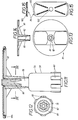
- the housing 3o has a housing foot 31, wherein the housing 3o and housing foot 31 - as can be seen in FIG. 1 - are essentially L-shaped.
- a receptacle (pot), generally designated 32, is placed on the surface of the housing foot 31 lying next to the housing 30. The receptacle 32 is to be secured on the device foot 31 in a camouflaged manner against lifting off, such as by a bayonet-type holder.
- the receptacle 32 has a molded handle 33 and a removable cover 34, which in turn is equipped with a filler neck 35, through which the food to be shredded is fed in a known manner.
- the lid 34 is also secured to the receptacle 32 by, for example, gripping projections.
- An electric motor 125 known per se is accommodated in the housing, which is not visible in FIG. 1 of the drawing, but is shown in dash-dot lines in FIG. 17.
- the electric motor 125 and a motor cover 36 are received by a carrier plate 96 which extends essentially over the entire length of the housing foot 31.
- the support plate 96 cooperates with supports 98 which are molded on the inside of the walls of the housing foot 31 and ensure the position of the support plate 96.
- the supports 98 act on the carrier plate 96 from different sides.
- the electric motor 125 has a motor shaft 37, the free end of which projects into the cavity of the housing foot 31 and carries a wheel 38 there, which cooperates with a belt, preferably with a toothed belt 39.
- This toothed belt 39 - as can be seen in FIG. 1 - is guided around via a drive wheel 4o which is substantially larger in diameter.
- This drive wheel 4o is designed according to the invention as a fan wheel and has on its peripheral surface lying a plurality of teeth 41 which cooperate with the counter teeth of the toothed belt 39, which are not described in any more detail, in a manner known per se.
- the drive wheel 4o designed as a fan wheel is arranged on the end of a working or tool shaft 42 which projects into the cavity of the housing foot 31.
- the impeller is kept 4 0 on the end of the drive shaft 42 by a nut 99 with interposition of a washer loo.
- other known types of fastening can also be used to hold the fan wheel 4o on the tool or drive shaft 42.
- fastening options for the free end of the tool or drive shaft 42 can be provided in the area of the hub 44 of the fan wheel 40.
- the form-fitting arrangement of a non-circular nut in the hub 44 of the fan wheel 4o is possible.
- a plurality of blades 43 are assigned to the fan wheel 43. There are numerous possibilities with regard to the design and design of these blades 43. Two of these possible embodiments are shown in FIGS. 3 and 4 of the drawing.
- the blades 43 can not only be connected to the hub 44 in a manner known per se but also in a manner known per se.
- a one-piece design is also conceivable. As far as the space in the cavity of the housing foot permits and as long as there is no excessive noise during operation, it is also possible to let the blades protrude beyond the edge of the fan wheel 4o.
- the housing foot 31 is configured in two parts, the two parts being able to be held together by known - and therefore omitted - means.
- the lower, unspecified part of the housing foot 31 rests on a surface, for example on a table top.
- the upper part 45 has a smooth opening 47 for penetrating the working or tool shaft 42. This opening lies in the area of the ceiling 46 of the upper part 45, the ceiling 45 passing over a shoulder 48 into the outer surface.
- the receptacle 32 (pot) has on its underside projections 49 which are directly molded onto the bottom 50 of the receptacle 32.
- the projections 49 - which are at a distance from one another - cooperate with the outer surface of the shoulder 48, so that a transverse displacement of the receptacle 32 on the stand 31 is not possible.
- a sleeve-like projection 51 is molded onto the bottom 50 of the receptacle 32. This protrudes - as shown in FIGS. 1 and 4 of the drawing - relatively far into the interior of the receptacle 32.
- the upper end of the working or tool shaft 42 protrudes into the sleeve-like projection 51.
- the working or tool shaft 42 is offset several times in terms of diameter and has, for example in the area of the sleeve-like projection 51, two fastening regions 53 which are arranged at a distance from one another and act as knurls their outer surface are formed.
- These fastening areas 53 serve for the firm connection to an insulating sleeve, generally designated 52, which is made in one piece from a plastic and is closed at the top.
- the opposite other end of the insulating sleeve 52 is designed as a disk-like foot 54 which - as best shown in FIG. 4 - is arranged in the space 127 between the cover 46 and the bottom 50 of the receptacle 32.
- This disk-like foot 54 ensures that liquids that should have come from the receptacle 32 into the intermediate space 127 when the electrically operated device is in use through the sleeve-like projection 51 are thrown out of this again and thereby pass through the gap 126 or through the free spaces between the projections 49 can get outside.
- Coupling projections 55 are provided on the outside of the insulating sleeve 52, which cooperate with mating couplings 58 of an adapter, generally designated 56. Seen in plan view, the coupling projections 55 of the insulating sleeve 52 form an approximately wave-shaped or gear-shaped surface that closes in a circle. The mating couplings 58 of the adapter 56 engage between the coupling projections 55 in the troughs or the tooth gaps, the force application surfaces being essentially perpendicular to one another. In this way, the adapter 56 is coupled to be carried along.
- the counter-couplings 58 are designed so that a form-fitting interaction with the couplings 55 takes place.
- the adapter has an inner section 57 which is open at the bottom.
- the lower region of the inner section 57 engages in the space between the inner wall of the sleeve-like projection 51 and the outer wall of the insulating sleeve 52, the coupling projections 55 of the insulating sleeve 52 with the mating couplings 58 on the inner wall of the inner section being shown in FIG. 4 57 are engaged with each other.
- the adapter 57 is coupled to the insulating sleeve 52 so that it can be carried along.
- the adapter 56 also has an outer section 59 which is closed at the top but is open at the bottom.
- the adapter 56 mating couplings 6 0 cooperating with couplings 61 of a tool.
- the counter-couplings 6o are mutually identical and are evenly distributed over the lower region of the peripheral surface of the outer section 59. It also applies here that, seen in plan view, the lower region of the outer section 59 has undulating or gear-shaped surfaces which close to form a circle.
- the couplings 61 fit into the troughs or tooth gaps between the mating couplings 6o.
- the couplings and mating couplings of both adapter 56 and the insulating sleeve 52 it applies that in the illustrated embodiments these run in the direction of the longitudinal axis of the adapter 56 or the insulating sleeve 52.
- the couplings and counter-couplings can also enclose an angle with this longitudinal axis. The same applies to the couplings of the tools which interact with the adapter 56 and which must have an adapted inclination in this variant.
- the counter-couplings 6o of the outer section 59 of the adapter 56 work together with couplings 61 of tools (work tools).
- one and the same adapter 56 is assigned a plurality of differently designed tools which, depending on the work to be carried out, are optionally used by the user and are each detachably connected to the adapter 56.
- FIG. 7 and 8 show a knife generally designated 65.
- This has two sickle-shaped knife blades 66, which are sharpened in a known manner and which - see FIG. 7 of the drawing - are arranged in different planes.
- One blade wing 66 faces the bottom 5o of the receptacle 32, while the diametrically opposite other blade wing 66 lies at a greater distance from this base 5o.
- the two knife blades 66 are firmly connected to the hub 67 of the knife 65 by rivets 68.
- the hub 67 also has the couplings 61 already mentioned, which cooperate with the counter-couplings 60 of the outer section 59 of the adapter 56.
- a support edge 69 is provided which interacts with a projection of the adapter 56, which is not described in more detail. From the position shown in FIG. 7 - the working position - it follows that the support edge 69 of the knife 65 is supported at such a height on the adapter 56 that the lower of the two knife wings 66 is at a short distance from the bottom 50 of the receptacle 32 is arranged.
- a further tool optionally to be coupled with the adapter 56. It is a kneading tool generally designated 62.
- This kneading tool 62 is made in one piece from a material, for example from a plastic, and has two mutually identically shaped wings 64, each of which has curved boundary surfaces which end in a tip.
- the vanes 64 are identical to one another, but are molded onto the hub 63 of the kneading tool 62 at different heights.
- the hub 63 in turn has couplings 61 which cooperate with the mating couplings 60 of the adapter 56.
- the couplings 61 of the kneading tool 62 can be configured in the same way as those of the knife 65.
- the kneading tool 62 also has a support edge 69 which, in the manner already described, interacts with a shoulder (not described in more detail) lying on the outer surface of the adapter 56.
- the cream slice 7o has on its side facing the bottom of the receptacle 32 a plurality of ribs 72 arranged in a star shape, which, however, differ are dimensioned long, in each case alternating between a short and a long rib 72, the longer rib 72 each opening into the hub of the cream disk 7o, which is designed as a driving hub 71.
- the longer ribs 72 include air guide channels 73, the lower wall of which, when used as intended, is formed by the inner surface of the bottom 46 of the receptacle 32.
- the ribs 72 lie with their outer surfaces on the bottom 5o of the up. receptacle 32.
- Air inlet openings 74 are assigned to the air guiding channels 73 in the area of the driving hub 71, while air outlet openings 10 are formed by the free space between adjacent ribs 72 on the peripheral region of the cream disk 7o.
- the air inlet openings 74 are formed by wall parts 75 that bulge upward in a pocket-like manner, with two longer adjacent ribs 72 being associated with a wall part 75 forming an air inlet opening 74.
- the driving hub 71 in turn has couplings 61 which correspond to those of the knife 65 or the kneading tool 62. These couplings 61 in turn interact with the mating couplings 6o of the adapter 56, with the only difference that the support edge 69 in the working position according to FIG. 9 is now arranged in the region of the mating couplings 6o of the adapter 56 in the region of the mating couplings. This is done to ensure that the outer surfaces of the ribs 72 - as desired - rest on the bottom 50 of the receptacle 32.
- the support edge 69 can be used as a driver, namely when the adapter 56 together with the cream disk 7o is to be pulled out of the insulating container 52 from the receptacle 32.
- the 7o cream slice is used not only to prepare whipped cream, but also to prepare egg whites, mayonnaise and the like.When using such a 7o cream slice, not only is a stirring effect achieved, but the creamy consistency of the material to be mixed is achieved by distributing the finest air bubbles in the mix to achieve.
- the material to be stirred is arranged in a bead-like manner as a result of the centrifugal force in the corner-ring region of the bottom 50 of the receptacle 32 and interspersed with the finest air bubbles. Due to this intensive mode of operation of the cream slice 7o, the time required, even for the production of large quantities of whipped cream, egg whites, mayonnaise or the like. low.
- the adapter 56 shown it is not only provided to selectively assign one of the differently designed tools in its lower region, that is to say the bottom 50 of the receptacle 32, but it will also be Possibility given in the upper area, that is to say the cover 34, either to couple work tools directly to the adapter 56 or to detachably fasten a tool carrier 81 there, which in turn has work tools such as a squeegee disk, French fries disk, friction disk, Parmesan disk or the like. wearing.
- work tools such as a squeegee disk, French fries disk, friction disk, Parmesan disk or the like. wearing.
- the adapter 56 has an extension 76 which is reduced in diameter compared to the lower region of the adapter 56.
- the extension 76 extends approximately to the cover 34.
- a bearing 77 is provided in a thickening of the cover 34, which serves to accommodate a bearing pin 78, the end of which protrudes from the bearing 77 into a bore 79 in the front free end the extension 76 of the adapter 56 engages.
- Such a bearing allows the cover 34 to be easily removed from the receptacle 32. This is because the bearing pin 58 can be easily pulled out of the bore 79 of the extension 76 of the adapter 56. Conversely, when the cover 34 is placed, its bearing pin engages again in this bore 79.
- mating couplings 8o On the outer surface of the extension 76 of the adapter 56 - in the upper area facing the cover 34 - there are mating couplings 8o, which correspond in structure and also in their operation to the mating couplings 6o that are present in the lower area of the adapter 56 . It should only be noted that there are differences insofar as the lengths of the mating couplings 6o and 8o can differ from one another. These mating couplings 8o can - which is not shown in the drawings - interact directly with a work tool known per se which comminutes the material fed through the filler neck 35 of the cover 34.
- the extension 76 is associated with a tool carrier, generally designated 81, which has the shape of a carrier disk having.
- the tool carrier 81 has a hub 82, through which a bore passes, on the inner walls of which couplings 83 are arranged, which interact with the counter-couplings 8o of the extension 76 of the adapter 56 in the manner already described.
- the cross-sectional view according to FIG. 12 shows that in this case too, the couplings 83 and counter-couplings 8 0 have a wave-like shape that complements a circle.
- the extension 56 is provided with mating couplings 8o up to the free end.
- the counter-couplings 8o can also be ended beforehand and the front free end of the extension 76 can be made cylindrical.
- the free end of the extension 76 thus ends in an externally smooth-walled cylinder with a constant diameter that is smaller than the outer diameter of the extension 76 and approximately corresponds to the core diameter of the shaft of the extension 76 that has the coupling ribs 8o.
- the effective support height of this paragraph can be adjusted to the height of the hub of the tool to be picked up in order to always ensure the same distance from the lower edge of the filler shaft for tools of different heights.
- the free end of the hub 82 of the tool carrier 81 is supported on the shoulder of the adapter 56, which is not designated in any more detail and is formed by different diameters.
- a modification can also be made here by making the hub 82 shorter so that it does not interact with the mentioned paragraph of the adapter 56. In this case, one can ensure that the tool is fixed in position on the extension 76 of the adapter 56 by forming a shoulder between couplings and counter-couplings.
- FIGS. 15 and 16 of the drawing A tool which can be detachably connected to the tool carrier 81 is shown in FIGS. 15 and 16 of the drawing, namely this tool is a rasp disk 84.
- the rasp disk 84 is a body which is approximately rectangular in plan view , which has an extension 85 on each of its two narrow sides, which is bent out of the base plane of the rasp disk 84 in order to engage under the edge lo4 of the tool carrier 81, as can be seen in FIG. 11.
- the rasp disk 84 also has a centrally arranged opening 1 0 2, which is surrounded by a circumferential collar 1 0 3 which projects downwards, that is to say in the direction of the adapter 56. Through the opening 102 of the rasp disk 84 grips the front end of the extension 76.
- the rapeseed disk 84 or another - basically known - tool can act on the food in a known manner, which can be fed through the filler neck 35 of the cover 34.
- the tool carrier 81 can then be assigned a different tool than the rapeseed disc 84 shown.
- the device for processing and preparing food designed according to the invention also includes a safety device, the design and shape of which can be seen from FIGS. 17 and 18 of the drawing.
- a safety device is intended to prevent the device from being started up when the cover 34 is removed, which could result in injury to the user because the rotating work tools would be freely accessible.
- the lid 34 of the receptacle 32 is provided with an extension 86, the front free area of which is designed as toothing 87.
- This toothing 87 interacts with a ratchet wheel or pinion 88 which is rotatably mounted on the housing 30.
- the ratchet wheel or pinion is also assigned a stop 89 which, in the position of the ratchet wheel 88 according to FIG. 18, bears against one end of a recess 95.
- Part of the ratchet wheel and pinion 88 is also a tubular extension 9 0, projecting with respect to a central disc-shaped hub 114 of the ratchet wheel 88 in both directions.
- In the lower bore of the sleeve-shaped projection 90 engages lo5 einVorsprung of the housing 3 0th
- the switching wheel 88 is rotatably mounted on this projection lo5.
- To the housing 3o also includes a cover 1 0 6, which forms the upper end of the housing 3o and has a breakthrough 1 0 7 lying in the middle, engage in the above edge regions 1 0 8 of a rotary knob 91.
- the rotary knob 91 Lying on the inner wall of its ceiling, the rotary knob 91 has a hollow pin 1 0 9, which is used to accommodate a bearing or actuating pin 10, which in turn is assigned to a switch 92.
- This switch 92 can have a structure known per se, so that in FIGS Drawing only the housing of the switch 92 is illustrated.
- the switch 92 can also be releasably connected to parts of the housing 3o via latching connections 130.
- the upper part of the tubular extension 9o of the ratchet wheel 88 has two slots 111 which are arranged such that the edge region 1o8 can enter them when the rotary knob 91 is actuated and thus prevent the ratchet wheel 88 from rotating.
- the boundary walls of the slots 111 are curved, the center of curvature coinciding with the center of the rotary knob 91. It remains to be added that the extension 86 of the cover 34 extends through a receiving slot 94 of the housing in such a way that the toothing 87 comes to lie within the housing 30.
- the extension 86 of the cover 34 When the extension 86 of the cover 34 is rotated, its toothing 87 comes into operative connection with the teeth of the ratchet wheel or pinion 88, which is rotatably mounted on the hollow projection lo5 of the housing 3o.
- the teeth of the ratchet wheel 88 are arranged on the peripheral surface of the disk-shaped hub 114. However, as shown in FIG. 18, the teeth only grasp a partial area of the circumferential surface of the hub 114. Another part of the circumferential surface is provided with the recess 95, in which the stop pin 89 engages to limit the rotation of the ratchet wheel 88.
- the position of the recess 95 determines the angle of rotation of the ratchet wheel 88.
- the switching wheel 88 has been rotated via the toothing 87 of the extension 86 of the cover 34 into the ready-to-switch position shown in FIG. 18, In this position, a recess 131 arranged in the ring shoulder 1 0 8 of the rotary knob 91 overlaps the tubular extension of the ratchet wheel 88.
- the teeth 111 of the extension 86 on the cover 34 are the slots 111 of the ratchet wheel 88 in such a position that the ring shoulder lo8 when the rotary knob 91 is turned can pass through the slots 111 in order to be able to move the switch 92 into one of its switch positions when the rotary knob 91 is actuated.
- edge region 1 0 8 of the rotary knob 91 can only engage in the slot 111 of the tubular extension 90 when the switch-ready position shown in FIG. 18 has been assumed.
- a cable holder 93 is arranged on the outer surface of the housing 30.
- a motor cover shown in FIGS. 19 and 20, generally designated 36.
- this has the task of reducing the formation of noise during operation of the device and, on the other hand, in cooperation with the outer walls of the electric motor 125, it serves to guide the cooling air which is generated by the fan wheel 4o.
- the motor cover 36 is made in the selected embodiment as a one-piece body made of plastic.
- the motor cover 36 is provided on its side facing the rotary knob 91 with an oval opening 115, which is surrounded by a peripheral, raised edge 116.
- This edge 116 is used to accommodate a strip-shaped seal 117, which is attached to the edge 116 by means of a slot, not specified.
- the seal 117 interacts with adjacent regions of an intermediate wall 118 of the housing 3o.
- the engine cover 36 also has a chamber-term receiving space 119 lying near the edge 116, in which a buffer piece 12o for holding the engine is arranged, as can be seen in FIG. 17.
- the same FIG. 17 also shows that openings 121 are present in the intermediate wall 118, through which the cooling air can flow outside in the direction of the arrows 129 drawn therein. This is done after multiple deflection through a gap 122 between the housing and the cover 3o 1 0 6.
- On the outer side lying has the peripheral surface of the motor cover 36 stiffening ribs 123, which extend in the axial longitudinal direction of the Motorabdeckung'36.
- the motor cover 36 is also open in its lower end facing the housing foot 31.
- the air set in motion by the fan wheel 40 can thus also get into the space between the outer walls of the electric motor 125 and the inner wall of the motor cover 36 and from there finally reach the outside in the direction of the arrows 129 shown in FIG. 17 through the gap 122.
- the motor cover 36 is detachably connected to the carrier plate 96 1.
- Push-in connections, snap-in connections or snap-in connections can be used as connection means, that is to say connections which allow both easy attachment and, if required, simple removal of the motor cover 36 from the carrier plate 96.
- These connections are generally designated 124 in FIG. 19.
- a double bearing is provided for the adapter 56, because the adapter 56 is not only seated on the insulating sleeve 52 in its lower region, but it is using the bearing pin 78 on the cover 34 of the receptacle 32 additionally stored. In special cases, this second bearing point in the area of the cover 34 can be dispensed with.
- the extension 76 is only guided up to the vicinity of the inner wall of the cover 34 without being stored there. In such an embodiment, the arrangement of a bore in the region of the free end of the extension 76 of the adapter can be dispensed with.
- the design and also the number of work tools assigned to the adapter 56 can be varied in many ways, i.e. the knife, the kneading tool, the cream disk can receive a different embodiment than the one shown.
- other tools known per se can also be provided with couplings so that they can be releasably connected to the adapter 56 in the manner according to the invention. It is also possible to vary the shape and design of both the couplings and the counter-couplings of the tool and adapter. This applies in particular to the cross-sectional design of these parts.
- the rasp disc 84 other than the illustrated rasp disc 84 can also be assigned to the tool carrier 81.
- the use of grater discs, french fries discs, friction discs or Parmesan discs is possible. In principle, it is also contemplated to releasably connect these work tools directly to the extension 76 of the adapter, in which case the use of a tool carrier 81 could be dispensed with.
- the housing foot 31 in the region of the impeller 4 may be 0 provided lying suction ports for fresh air. It is advisable not to put the floor or the like directly on a table surface. to rest but to provide feet on the floor that guarantee that the floor is at a distance corresponding to the height of these feet from the table top. This allows fresh air to be drawn in unhindered. Furthermore, it is expedient to provide air guide channels in the interior of the housing foot, which convey the fresh air generated by the fan wheel into the area below the electric motor, so that it can then be passed on in the direction of the electric motor. In the simplest case, the air ducts can be assigned to the inner walls of the housing foot 31, for example by guiding ribs or the like there. orders. In addition, however, there is also the possibility of using air guiding channels which are produced by themselves and which are then inserted into the interior of the housing foot.
- two differently designed and optionally usable adapters could also be provided. One could then be used if only those working tools are used in the receptacle 32 that work in the area of the bottom thereof. In such a case, the adapter only needed to be dimensioned so long that it is approximately the same height as the insulating sleeve, which detachably receives it.
- the second embodiment of the adapter would then be equipped with the extension 76. This adapter would be used if either work is only to be carried out in the area of the filler neck of the lid or if, alternatively, the processing or preparation of food is to be carried out both in the lower and in the upper part of the receptacle.
Landscapes
- Engineering & Computer Science (AREA)
- Mechanical Engineering (AREA)
- Food Science & Technology (AREA)
- Food-Manufacturing Devices (AREA)
Applications Claiming Priority (2)
| Application Number | Priority Date | Filing Date | Title |
|---|---|---|---|
| DE3408693 | 1984-03-09 | ||
| DE19843408693 DE3408693A1 (de) | 1984-03-09 | 1984-03-09 | Elektrisch betriebenes geraet fuer die bearbeitung und zubereitung von nahrungsmitteln aller art |
Publications (1)
| Publication Number | Publication Date |
|---|---|
| EP0157128A1 true EP0157128A1 (fr) | 1985-10-09 |
Family
ID=6230041
Family Applications (1)
| Application Number | Title | Priority Date | Filing Date |
|---|---|---|---|
| EP85101416A Withdrawn EP0157128A1 (fr) | 1984-03-09 | 1985-02-11 | Appareil électrique pour le traitement d'aliments |
Country Status (2)
| Country | Link |
|---|---|
| EP (1) | EP0157128A1 (fr) |
| DE (1) | DE3408693A1 (fr) |
Cited By (3)
| Publication number | Priority date | Publication date | Assignee | Title |
|---|---|---|---|---|
| FR2787311A1 (fr) * | 1998-12-21 | 2000-06-23 | Seb Sa | Robot menager multifonctions |
| WO2001074222A1 (fr) * | 2000-03-31 | 2001-10-11 | BSH Bosch und Siemens Hausgeräte GmbH | Robot de cuisine |
| EP3569116A1 (fr) * | 2018-05-14 | 2019-11-20 | Vorwerk & Co. Interholding GmbH | Dispositif de préparation d'aliments avec outil amovible |
Families Citing this family (6)
| Publication number | Priority date | Publication date | Assignee | Title |
|---|---|---|---|---|
| DE3933036C3 (de) * | 1989-10-04 | 1996-02-08 | Braun Ag | Motorbetriebene Mehrzweckküchenmaschine |
| DE4115473A1 (de) * | 1991-05-11 | 1992-11-12 | Braun Ag | Haushaltsgeraet mit einem durch ein luefterrad gekuehlten elektrischen antriebsmotor |
| DE4115471A1 (de) * | 1991-05-11 | 1992-11-12 | Braun Ag | Elektrisch betriebene kuechenmaschine |
| DE19518489C2 (de) * | 1995-05-19 | 2003-02-27 | Bsh Bosch Siemens Hausgeraete | Elektromotorische Küchenmaschine |
| DE19645309A1 (de) * | 1996-11-04 | 1998-05-07 | Braun Ag | Küchenmaschine |
| DE19646328C2 (de) * | 1996-11-09 | 1998-10-15 | Braun Ag | Antriebseinheit für den Antriebszug eines mittels elektrischem Motor angetriebenen Küchengeräts |
Citations (2)
| Publication number | Priority date | Publication date | Assignee | Title |
|---|---|---|---|---|
| DE1041660B (de) * | 1957-07-29 | 1958-10-23 | Bosch Gmbh Robert | Antriebsvorrichtung fuer wahlweise daran anschliessbare Kuechengeraete |
| DE1183645B (de) * | 1964-05-30 | 1964-12-17 | Electrostar G M B H | Elektromotorisch angetriebene Kuechenmaschine mit Untersetzungsgetriebe und mit einem Luefterrad zur Motorkuehlung |
-
1984
- 1984-03-09 DE DE19843408693 patent/DE3408693A1/de not_active Withdrawn
-
1985
- 1985-02-11 EP EP85101416A patent/EP0157128A1/fr not_active Withdrawn
Patent Citations (2)
| Publication number | Priority date | Publication date | Assignee | Title |
|---|---|---|---|---|
| DE1041660B (de) * | 1957-07-29 | 1958-10-23 | Bosch Gmbh Robert | Antriebsvorrichtung fuer wahlweise daran anschliessbare Kuechengeraete |
| DE1183645B (de) * | 1964-05-30 | 1964-12-17 | Electrostar G M B H | Elektromotorisch angetriebene Kuechenmaschine mit Untersetzungsgetriebe und mit einem Luefterrad zur Motorkuehlung |
Cited By (10)
| Publication number | Priority date | Publication date | Assignee | Title |
|---|---|---|---|---|
| FR2787311A1 (fr) * | 1998-12-21 | 2000-06-23 | Seb Sa | Robot menager multifonctions |
| WO2000036960A1 (fr) * | 1998-12-21 | 2000-06-29 | Seb S.A. | Robot menager multifonctions |
| WO2001074222A1 (fr) * | 2000-03-31 | 2001-10-11 | BSH Bosch und Siemens Hausgeräte GmbH | Robot de cuisine |
| US6827305B2 (en) | 2000-03-31 | 2004-12-07 | Bsh Bosch Und Siemens Hausgerate Gmbh | Food processor |
| CN100508854C (zh) * | 2000-03-31 | 2009-07-08 | Bsh博施及西门子家用器具有限公司 | 电动厨房用具 |
| EP3569116A1 (fr) * | 2018-05-14 | 2019-11-20 | Vorwerk & Co. Interholding GmbH | Dispositif de préparation d'aliments avec outil amovible |
| CN110477771A (zh) * | 2018-05-14 | 2019-11-22 | 德国福维克控股公司 | 具有可拆卸的工具的食品料理设备 |
| EP3571966A1 (fr) * | 2018-05-14 | 2019-11-27 | Vorwerk & Co. Interholding GmbH | Dispositif de préparation d'aliments à outil amovible |
| US11497355B2 (en) | 2018-05-14 | 2022-11-15 | Vorwerk & Co. Interholding Gmbh | Food preparation appliance with detachable tool |
| CN110477771B (zh) * | 2018-05-14 | 2025-01-24 | 德国福维克控股公司 | 具有可拆卸的工具的食品料理设备 |
Also Published As
| Publication number | Publication date |
|---|---|
| DE3408693A1 (de) | 1985-09-12 |
Similar Documents
| Publication | Publication Date | Title |
|---|---|---|
| EP0158032B1 (fr) | Appareil électrique pour le traitement d'aliments | |
| EP0809456B1 (fr) | Melangeur a main permettant de battre ou broyer des aliments | |
| DE3248679C2 (de) | Rasenmäher | |
| EP2015660B1 (fr) | Dispositif de traitement d'aliments | |
| DE19639582A1 (de) | Küchenmaschine | |
| EP0157128A1 (fr) | Appareil électrique pour le traitement d'aliments | |
| DE3933036C3 (de) | Motorbetriebene Mehrzweckküchenmaschine | |
| EP0156137B1 (fr) | Appareil électrique pour le traitement d'aliments | |
| EP0137136B1 (fr) | Instrument pour machine domestique, spécialement pour ustensiles de cuisine | |
| DE3400572A1 (de) | Mehrzweckgeraet, insbesondere zur zubereitung von speiseeis und aehnlichen kaltspeisen | |
| DE3448174C2 (en) | Electrically operated appliance for the processing and preparation of all kinds of food | |
| DE3530651C2 (de) | Elektrisch betriebenes Gerät für die Bearbeitung und Zubereitung von Nahrungsmitteln aller Art | |
| DE3545226C2 (de) | Elektrisch betriebenes Gerät für die Bearbeitung und Zubereitung von Nahrungsmitteln aller Art | |
| DE3425361A1 (de) | Haushaltsgeraetewerkzeug, insbesondere fuer kuechenmaschinen | |
| DE102014220631B4 (de) | Küchengerät zum Zerkleinern eines Bearbeitungsguts | |
| DE3404249A1 (de) | Vielzweckkuechenmaschine mit arbeitsbehaelter | |
| DE3545227C2 (de) | Elektrisch betriebenes Gerät für die Bearbeitung und Zubereitung von Nahrungsmitteln aller Art | |
| EP0375866B1 (fr) | Appareil électrique pour le traitement et la préparation des produits alimentaires de toutes sortes | |
| DE3425363A1 (de) | Haushaltsgeraetewerkzeug, insbesondere fuer kuechenmaschinen | |
| AT516762B1 (de) | Vorrichtung zur Zerkleinerung und/oder zum Vermischen von Lebensmitteln | |
| AT398693B (de) | Knetmaschine für die landwirtschaft | |
| WO2025056187A1 (fr) | Robot de cuisine | |
| DE2845689B2 (de) | Schneidgerät zum Zerkleinern von Nahrungsmitteln, wie Fleisch, Zwiebel, Gemüse o.dgl | |
| DE3529674A1 (de) | Elektromotorisch betriebenes geraet fuer die bearbeitung und zubereitung von nahrungsmitteln | |
| DE3921843A1 (de) | Verfahren zum schaumigschlagen von eiweiss, sahne oder dergleichen und nahrungsmittel-verarbeitungsgeraet zur durchfuehrung des verfahrens |
Legal Events
| Date | Code | Title | Description |
|---|---|---|---|
| PUAI | Public reference made under article 153(3) epc to a published international application that has entered the european phase |
Free format text: ORIGINAL CODE: 0009012 |
|
| AK | Designated contracting states |
Designated state(s): DE FR GB IT NL |
|
| STAA | Information on the status of an ep patent application or granted ep patent |
Free format text: STATUS: THE APPLICATION IS DEEMED TO BE WITHDRAWN |
|
| 18D | Application deemed to be withdrawn |
Effective date: 19860920 |
|
| RIN1 | Information on inventor provided before grant (corrected) |
Inventor name: MAASS, RUDOLF Inventor name: HENN, STEFAN, DIPL.-ING. |