EP0157131A2 - Hochzuverlässiges Zweikammer-Abschirmsystem zum Schweissen - Google Patents
Hochzuverlässiges Zweikammer-Abschirmsystem zum Schweissen Download PDFInfo
- Publication number
- EP0157131A2 EP0157131A2 EP85101646A EP85101646A EP0157131A2 EP 0157131 A2 EP0157131 A2 EP 0157131A2 EP 85101646 A EP85101646 A EP 85101646A EP 85101646 A EP85101646 A EP 85101646A EP 0157131 A2 EP0157131 A2 EP 0157131A2
- Authority
- EP
- European Patent Office
- Prior art keywords
- process zone
- shield
- shields
- chamber
- workpiece
- Prior art date
- Legal status (The legal status is an assumption and is not a legal conclusion. Google has not performed a legal analysis and makes no representation as to the accuracy of the status listed.)
- Ceased
Links
Images

Classifications
-
- B—PERFORMING OPERATIONS; TRANSPORTING
- B23—MACHINE TOOLS; METAL-WORKING NOT OTHERWISE PROVIDED FOR
- B23K—SOLDERING OR UNSOLDERING; WELDING; CLADDING OR PLATING BY SOLDERING OR WELDING; CUTTING BY APPLYING HEAT LOCALLY, e.g. FLAME CUTTING; WORKING BY LASER BEAM
- B23K9/00—Arc welding or cutting
- B23K9/02—Seam welding; Backing means; Inserts
- B23K9/028—Seam welding; Backing means; Inserts for curved planar seams
- B23K9/0282—Seam welding; Backing means; Inserts for curved planar seams for welding tube sections
-
- B—PERFORMING OPERATIONS; TRANSPORTING
- B23—MACHINE TOOLS; METAL-WORKING NOT OTHERWISE PROVIDED FOR
- B23K—SOLDERING OR UNSOLDERING; WELDING; CLADDING OR PLATING BY SOLDERING OR WELDING; CUTTING BY APPLYING HEAT LOCALLY, e.g. FLAME CUTTING; WORKING BY LASER BEAM
- B23K9/00—Arc welding or cutting
- B23K9/32—Accessories
- B23K9/325—Devices for supplying or evacuating shielding gas
- B23K9/326—Purge gas rings, i.e. devices for supplying or evacuating shielding gas inside of hollow or tubular articles, e.g. pipes, vessels
Definitions
- the present invention relates generally to an apparatus for shielding a circumferential zone about tubes, pipes, rods or other elongated workpieces during welding or heat treatment. More particularly, this invention concerns an improved gas shielding system for welding which incorporates two chambers, one opening annularly adjacent to and in a direction across the thermal zone and the other opening cylindrically about the workpiece in a direction away from the zone, with each being connected to independently controlled sources of inert gas, to avoid air contamination.
- Welding or heat treatment involves application of localized heating to a work piece, or to a joint between adjacent work pieces, sufficient to accomplish the intended result. Such heating typically takes place in the surrounding air, which can be a source of contamination for the region being treated due to the dynamics of the process. Shielding with inert gas is adopted wherever process stability and compositional control of the metal alloys involved are necessary. For example, when arc welding with inert gas is contaminated with air, arc behavior can become erratic and excessive oxidation of the deposit can occur. These can affect the weld deposit's soundness or porosity, geometrical consistency, mechanical properties, and/or corrosion resistance. To effectively prevent either migration and/or aspiration of air to the intensely heated region (e.g. welding, heat treating), shielding of the region in a controllably uniform manner (i.e. with laminar-like flow and even coverage) is desirable.
- U.S. Patent 2,903,559 to Wempe shows a torch for arc welding with inner and outer concentric nozzles surrounding the electrodes which deliver protective gases about the weld zone to define two protective zones.
- U.S. Patent 2,868,950 to Gage discloses a metal arc welding process and apparatus including two annular gas passages which produce protective gas shields about the welding arc. Both the Wempe and the Gage Patents are thus representative of the prior art approach to shielding, which is to discharge suitable shielding or inert gas through annular passages surrounding the welding nozzle. The more recent U.S.
- Patent 4,000,392 to Banas relates to a laser welding method wherein a layer of shielding gas is maintained to the weld zone.
- Each of these patents is illustrated as being particularly applicable to flat workpieces, as opposed to tubular or cylindrical workpieces.
- the present invention resides in an apparatus for gas shielding a circumferential process zone about an elongate workpiece for welding or heat treating, said workpiece characterized by a pair of generally cylindrical shields arranged in longitudinally spaced apart relationship on opposite sides of the process zone, and adapted to surround the workpiece in predetermined spaced apart relationship, each shield including a first chamber having a plurality of inlets, adapted for connection to a source of shielding gas, and an axial outlet adjacent to the process zone, a second chamber having a plurality of inlets adapted for connection to a source of shielding gas, and a single cylindrical outlet surrounding the workpiece and extending away from the process zone, and first and second diffuser structures mounted over the outlets of the first and second chambers, respectively, in each shield to effect even distribution of shielding gas into the process zone between said shields and workpiece.
- the chambers are connected to independently controlled sources of inert gas and are preferably maintained at positive pressures slightly above atmosphere so that the spaces between the shields and workpiece are continuously flooded with inert gas flowing outwardly so that no air contamination by aspiration, diffusional migration or transpiration can occur.
- Means are preferably provided within the chambers of each shield to enhance even pressure distribution of the inert gas therein.
- a slotted sleeve is preferably provided over the shields to provide a partially closed chamber surrounding the process zone.
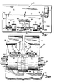
- a welding station 10 includes a base plate 12 supporting a motor 14 connected to a drive shaft 16 journalled for rotation within bearings 18.
- a pair of drive pulleys 20 and 22 are secured to the drive shaft 16.
- the drive pulley 20 is connected by belt 23 to a driven pulley 24 secured to the end of a half-shaft 26 supported for rotation between a pair of bearings 28, only one of which is shown.
- a chuck 30 is secured to the other end of the half-shaft 26.
- the other driven pulley 22 is connected by a belt 32 to a driven pulley 34 on another half-shaft 36 which is supported for rotation between a pair of bearings 38, only one of which is shown.
- a chuck 40 is provided on the other end of the half-shaft 36.
- the opposing half-shafts 26 and 36 are rotatable about a common axis, and the respective chucks 30 and 40 are adapted for driving engagement with elongated workpieces such as sections of tubing, pipe, rods and the like.
- elongated workpieces such as sections of tubing, pipe, rods and the like.
- one section of tube 42 is coupled to the left chuck 40 while another section of tube 44 is coupled to the right chuck 30.
- a pair of support blocks 46 and 48 are also mounted on the plate 12 for supporting the shielding system 50 of the invention during circumferential welding or heat treatment of the tubes 42 and 44.
- the shielding system 50 is adapted to enclose the areas of the rotating tubes 42 and 44 adjacent the welding or process zone and flood the space therebetween with inert gas to prevent undesirable air contamination and thereby achieve better welds of higher reliability.
- the shielding system 50 of the invention will be described herein with particular application to welding, it will be understood that the invention can also be utilized in heat treating or other processes where air contamination is undesirable.
- FIG. 2 shows the shielding system of the invention separated out from the welding station 10 of Figure 1.
- the system 50 includes a pair of generally cylindrical shields 52 and 54 which are located in longitudinally spaced apart relationship around the tubes 42 and 44.
- Each of the shields 52 and 54 includes a central opening through which tubes 42 and 44 extend in predetermined spaced apart clearance therein.
- the shields 52 and 54 are similar in construction except that shield 52 is of left hand orientation and shield 54 is of right hand orientation.
- a slotted lug 56 is secured to the top of the left shield 52 by screws 58, and a second set of screws 60 secure the lug and shield to the associated support block 46.
- the right hand shield 54 is similarly secured to its associated support block 48 by means of lug 62 and screws 64 and 66.
- the support blocks 46 and 48 are longitudinally spaced apart to define a generally upright radially extending gap 68 for the welding torch or laser beam (not shown).
- the shields 52 and 54 of system 50 are spaced apart relative to each other and relative to their respective tubes 42 and 44 to define spaces adjacent to the process zone which are continuously and uniformly flooded with inert gas at positive pressure during welding.
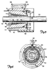
- FIGs 3-5 illustrate further constructional details of the shielding system 50.
- the shields 52 and 54 are symmetrical and therefore only one shield will be described in detail herein, it being understood that the other shield is of opposite orientation but otherwise identical, and that two such symmetrical shields comprise the shielding system 50 herein.
- the shield 52 comprises a generally cylindrical member which can be machined or otherwise formed from any suitable material, such as stainless steel, to define two annular chambers therein.
- a first annular chamber 70 is formed in the end of shield 52 adjacent the opposite shield 54.
- the chamber 70 is connected by inlet conduits 72 to external fittings 74 provided on the opposite end of the shield 52.
- inlet conduits 72 and fittings 74 are provided at equally spaced intervals about the shield 52 to facilitate even distribution of shielding gas within chamber 70.
- the inlet conduits 72 and fittings 74 are connected to a source (not shown) of inert gas such as argon.
- An annular "gas lens" or diffuser 76 is provided over the outlet side of chamber 70.
- the diffuser 76 can be of any suitable construction.
- the diffuser screen 76 can comprise five layers of no. 100 mesh size 304 stainless steel screens.
- An inside retainer ring 78 and an outside retainer ring 80 snap into corresponding grooves provided about the chamber 70 to secure the diffuser 76 in place.
- the shield 52 includes one chamber 70 having an outlet defined by an annular diffuser 76 adjacent the process zone between shields 52 and 54.
- a ring 82 is preferably provided within the first chamber 70 between the multiple inlet conduits 72 and the diffuser screen 76 to further enhance even distribution of gas within the chamber.
- the ring 82 is secured by screws 84 in position so as to deflect the gas entering the chamber 70 against an adjacent wall, thereby assuring even gas distribution within the chamber.
- the shield 52 further includes a second annular chamber 86 formed into the opposite end and inner wall, surrounding the associated tube 42 and extending away from the process zone. As illustrated, the chamber 86 is closed at the outside end by ring 88, while a cylindrical gas lens or diffuser 90 is provided over the outlet side of the chamber.
- the diffuser 90 can be of any suitable construction.
- the diffuser 90 can comprise densified porous material such as felt metal of 60% density.
- the diffuser 90, end ring 88, and shield 52 are welded together.
- An inlet conduit 92 extends from the chamber 86 to external fittings 94, which in turn are connected to a source (not shown) of inert gas such as argon.
- three inlet conduits 92 and fittings 94 are provided at equally spaced intervals about the end of shield 52 to facilitate even distribution of shielding gas within chamber 86.
- the second chamber 86 is preferably filled with suitable diffuser material, such as fine stainless steel- or nickel wool, with the notched outlet ends of the gas conduits 92 being oriented outwardly as is best seen in Figure 3, to deflect the gas against the adjacent wall of the chamber, in order to further enhance even distribution of gas therein.
- suitable diffuser material such as fine stainless steel- or nickel wool
- FIGS 6 and 7 contain schematic illustrations of the shielding system 50 herein, which operates as follows.
- the shield 54 is symmetrical but otherwise identical in construction to the shield 52 described above. Accordingly, for purposes of clarity, the identical components of shield 54 have been denoted with the same reference numerals utilized in connection with the description of shield 52, but have' been differentiated therefrom by means of prime (') notations. Assume that tubes 42 and 44 are positioned end-to-end as shown and that a welding nozzle or laser beam is in place above the space 68 between shields 52 and 54.
- inlets 74 and 74' of chambers 70 and 70' are connected to a source of inert gas under pressure
- the inlets 94 and 94' of the second chambers 86 and 86' are also connected to a source of inert gas under pressure such that the chambers are positively pressurized and inert gas flows outwardly through diffusers 76, 76', 90 and 90' as indicated by the arrows.
- chambers 86 and 86' are pressurized to a predetermined level above atmosphere, such as about 3 2 kg/cm 2 , some of the inert gas from these chambers travels outwardly through the annular space along tubes 42 and 44, respectively, while the remainder of the gas from these chambers flows inwardly through this annular space toward the circumferential space or process zone between the shields. Simultaneously, substantially all of the inert gas from chambers 70 and 70' flows into this circumferential space between shields 52 and'54 and radially outward to form a blanket of inert gas surrounding the joint 96 between tubes 42 and 44. As illustrated, the joint 96 comprises a butt joint, however, it will be understood that the shielding system 50 of the invention can be utilized with various other types of joints including overlapping joints, etc.
- a longitudinally -slotted sleeve 98 is provided over the adjacent ends of shields 52 and 54 in order to approximate a closed circumferential chamber.
- the sleeve 98 is slotted or otherwise provided with an access opening for the welding nozzle (not shown).
- the slotted sleeve 98 can be formed from suitable plastic or aluminum, with substantially transparent plastic being preferred for visibility during the welding operation.
- the shielding system 50 can be provided with an adjustable guiding tube 100 for directing a jet of inert gas towards the thermally excited region along joint 96.
- the use of the adjustable guiding tube 100 is particularly useful when the shielding system 50 is utilized with a laser welder.
- the high power density of laser beams causes metals to vaporize, creating "plasma” or "plume” which are highly absorptive to laser beams. Usage of the adjustable guiding tube 100 for blowing away the plasma with a jet of inert gas is therefore desirable.
- the tube 100 includes a straight elongate portion extending through a longitudinal package in the shield 52, and a generally L-shaped discharge and extending into the circumferential space between shields 52 and 54. The guiding tube 100 can thus be adjusted axially and rotationally to position the discharge end thereof in proper position with respect to joint 96.
- the shielding system 50 can become hot from proximity to the process zone and heat source. This can be a consideration depending upon the materials involved. If desired, the shielding system 50 can also be provided with heat sinks, fins, or internal coolant passages for cooling purposes.
- the merits of the shielding system 50 herein have been experimentally verified.
- the oxygen level in the process zone between shields 52 and 54 was consistently lowered from about 200,000 PPM, which is equivalent to the normal oxygen level in air, to about 4.5 to 8 PPM, within 30 seconds of argon purging. It should be noted that the oxygen content of the purging gas was found to be 3.5 PPM.
- Variations in flow rates through the two chambers of each shield 52 and 54 between 0.15 and 1.2 m 3 per hour, and variations in the rotational speeds of the tubes being welded up to about 238 rpm, yielded practically identical coverage of inert gas about the process zone.
- the present invention comprises an improved shielding system for circumferentially welding and heat treating tubes and the like, which system has numerous advantages over the prior art.
- the primary advantage comprises the fact that the system herein enables better welds of higher quality and reliability to be obtained by substantially complete elimination of air contamination from the welding region.
- the system herein is of relatively straightforward and compact construction, and can be used with lasers and virtually any other type of welding or heat treating processes with improved interchangability.
- the system herein facilitates the welding of metal alloys such as titanium and zirconium, which are particularly sensitive to air contamination during welding. Other advantages will be evident to those skilled in the art.
Landscapes
- Engineering & Computer Science (AREA)
- Physics & Mathematics (AREA)
- Plasma & Fusion (AREA)
- Mechanical Engineering (AREA)
- Laser Beam Processing (AREA)
- Arc Welding In General (AREA)
- Butt Welding And Welding Of Specific Article (AREA)
- Lining Or Joining Of Plastics Or The Like (AREA)
Applications Claiming Priority (2)
| Application Number | Priority Date | Filing Date | Title |
|---|---|---|---|
| US591360 | 1984-03-20 | ||
| US06/591,360 US4528436A (en) | 1984-03-20 | 1984-03-20 | High reliability double-chambered shielding system for welding |
Publications (2)
| Publication Number | Publication Date |
|---|---|
| EP0157131A2 true EP0157131A2 (de) | 1985-10-09 |
| EP0157131A3 EP0157131A3 (de) | 1986-10-08 |
Family
ID=24366181
Family Applications (1)
| Application Number | Title | Priority Date | Filing Date |
|---|---|---|---|
| EP85101646A Ceased EP0157131A3 (de) | 1984-03-20 | 1985-02-15 | Hochzuverlässiges Zweikammer-Abschirmsystem zum Schweissen |
Country Status (4)
| Country | Link |
|---|---|
| US (1) | US4528436A (de) |
| EP (1) | EP0157131A3 (de) |
| JP (1) | JPS60213355A (de) |
| ES (1) | ES8700110A1 (de) |
Cited By (3)
| Publication number | Priority date | Publication date | Assignee | Title |
|---|---|---|---|---|
| FR2602444A1 (fr) * | 1986-08-11 | 1988-02-12 | Fmc Corp | Procede et appareil de reglage d'une atmosphere de soudage |
| FR2655898A1 (fr) * | 1989-12-15 | 1991-06-21 | Electricite De France | Procede et dispositif de soudage bout a bout de deux elements tubulaires en alliage metallique. |
| GB2243483A (en) * | 1990-04-11 | 1991-10-30 | Bicc Plc | Mineral insulated cable manufacture |
Families Citing this family (21)
| Publication number | Priority date | Publication date | Assignee | Title |
|---|---|---|---|---|
| US5257732A (en) * | 1991-03-13 | 1993-11-02 | Praxair Technology, Inc. | Laminar barrier inert fluid shield apparatus |
| US5152453A (en) * | 1991-03-13 | 1992-10-06 | Praxair Technology, Inc. | Laminar barrier inerting for leading and/or trailing shield in welding application |
| US5390846A (en) * | 1993-08-11 | 1995-02-21 | Thode; Jonathan E. | Welding gas purging apparatus and method |
| US5484973A (en) * | 1994-10-20 | 1996-01-16 | Praxair Technology, Inc. | Underbead weld shield method and apparatus |
| GB9701161D0 (en) * | 1997-01-21 | 1997-03-12 | Agais Offshore Ltd | Apparatus and method for welding and inspecting coiled tubing |
| JP3971864B2 (ja) * | 1999-04-02 | 2007-09-05 | 大陽日酸株式会社 | ステンレス鋼配管の接合方法 |
| US6809286B2 (en) * | 2002-08-16 | 2004-10-26 | Illinois Tool Works Inc. | Shielding gas filter for welding apparatus |
| JP2005217119A (ja) * | 2004-01-29 | 2005-08-11 | Matsushita Electric Ind Co Ltd | レーザ発振装置 |
| US7013104B2 (en) | 2004-03-12 | 2006-03-14 | Lexmark International, Inc. | Toner regulating system having toner regulating member with metallic coating on flexible substrate |
| US7345256B2 (en) * | 2004-04-08 | 2008-03-18 | Ziyun Chen | Methods and apparatus for delivering laser energy for joining parts |
| US7236729B2 (en) | 2004-07-27 | 2007-06-26 | Lexmark International, Inc. | Electrophotographic toner regulating member with induced strain outside elastic response region |
| US7667157B2 (en) * | 2004-09-29 | 2010-02-23 | General Electric Company | Portable plenum laser forming |
| US20090148719A1 (en) * | 2007-12-07 | 2009-06-11 | Alcoa Inc. | Friction-stir weldments and systems and methods for producing the same |
| DE102012217082B4 (de) * | 2012-09-21 | 2016-06-16 | Trumpf Laser Gmbh | Laserbearbeitungskopf mit einer Ringdüse |
| JP2015217524A (ja) * | 2014-05-14 | 2015-12-07 | 株式会社カネカ | 冷却冶具 |
| CN104384706B (zh) * | 2014-11-26 | 2016-03-23 | 哈尔滨工业大学 | 一种钛及钛合金搅拌摩擦焊用三层气体保护罩 |
| DE102016118109A1 (de) * | 2016-09-26 | 2018-03-29 | Newfrey Llc | Fügeverfahren zum vorlochfreien Verbinden von wenigstens einem ersten Bauteil mit einem zweiten Bauteil |
| US20220234131A1 (en) * | 2021-01-27 | 2022-07-28 | Airgas, Inc. | Apparatus for pipe purging |
| JP7593237B2 (ja) * | 2021-06-02 | 2024-12-03 | 株式会社Ihi | 接合部カバー |
| WO2024052904A1 (en) * | 2022-09-06 | 2024-03-14 | Magnus Metal Ltd. | Laminar flow localized protective atmosphere for additive casting |
| US12420351B1 (en) * | 2025-02-27 | 2025-09-23 | Travis Field | Portable purge chamber for controlled atmosphere welding of readily contaminated metals like titanium or zirconium |
Family Cites Families (13)
| Publication number | Priority date | Publication date | Assignee | Title |
|---|---|---|---|---|
| US2611848A (en) * | 1950-05-25 | 1952-09-23 | Smith Oliver Ross | Radiant heat welding equipment |
| US2903559A (en) * | 1953-12-21 | 1959-09-08 | Wempe Bernhard | Torch for arc-welding |
| US2868950A (en) * | 1956-11-13 | 1959-01-13 | Union Carbide Corp | Electric metal-arc process and apparatus |
| FR1251989A (fr) * | 1960-03-28 | 1961-01-20 | Siemens Ag | Dispositif de chauffage par induction de matériaux en forme de barres ou de tubes |
| GB1254889A (en) * | 1968-04-01 | 1971-11-24 | Ind Magnetics Inc | Forming method |
| US3652818A (en) * | 1970-07-31 | 1972-03-28 | Continental Can Co | Inert atmosphere seam welder |
| US3875364A (en) * | 1973-04-23 | 1975-04-01 | Dallas T Boyett | Apparatus for inert gas shielded welding |
| US4000392A (en) * | 1974-07-01 | 1976-12-28 | United Technologies Corporation | Fusion zone purification by controlled laser welding |
| US4278868A (en) * | 1977-12-19 | 1981-07-14 | Thermatool Corp. | Methods and apparatus for heating metal parts with magnetically driven travelling electric arc |
| US4278864A (en) * | 1979-02-21 | 1981-07-14 | Claude De Facci | Welding gas shield control |
| JPS5750147U (de) * | 1980-09-09 | 1982-03-20 | ||
| JPS5754939U (de) * | 1980-09-18 | 1982-03-31 | ||
| FR2504042A1 (fr) * | 1981-04-15 | 1982-10-22 | Safial | Machine pour souder sous atmosphere gazeuse des elements longiformes en particulier des tubes en titane |
-
1984
- 1984-03-20 US US06/591,360 patent/US4528436A/en not_active Expired - Fee Related
-
1985
- 1985-02-15 EP EP85101646A patent/EP0157131A3/de not_active Ceased
- 1985-03-13 ES ES541209A patent/ES8700110A1/es not_active Expired
- 1985-03-19 JP JP60053532A patent/JPS60213355A/ja active Granted
Cited By (4)
| Publication number | Priority date | Publication date | Assignee | Title |
|---|---|---|---|---|
| FR2602444A1 (fr) * | 1986-08-11 | 1988-02-12 | Fmc Corp | Procede et appareil de reglage d'une atmosphere de soudage |
| FR2655898A1 (fr) * | 1989-12-15 | 1991-06-21 | Electricite De France | Procede et dispositif de soudage bout a bout de deux elements tubulaires en alliage metallique. |
| GB2243483A (en) * | 1990-04-11 | 1991-10-30 | Bicc Plc | Mineral insulated cable manufacture |
| GB2243483B (en) * | 1990-04-11 | 1994-08-10 | Bicc Plc | Mineral insulated cable manufacture |
Also Published As
| Publication number | Publication date |
|---|---|
| JPS60213355A (ja) | 1985-10-25 |
| ES8700110A1 (es) | 1986-10-01 |
| US4528436A (en) | 1985-07-09 |
| JPS6359798B2 (de) | 1988-11-21 |
| ES541209A0 (es) | 1986-10-01 |
| EP0157131A3 (de) | 1986-10-08 |
Similar Documents
| Publication | Publication Date | Title |
|---|---|---|
| US4528436A (en) | High reliability double-chambered shielding system for welding | |
| US4172974A (en) | Underwater welding apparatus | |
| US6881919B2 (en) | Powder feed nozzle for laser welding | |
| US20050056628A1 (en) | Coaxial nozzle design for laser cladding/welding process | |
| US5667706A (en) | Apparatus and method for laser welding the inner surface of a tube | |
| US4694137A (en) | Laser welding head for sleeve-to-tube welding | |
| US4018973A (en) | Furnace construction for plasma arc remelting of metal | |
| KR20000029905A (ko) | 용접방법 | |
| US4803335A (en) | Gas shroud and method | |
| EP0020845B1 (de) | Plasmabrenner | |
| US4365136A (en) | Zone refinement of inertia welded tubulars to impart improved corrosion resistance | |
| KR19990083202A (ko) | 내부면의 레이저 가공 방법 및 장치 | |
| US4110590A (en) | Inert gas welding | |
| SE8300546L (sv) | Svetspistol | |
| US3980802A (en) | Method of arc control in plasma arc furnace torches | |
| EP0025989B1 (de) | Wolfram-Gasbogenschweissbrenner und Schweissverfahren | |
| JPH031110B2 (de) | ||
| US4345744A (en) | Working machine with flame cutter and cooling unit | |
| US5406047A (en) | Plasma torch for melting material to be processed in a container and for maintaining the material at the required temperature | |
| JPS61119383A (ja) | イナ−トガスタングステンア−ク溶接法 | |
| EP0238171A1 (de) | Laserschweisskopf zum Verschweissen einer Muffe mit einem Rohr | |
| KR840001978Y1 (ko) | 개스 텅스텐 아아크 용접 토오치 | |
| JP4628353B2 (ja) | スロット付き坑井ライナの熱的バリ除去装置および方法 | |
| CA1068353A (en) | Automatic seal welding apparatus | |
| JPS6160757B2 (de) |
Legal Events
| Date | Code | Title | Description |
|---|---|---|---|
| PUAI | Public reference made under article 153(3) epc to a published international application that has entered the european phase |
Free format text: ORIGINAL CODE: 0009012 |
|
| AK | Designated contracting states |
Designated state(s): BE DE FR GB IT SE |
|
| PUAL | Search report despatched |
Free format text: ORIGINAL CODE: 0009013 |
|
| RHK1 | Main classification (correction) |
Ipc: B23K 9/32 |
|
| AK | Designated contracting states |
Kind code of ref document: A3 Designated state(s): BE DE FR GB IT SE |
|
| 17P | Request for examination filed |
Effective date: 19870320 |
|
| 17Q | First examination report despatched |
Effective date: 19880712 |
|
| STAA | Information on the status of an ep patent application or granted ep patent |
Free format text: STATUS: THE APPLICATION HAS BEEN REFUSED |
|
| 18R | Application refused |
Effective date: 19890102 |
|
| RIN1 | Information on inventor provided before grant (corrected) |
Inventor name: STOL, ISRAEL |