EP0157176A2 - Appareil pour mesurer des dimensions, en particulier des dimensions diamétrales et axiales de parts à symétrie rotationelle - Google Patents
Appareil pour mesurer des dimensions, en particulier des dimensions diamétrales et axiales de parts à symétrie rotationelle Download PDFInfo
- Publication number
- EP0157176A2 EP0157176A2 EP85102210A EP85102210A EP0157176A2 EP 0157176 A2 EP0157176 A2 EP 0157176A2 EP 85102210 A EP85102210 A EP 85102210A EP 85102210 A EP85102210 A EP 85102210A EP 0157176 A2 EP0157176 A2 EP 0157176A2
- Authority
- EP
- European Patent Office
- Prior art keywords
- slide
- slides
- measuring
- dimensions
- signals
- Prior art date
- Legal status (The legal status is an assumption and is not a legal conclusion. Google has not performed a legal analysis and makes no representation as to the accuracy of the status listed.)
- Granted
Links
Images


Classifications
-
- G—PHYSICS
- G01—MEASURING; TESTING
- G01B—MEASURING LENGTH, THICKNESS OR SIMILAR LINEAR DIMENSIONS; MEASURING ANGLES; MEASURING AREAS; MEASURING IRREGULARITIES OF SURFACES OR CONTOURS
- G01B21/00—Measuring arrangements or details thereof, where the measuring technique is not covered by the other groups of this subclass, unspecified or not relevant
- G01B21/02—Measuring arrangements or details thereof, where the measuring technique is not covered by the other groups of this subclass, unspecified or not relevant for measuring length, width, or thickness
-
- G—PHYSICS
- G01—MEASURING; TESTING
- G01B—MEASURING LENGTH, THICKNESS OR SIMILAR LINEAR DIMENSIONS; MEASURING ANGLES; MEASURING AREAS; MEASURING IRREGULARITIES OF SURFACES OR CONTOURS
- G01B5/00—Measuring arrangements characterised by the use of mechanical techniques
- G01B5/004—Measuring arrangements characterised by the use of mechanical techniques for measuring coordinates of points
- G01B5/008—Measuring arrangements characterised by the use of mechanical techniques for measuring coordinates of points using coordinate measuring machines
Definitions
- the present invention relates to an apparatus for measuring dimensions, in particular diametral and axial dimensions of parts with rotational symmetry arranged on a support, with a support structure, a system of slides with a first slide movable with respect to the support structure along a longitudinal axis and a second slide movable along a transversal direction, transducer means adapted to provide signals responsive to the positions of the slides, measuring means carried by the system of slides, and processing means adapted to receive the signals of the transducer means and the signals of the measuring means for combining them.
- This type of apparatus is very fast and accurate, but scarcely flexible in its range of applications, because the heads are arranged according to a substantially rigid disposition, for the comparative checking of a determined type of part.
- An apparatus in particular a coordinate measuring machine, in accordance with the prior art portion of claim 1 is also known from British patent application N. 2112140.
- the machine described in British patent application N. 2112140 that - on the contrary - is also intended for measurements in manufacturing shops, comprises a support structure, a system of three slides movable with respect to the support structure along three perpendicular axes, transducer means including incremental linear transducers adapted to detect the positions of the slides with respect to the support structure, measuring means constituted by a measuring head carried by one of the slides and having a feeler for performing measurements along said three perpendicular axes, control means comprising electric motors and driving devices for controlling the displacements of the slides according to a program, and processing means connected to the linear transducers and the measuring head for determining the dimensions of the part as a combination of the relevant signals of the linear transducers and of the measuring head.
- the parts are transferred from the manufacturing line to a round table of the measuring machine, that can be differently oriented.
- This coordinate measuring machine is evidently very flexible, since it may check parts of very different types, but is rather slow because, for example, checking a diameter requires at least two touches of the feeler. Moreover, in order to obtain accurate measurements it is indispensable that during the measurement cycle the part remain perfectly stationary, or anyway in exactly known positions with respect to the machine; to this end, as already mentioned, the part is taken away from the manufacturing line and is loaded onto the round table of the measuring machine. If the machine were used for checking parts arranged in a manufacturing line, for example onto a pallet conveyor, possible settlings or vibrations of the pallet, e.g. during the displacements of the slides necessary for subsequently bringing the feeler into contact with diametrically opposite points of a round part, might cause unacceptable errors.
- Object of the present invention is to realize an apparatus adapted to measure dimensions, such as diameters and axial distances of parts with rotational symmetry, that guarantee a favourable compromise between the features of the multidimensional gauges and those of the coordinate measuring machines.
- the invention as characterized by claim N. 1 solves the problem of obtaining an apparatus adapted to dimensional checking in manufacturing shops and that is capable of checking, with good speed, accuracy and repeatability, dimensions lying within a broad variation range, without requiring a strictly stable and accurate positioning of the part.
- every diameter measurement can be substantially obtained through a single mutual displacement of the two slides carrying the two measuring heads and every measurement of axial dimensions can be performed through the simultaneous use of the same measuring heads.
- the main advantages offered by the present invention reside basically in that the measurements relating to diameters are substantially unaffected by the small positioning errors and the limited settlings of the part support which may occurr when the part is arranged in a manufacturing line, and in that for each measurement of axial dimensions it is possible to compensate errors caused by a possible inclination of the part axis with respect to the longitudinal axis of the apparatus.
- a housing 2 fixed to a support structure 1, having a bridge shape, is a housing 2 internally housing a movable element or slide 3.
- Slide 3 can slide along to the ⁇ Y vertical direction, i.e. the longitudinal geometric axis of the apparatus, along two guide elements 4 and 5, fixed to the walls of housing 2, through suitable sliding devices schematically shown in the figure and indicated by reference numerals 6 and 7.
- a threaded spindle 8, parallel to guide elements 4 and 5, has its lower end mounted, through thrust bearings - not shown - onto the lower base of housing 2 and its upper end - coming out from housing 2 via a through hole 9 obtained in the upper base of housing 2 - coupled to an electric motor 10 that is fixed to the upper base of housing 2.
- the section of spindle 8 housed within housing 2 partially engages a threaded bushing 11 fixed to slide 3.
- Two vertical columns 12 and 13 fixed to slide 3 pass through the lower base of housing 2 via two through holes 14 and 15.
- the lower bases of columns 12 and 13, that are arranged externally with respect to housing 2 are fixed to a movable support member 16 substantially constituted by two flat elements or plates 17 and 18, rigidly connected in positions parallel to each other by a third element or plate 19, perpendicular to the first two elements, that is better visible in figure 2.
- a belt 20 Arranged between elements 17 and 18 is a belt 20 that closes about two pulleys 21 and 22.
- Driving pulley 21 is keyed onto a hub 23 that has an end coupled to plate 18 - through bearings not shown - in such a way as to be free to rotate about its axis and the other end - passing through plate 17 via a through hole 25 - coupled to an external electric motor 24.
- Driven pulley 22 is idle onto a pin 26 having its ends fixed to plates 17 and 18 in a way (not shown in the figure) adjustable along a direction transversal with respect to the axis of pin 26, for permitting adjustment of the tension of belt 20.
- Slides 27 and 28 Fixed to belt 20 on opposite sides with respect to the plane defined by the axes of hub 23 and pin 26 are two movable elements, or horizontal slides 27 and 28. Slides 27 and 28, that consequently are coupled to a common driving device (belt 20), can translate along the ! X transversal direction, i.e. along a horizontal geometric axis, and respectively carry, by means of connecting elements passing through an opening 29 of plate 18, measuring means constituted by two measuring heads 30 and 31, that comprise movable arms 32 and 33, whereto are fixed feelers 34 and 35. Arms 32 and 33 can perform angular and axial displacements permitting feelers 34 and 35 to displace substantially along the +X, -X, +Y and -Y directions.
- Slides 27 and 28 rest upon guide devices constituted by a plurality of rollers fixed to plate 18 so that they can rotate about their axes; one of said rollers, indicated by reference numeral 36, is shown, as an example, in figure 1.
- part 38 Arranged on a support or rest 37 is the part 38, having rotational symmetry, of which it is desired to check internal and external diameters, and axial sizes, or depths. Part 38, depending also on its weight, can be simply laid on suitable datums of support 37, or locked by suitable clamping devices.
- support 37 can be constituted by a pallet of a pallet conveyor 39 - shown very schematically -, moving step-wise.
- Pallet conveyor 39 is arranged on a basement 40 on which rest, through suitable pedestals 41, 42, the stanchions of support structure 1.
- the stanchions of bridge structure 1 are symmetrically arranged on the two sides of conveyor 39 and support 37, this being advantageous for limiting the influence of yieldings of basement 40 on the mutual position of conveyor 39 and bridge structure 1.
- the apparatus comprises a cabinet 43 in which are contained input/output circuits 44, a computer numerical control (CNC) 45 and a programmable controller 46.
- CNC computer numerical control
- Input/output circuits 44 are connected, among other things, to motors 10 and 24, to measuring heads 30, 31 and to transducer means constituted by two incremental linear transducers 47, 48 (fig. 3).
- Linear transducer 47 of the optical scale type, is preferably arranged so as to define a geometric axis coinciding with the central axis of the apparatus and comprises a graduated scale 49 fastened to housing 2 and a slider 50 fixed to slide 3.
- Linear transducer 48 comprises a graduated scale 51 fastened to slide 27 and a slider 52 fixed to slide 28.
- the transducer and measuring means, the motor and control means and processing means of the apparatus are schematized in the functional simplified diagram of figure 3.
- the diagram of fig. 3 illustrates the functions of some of the circuits contained in cabinet 43 with reference to the checking of an internal diameter.
- Linear transducer 47 is connected to a counter 53 that is connected to a group 54 for driving motor 10.
- Linear transducer 48 is connected, through a counter 55, to a group 56 for driving motor 24.
- Groups 54 and 56 are controlled depending on the program loaded into numerical control 45.
- the output signals of measuring heads 30 and 31 reach, through two amplifiers 57, 58, an analogue summing circuit 59.
- the output of analogue summing circuit 59 is connected to group 56, to the input of an analog to digital converter 60 and to a comparator or enabling circuit 61 having another input connected to a circuit 62 providing a reference voltage.
- a digital adding circuit 63 has three inputs - respectively connected to the outputs of counter 55, of converter 60 and of an adjustment circuit 64 - and an output connected to a latch circuit 65.
- Circuit 65 has an output connected to a display unit 66.
- the first slide 3 In rest position, the first slide 3 is at the upper limit of its stroke (i.e. it can only displace along the -Y direction), while horizontal slides 27 and 28 are in the position of maximum approach (i.e. feelers 34 and 35 are at the minimum mutual distance).
- the apparatus is started by the relevant keyboard of cabinet 43 and a zero-setting operation on a master part is performed. Then, by acting again on the keyboard, the measurement operation is initiated, by causing starting of motor 10 that, through threaded spindle 8, controls translation of slide 3 along the -Y direction, until feelers 34 and 35 are arranged in correspondence with the cross-section of part 38 the diameter of which must be checked.
- motor 24 is actuated and, by causing rotation of driving pulley 21 and consequently motion of belt 20, moves slides 27 and 28 away from each other by displacing them along the -X and +X directions, respectively.
- the mutual position of slides 27 and 28 - that are always arranged symmetrically with respect to the longitudinal geometric axis of the apparatus and to the geometric axis of part 38 - is detected by linear transducer 48.
- Driving group 56 depending on the value of the output signal of summing circuit 59, controls a deceleration and then the stop of motor 24, as will be more clearly described with reference to fig. 4.
- This measurement signal is detected and stored by latch circuit 65, that is enabled by comparator 61, as will be explained with reference to figure 4.
- circuit 65 is displayed by unit 66 and possibly recorded through a printer arranged in cabinet 43.
- the diagram of fig. 4 shows, in analogue form, the variations of the output signals of amplifiers 57, 58, of counter 55 (the digital signal of counter 55 is shown in analogue form for convenience of illustration) and the sum of these three analogue signals, under the following hypotheses.
- Line “a” represents the value of the output signal of counter 55
- broken lines “b” and “c”, partially superimposed, represent, respectively, the values of the output signals of amplifiers 57 and 58
- broken line “d” represents the sum of the corresponding values of signals "a", "b", "c”.
- the output signal of analogue summing circuit 59 is utilized by group 56 for controlling a deceleration, and subsequently the stop, of motor 24.
- the deceleration is controlled (with a certain delay) when the first of feelers 34, 35 - in the case of fig. 4, feeler 34 - comes into contact with part 38, and the stop (it, too, with a certain delay) when both feelers 34, 35 are into contact with part 38. In this way it is possible to prevent damages of measuring heads 30, 31 and take the diameter measurement when the speed of slides 27, 28 is reduced.
- the apparatus can perform diameter measurement in dynamic conditions, too, i.e. when slides 27, 28 are in motion.
- comparator 61 is built so as to provide a triggering signal when the values of signals "b", "c" at the outputs of amplifiers 57 and 58 have values T I , T 2 the sum of which, T 1 + T 2 , is equal to zero. This corresponds to the distance 1 3 indicated in the abscissae in the diagram of fig. 4.
- FIG. 5 is similar to that of figure 3 and comprises the same circuit blocks, indicated by the same reference numerals of figure 3, since they refer to similar functions. The main differences are as follows.
- Driving group 56 receives, as control signal, only the signal from counter 55 (and therefore drives motor 24 only depending on the program loaded into numerical control 45 and on the signal of transducer 48); driving group 54 has another control terminal connected to the output of analogue summing circuit 59; arranged between circuit 59 and converter 60 is a dividing circuit 68 adapted to divide by two the value of the input signal and a processing circuit 69 is arranged between latch circuit 65 and display unit 66.
- correction value provided by adjustment circuit 64 and the reference voltage provided by circuit 62 may have different values from those present during the cycle for internal diameter checking.
- the apparatus is zero-set on a master part, for adapting it to the measurement of axial dimensions.
- the zero-setting operations may be carried out - rather then on different master parts - on a single master of suitable shape, for example spherical, that can be permanently arranged in the apparatus.
- part 38 is affected by an angular positioning error (due, for example, to a lack of accuracy in the orientation of support 37), owing to which the geometric axis of part 38 and the longitudinal axis of the apparatus form an angle or different from zero, as shown in figure 6, where the error o( is manifestly exaggerated, for clarity of illustration, with respect to what can happen in practice.
- motor 24 actuates horizontal slides 27, 28 so as to arrange feelers 34, 35 at a suitable distance, depending on the dimensions of support 37 and on the nominal dimensions of part 38.
- feelers 34, 35 at a suitable distance, depending on the dimensions of support 37 and on the nominal dimensions of part 38.
- the apparatus can measure different types of parts, depending on relevant programs loaded in numerical control 45.
- the type of part that arrives into the measurement position is identified by devices of known type (e.g. video-cameras, proximity sensors, etc.) and consequently the corresponding program of numerical control 45 is automatically selected.
- the controller of the loading device transmit a code identifying the part.
- motor 10 displaces slide 3 along the -Y direction until one of feelers 34, 35 (feeler 35, in the case of figure 6) touches a suitable datum on support 37.
- Group 54 by detecting (for example, through a differentiating circuit and a comparator circuit) the variation of the output signal of summing circuit 59, can thereafter control a deceleration of motor 10.
- the output signal of adding circuit 63 remains constant.
- Circuit 65 enabled by comparator circuit 61 in a manner similar to that described with reference to figure 3, detects and stores this signal, that is also received by processing circuit 69, which in its turn memorizes it. Since at the output of circuit 68 there is half of the sum of the output signals of amplifiers 57, 58, the reference level thus determined is referred to the longitudinal axis of the apparatus, i.e. to the geometrical axis of part 38 (since the positioning error o( is negligible on this regard).
- Motor 10 stops and then inverts its direction of rotation, displacing slide 3 along the +Y direction for a determined amount.
- Therafter motor 24 is actuated and causes suitable approach of heads 30 and 31.
- motor 10 makes again slide 3 displace along the -Y direction until feelers 34 and 35 (feeler 35 first and then feeler 34, in the case of fig. 6) come into contact with the upper base of part 38.
- the measurement of this height takes place in a way similar to what described above.
- the relevant signal is memorized by processing circuit 69 and compared with the previously memorized reference signal so as to obtain the height of part 38, that is displayed by unit 66.
- This measurement cycle has the advantage that, due to the use of two measuring heads 30 and 31, it is possible to refer the measured axial distance to the axis of the apparatus.
- a considerably longer measurement cycle would be necessary, and this would increase the possibility of errors caused by settlings of the part during the measurement cycle.
- cycles of measurement of several internal and external diameters and of axial dimensions of a part may be sequentially controlled, through a relevant program, by numerical control 45.
- numerical control 45 it is possible to program the measurement operation by reducing the idle times, in particular preventing return of slides 3, 27 and 28 to the rest position, between subsequent cycles.
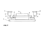
- measuring heads 30, 31 having movable arms with special shapes.
- heads 30, 31 comprise L-shaped movable arms 78, 79, that bear relevant feelers 80, 81.
- the apparatus is particularly adapted to check parts with rotational symmetry, like hubs and shafts.
- the symmetrical arrangement of horizontal slides 27, 28 and of the relevant measuring heads 30, 31 allows to perform measurements quickly and with considerable accuracy, by maintaining feelers 34, 35 or 80, 81 in a meridian plane of these types of parts.
- the apparatus may be modified accordingly, e.g. by using a first horizontal slide that carries two further slides symmetrically movable along another horizontal axis, perpendicular to the axis of the first slide.
- the measuring heads in this case too, are in their turn arranged on the second and the third slides so as to be able to check radial and longitudinal sizes of the part.
- the preferred arrangement of the slides is that shown in fig. 1, because better accuracy and repeatability of the measurements can be obtained. Therefore, whenever possible it is preferable to properly orient and support the parts so as to measure them by using the embodiment of fig. 1.
- each movable arm of the measuring heads may have a plurality of feelers for overcoming problems of accessibility of the different sections of the parts, for shortening measurement cycles, etc.
- the apparatus can be provided with further housings, covers and sealing means for protection against chips, oil and other foreign matter.
Landscapes
- Physics & Mathematics (AREA)
- General Physics & Mathematics (AREA)
- A Measuring Device Byusing Mechanical Method (AREA)
- Length Measuring Devices With Unspecified Measuring Means (AREA)
Applications Claiming Priority (2)
| Application Number | Priority Date | Filing Date | Title |
|---|---|---|---|
| IT03409/84A IT1179305B (it) | 1984-04-04 | 1984-04-04 | Apparecchiatura per la misura di dimensioni, in particolare dimensioni diametrali e assiali di pezzi a simmetria di rotazione |
| IT3409 | 1984-04-04 |
Publications (4)
| Publication Number | Publication Date |
|---|---|
| EP0157176A2 true EP0157176A2 (fr) | 1985-10-09 |
| EP0157176A3 EP0157176A3 (en) | 1987-10-28 |
| EP0157176B1 EP0157176B1 (fr) | 1989-12-13 |
| EP0157176B2 EP0157176B2 (fr) | 1996-12-18 |
Family
ID=11106666
Family Applications (1)
| Application Number | Title | Priority Date | Filing Date |
|---|---|---|---|
| EP85102210A Expired - Lifetime EP0157176B2 (fr) | 1984-04-04 | 1985-02-28 | Appareil pour mesurer des dimensions, en particulier des dimensions diamétrales et axiales de parts à symétrie rotationelle |
Country Status (5)
| Country | Link |
|---|---|
| US (1) | US4562648A (fr) |
| EP (1) | EP0157176B2 (fr) |
| JP (1) | JPS60228913A (fr) |
| DE (2) | DE157176T1 (fr) |
| IT (1) | IT1179305B (fr) |
Cited By (10)
| Publication number | Priority date | Publication date | Assignee | Title |
|---|---|---|---|---|
| EP0342267A1 (fr) * | 1987-05-23 | 1989-11-23 | Firma Carl Zeiss | Appareil de mesure des coordonnées |
| FR2644578A1 (fr) * | 1989-03-14 | 1990-09-21 | Snep Sa | Banc de mesure dimensionnel horizontal inter-exter electronique |
| EP0409267A1 (fr) * | 1989-07-21 | 1991-01-23 | PRIMA INDUSTRIE S.p.A. | Appareil et procédé de mesure automatique des dimensions des solides de révolution |
| EP0315308A3 (fr) * | 1987-09-25 | 1991-07-31 | The Timken Company | Machine de jaugeage de coordonnées cylindriques |
| FR2660066A1 (fr) * | 1990-03-21 | 1991-09-27 | Mauser Werke Oberndorf | Dispositif de mesure, en particulier pour la mesure du diametre interieur d'alesages. |
| EP0473895A1 (fr) * | 1990-09-05 | 1992-03-11 | Dr.-Ing. Höfler Messgerätebau Gmbh | Dispositif pour mesurer des pièces usinées à rotation symétrique |
| EP0464431A3 (en) * | 1990-06-25 | 1992-09-23 | Firma Carl Zeiss | Coordinate-mesuring machine of the standing-axis type |
| WO1993006431A1 (fr) * | 1991-09-19 | 1993-04-01 | System E Controls Limited | Dispositif et procede de mesure |
| WO1993014367A3 (fr) * | 1992-01-08 | 1993-09-30 | Rank Taylor Hobson Ltd | Appareil metrologique |
| US6327788B1 (en) | 1995-12-07 | 2001-12-11 | Taylor Hobson Limited | Surface form measurement |
Families Citing this family (9)
| Publication number | Priority date | Publication date | Assignee | Title |
|---|---|---|---|---|
| IT1187348B (it) * | 1985-04-01 | 1987-12-23 | Finike Italiana Marposs | Apparecchiatura per il controllo di dimensioni di pezzi meccanici |
| US4649650A (en) * | 1985-05-03 | 1987-03-17 | Westinghouse Electric Corp. | Nuclear reactor fuel assembly grid measuring method and device |
| CH667726A5 (fr) * | 1986-04-30 | 1988-10-31 | Tesa Sa | Dispositif de palpage pour un appareil autonome de mesure de grandeurs lineaires. |
| EP0877224B1 (fr) * | 1997-05-07 | 2004-01-07 | Mitutoyo Corporation | Méthode et instrument avec sonde pour mesurer les dimensions internes et externes d'un objet |
| EP1150092A3 (fr) * | 2000-04-12 | 2001-11-07 | Bidwell Corporation | Jeu de mesure pour la mesure de parties d'anneau |
| US7188429B2 (en) * | 2004-01-28 | 2007-03-13 | Haidler John W | Dimensional gage with hollow spindle |
| KR20070064355A (ko) * | 2004-10-01 | 2007-06-20 | 마포스 쏘시에타 페르 아지오니 | 기계 부품들의 크기 및/또는 기하학적 형태 체킹 장치 |
| US8749798B2 (en) * | 2011-04-14 | 2014-06-10 | The Boeing Company | Methods and systems for measuring openings using photogrammetry |
| FR3034187B1 (fr) * | 2015-03-27 | 2017-06-09 | Soc Anonyme Des Eaux Minerales D'evian Et En Abrege S A E M E | Procede et appareil de mesure d'epaisseur d'une paroi d'un recipient tel qu'un pot de yaourt |
Family Cites Families (14)
| Publication number | Priority date | Publication date | Assignee | Title |
|---|---|---|---|---|
| US2370220A (en) * | 1942-07-03 | 1945-02-27 | Sheffield Corp | Gauging device |
| IT957145B (it) * | 1972-03-03 | 1973-10-10 | Marposs App Elett | Macchina di misura per il control lo di pezzi similari aventi almeno una dimensione diversa |
| IT969124B (it) * | 1972-12-01 | 1974-03-30 | Finike Italiana Marposs | Dispositivo a grande campo per la misura di dimensioni lineari di pezzi meccanici |
| DE2302502B1 (de) * | 1973-01-19 | 1974-01-17 | Christian Prof. Dr. Hoffrogge | Komparator für Innen- und Außenmaße |
| IT1005117B (it) * | 1973-09-04 | 1976-08-20 | Finike Italiana Marposs | Apparecchiatura per la misura indiretta dello sviluppo in lun ghezza di sedi o scanalature curve in pezzi meccanici |
| IT1028663B (it) * | 1975-06-13 | 1979-02-10 | Finike Italiana Marposs | Apparecchiatura per la misura di dimensioni e o errori geometrici su un pezzo meccanico |
| FR2481445A1 (fr) * | 1980-04-23 | 1981-10-30 | Thomson Csf | Procede et dispositif de mesure de caracteristiques geometriques d'un element en materiau refringent, notamment d'un tube |
| IT1133307B (it) * | 1980-05-16 | 1986-07-09 | Finike Italiana Marposs | Apparecchiatura per il controllo geometrico e/o dimensionale di pezzi in rotazione |
| JPS57147001A (en) * | 1981-03-06 | 1982-09-10 | Mitsutoyo Mfg Co Ltd | Measuring machine for inside diameter and outside diameter |
| JPS57211001A (en) * | 1981-06-19 | 1982-12-24 | Mitsutoyo Mfg Co Ltd | Measuring device for inside diameter |
| DE3219766A1 (de) * | 1981-07-10 | 1983-01-27 | Elesta AG Elektronik, 7310 Bad Ragaz | Messeinrichtung und verwendung derselben |
| GB2112140B (en) * | 1981-12-16 | 1985-08-07 | Mauser Werke Oberndorf | Coordinate measuring machine |
| JPS58131505A (ja) * | 1982-01-30 | 1983-08-05 | Toyoda Mach Works Ltd | 多穴板測定装置 |
| DE3540649C2 (de) * | 1984-11-15 | 1993-01-14 | ELGEMA GmbH, 8057 Eching | Vorrichtung zum Messen der Profilform von zylindrischen Werkstückflächen |
-
1984
- 1984-04-04 IT IT03409/84A patent/IT1179305B/it active
-
1985
- 1985-02-28 EP EP85102210A patent/EP0157176B2/fr not_active Expired - Lifetime
- 1985-02-28 DE DE198585102210T patent/DE157176T1/de active Pending
- 1985-02-28 DE DE8585102210T patent/DE3574774D1/de not_active Expired - Fee Related
- 1985-03-01 US US06/707,144 patent/US4562648A/en not_active Expired - Lifetime
- 1985-04-04 JP JP60071857A patent/JPS60228913A/ja active Granted
Cited By (13)
| Publication number | Priority date | Publication date | Assignee | Title |
|---|---|---|---|---|
| EP0456276A1 (fr) * | 1987-05-23 | 1991-11-13 | Firma Carl Zeiss | Appareil pour mesurer les coordonnées |
| US4961267A (en) * | 1987-05-23 | 1990-10-09 | Carl-Zeiss-Stiftung | Method and apparatus for making coordinate measurements |
| EP0342267A1 (fr) * | 1987-05-23 | 1989-11-23 | Firma Carl Zeiss | Appareil de mesure des coordonnées |
| EP0315308A3 (fr) * | 1987-09-25 | 1991-07-31 | The Timken Company | Machine de jaugeage de coordonnées cylindriques |
| FR2644578A1 (fr) * | 1989-03-14 | 1990-09-21 | Snep Sa | Banc de mesure dimensionnel horizontal inter-exter electronique |
| EP0409267A1 (fr) * | 1989-07-21 | 1991-01-23 | PRIMA INDUSTRIE S.p.A. | Appareil et procédé de mesure automatique des dimensions des solides de révolution |
| FR2660066A1 (fr) * | 1990-03-21 | 1991-09-27 | Mauser Werke Oberndorf | Dispositif de mesure, en particulier pour la mesure du diametre interieur d'alesages. |
| EP0464431A3 (en) * | 1990-06-25 | 1992-09-23 | Firma Carl Zeiss | Coordinate-mesuring machine of the standing-axis type |
| EP0473895A1 (fr) * | 1990-09-05 | 1992-03-11 | Dr.-Ing. Höfler Messgerätebau Gmbh | Dispositif pour mesurer des pièces usinées à rotation symétrique |
| WO1993006431A1 (fr) * | 1991-09-19 | 1993-04-01 | System E Controls Limited | Dispositif et procede de mesure |
| US5465496A (en) * | 1991-09-19 | 1995-11-14 | System E. Controls Limited | Measuring apparatus and method |
| WO1993014367A3 (fr) * | 1992-01-08 | 1993-09-30 | Rank Taylor Hobson Ltd | Appareil metrologique |
| US6327788B1 (en) | 1995-12-07 | 2001-12-11 | Taylor Hobson Limited | Surface form measurement |
Also Published As
| Publication number | Publication date |
|---|---|
| DE157176T1 (de) | 1989-01-26 |
| EP0157176B2 (fr) | 1996-12-18 |
| IT1179305B (it) | 1987-09-16 |
| US4562648A (en) | 1986-01-07 |
| EP0157176A3 (en) | 1987-10-28 |
| IT8403409A0 (it) | 1984-04-04 |
| DE3574774D1 (de) | 1990-01-18 |
| EP0157176B1 (fr) | 1989-12-13 |
| JPH0543041B2 (fr) | 1993-06-30 |
| JPS60228913A (ja) | 1985-11-14 |
Similar Documents
| Publication | Publication Date | Title |
|---|---|---|
| US4562648A (en) | Apparatus for measuring diametral and axial dimensions | |
| US4587622A (en) | Method and apparatus for determining and correcting guidance errors | |
| US5111590A (en) | Measuring method of machine tool accuracy using a computer aided kinematic transducer link and its apparatus | |
| US4866643A (en) | Method for automatic compensation of probe offset in a coordinate measuring machine | |
| US4447959A (en) | Instrument for measuring internal dimensions | |
| EP0423307B1 (fr) | Appareil de determination de position | |
| US4879817A (en) | Checking the setting of a tool | |
| US9714881B2 (en) | Method and device for determining a machining axis | |
| US4429464A (en) | Roundness calibration standard | |
| US4030201A (en) | Method and relevant apparatus for detecting the geometrical features of mechanical workpieces, in particular for measuring the eccentricity and out-of-roundness | |
| EP0484470B1 (fr) | Procede et appareil de controle dynamique des dimensions des pieces mecaniques | |
| US3417475A (en) | Device for checking instrument accuracy and wear | |
| US4625429A (en) | Apparatus for checking the roundness of rotating parts | |
| CN216558635U (zh) | 一种快速检测轴类工件止推面长度的检具 | |
| US3206857A (en) | Inspection apparatus | |
| US4355467A (en) | Method and apparatus for checking parts of a constant velocity joint | |
| JP2935603B2 (ja) | 真直度測定機能付真円度測定装置 | |
| US4266346A (en) | Method and apparatus for gaging | |
| EP0413724B1 (fr) | Appareil et procede de controle de pieces mecaniques | |
| US7107695B2 (en) | Device and process for profile measurement | |
| Traylor | CMM Gaging | |
| EP3101384B1 (fr) | Procédé d'étalonnage pour étalonner l'axe d'entraînement d'une machine-outil | |
| US3950856A (en) | Method and relevant apparatus for measuring through mobile elements, the longitudinal development of seats of grooves in mechanical workpieces | |
| SU1219914A1 (ru) | Способ определени зазора винтового механизма задатчика и устройство дл его осуществлени | |
| US3104471A (en) | Apparatus for gauging profiles |
Legal Events
| Date | Code | Title | Description |
|---|---|---|---|
| PUAI | Public reference made under article 153(3) epc to a published international application that has entered the european phase |
Free format text: ORIGINAL CODE: 0009012 |
|
| AK | Designated contracting states |
Designated state(s): CH DE FR GB IT LI SE |
|
| RAP1 | Party data changed (applicant data changed or rights of an application transferred) |
Owner name: MARPOSS SOCIETA' PER AZIONI |
|
| PUAL | Search report despatched |
Free format text: ORIGINAL CODE: 0009013 |
|
| AK | Designated contracting states |
Kind code of ref document: A3 Designated state(s): CH DE FR GB IT LI SE |
|
| 17P | Request for examination filed |
Effective date: 19880113 |
|
| DET | De: translation of patent claims | ||
| 17Q | First examination report despatched |
Effective date: 19890217 |
|
| GRAA | (expected) grant |
Free format text: ORIGINAL CODE: 0009210 |
|
| AK | Designated contracting states |
Kind code of ref document: B1 Designated state(s): CH DE FR GB IT LI SE |
|
| PLBI | Opposition filed |
Free format text: ORIGINAL CODE: 0009260 |
|
| REF | Corresponds to: |
Ref document number: 3574774 Country of ref document: DE Date of ref document: 19900118 |
|
| ET | Fr: translation filed | ||
| 26 | Opposition filed |
Opponent name: FAG KUGELFISCHER GEORG SCHAEFER & CO. Effective date: 19891229 |
|
| ITF | It: translation for a ep patent filed | ||
| PLBI | Opposition filed |
Free format text: ORIGINAL CODE: 0009260 |
|
| 26 | Opposition filed |
Opponent name: HOMMELWERKE GMBH Effective date: 19900911 Opponent name: FAG KUGELFISCHER GEORG SCHAEFER & CO. Effective date: 19891229 |
|
| ITTA | It: last paid annual fee | ||
| PLAB | Opposition data, opponent's data or that of the opponent's representative modified |
Free format text: ORIGINAL CODE: 0009299OPPO |
|
| EAL | Se: european patent in force in sweden |
Ref document number: 85102210.3 |
|
| R26 | Opposition filed (corrected) |
Opponent name: FAG KUGELFISCHER GEORG SCHAEFER & CO. * 900911 HOM Effective date: 19891229 |
|
| PLAW | Interlocutory decision in opposition |
Free format text: ORIGINAL CODE: EPIDOS IDOP |
|
| PUAH | Patent maintained in amended form |
Free format text: ORIGINAL CODE: 0009272 |
|
| STAA | Information on the status of an ep patent application or granted ep patent |
Free format text: STATUS: PATENT MAINTAINED AS AMENDED |
|
| 27A | Patent maintained in amended form |
Effective date: 19961218 |
|
| AK | Designated contracting states |
Kind code of ref document: B2 Designated state(s): CH DE FR GB IT LI SE |
|
| REG | Reference to a national code |
Ref country code: CH Ref legal event code: AEN Free format text: MAINTIEN DU BREVET DONT L'ETENDUE A ETE MODIFIEE |
|
| ITF | It: translation for a ep patent filed | ||
| ET3 | Fr: translation filed ** decision concerning opposition | ||
| PGFP | Annual fee paid to national office [announced via postgrant information from national office to epo] |
Ref country code: GB Payment date: 20010125 Year of fee payment: 17 |
|
| PGFP | Annual fee paid to national office [announced via postgrant information from national office to epo] |
Ref country code: SE Payment date: 20010221 Year of fee payment: 17 |
|
| PGFP | Annual fee paid to national office [announced via postgrant information from national office to epo] |
Ref country code: CH Payment date: 20010302 Year of fee payment: 17 |
|
| REG | Reference to a national code |
Ref country code: GB Ref legal event code: IF02 |
|
| PGFP | Annual fee paid to national office [announced via postgrant information from national office to epo] |
Ref country code: FR Payment date: 20020221 Year of fee payment: 18 |
|
| PG25 | Lapsed in a contracting state [announced via postgrant information from national office to epo] |
Ref country code: LI Free format text: LAPSE BECAUSE OF NON-PAYMENT OF DUE FEES Effective date: 20020228 Ref country code: GB Free format text: LAPSE BECAUSE OF NON-PAYMENT OF DUE FEES Effective date: 20020228 Ref country code: CH Free format text: LAPSE BECAUSE OF NON-PAYMENT OF DUE FEES Effective date: 20020228 |
|
| PG25 | Lapsed in a contracting state [announced via postgrant information from national office to epo] |
Ref country code: SE Free format text: LAPSE BECAUSE OF NON-PAYMENT OF DUE FEES Effective date: 20020301 |
|
| PGFP | Annual fee paid to national office [announced via postgrant information from national office to epo] |
Ref country code: DE Payment date: 20020315 Year of fee payment: 18 |
|
| REG | Reference to a national code |
Ref country code: CH Ref legal event code: PL |
|
| GBPC | Gb: european patent ceased through non-payment of renewal fee |
Effective date: 20020228 |
|
| EUG | Se: european patent has lapsed |
Ref document number: 85102210.3 |
|
| PG25 | Lapsed in a contracting state [announced via postgrant information from national office to epo] |
Ref country code: DE Free format text: LAPSE BECAUSE OF NON-PAYMENT OF DUE FEES Effective date: 20030902 |
|
| PG25 | Lapsed in a contracting state [announced via postgrant information from national office to epo] |
Ref country code: FR Free format text: LAPSE BECAUSE OF NON-PAYMENT OF DUE FEES Effective date: 20031031 |
|
| REG | Reference to a national code |
Ref country code: FR Ref legal event code: ST |
|
| APAH | Appeal reference modified |
Free format text: ORIGINAL CODE: EPIDOSCREFNO |