EP0157182A1 - Corps de chauffe tubulaire - Google Patents
Corps de chauffe tubulaire Download PDFInfo
- Publication number
- EP0157182A1 EP0157182A1 EP85102309A EP85102309A EP0157182A1 EP 0157182 A1 EP0157182 A1 EP 0157182A1 EP 85102309 A EP85102309 A EP 85102309A EP 85102309 A EP85102309 A EP 85102309A EP 0157182 A1 EP0157182 A1 EP 0157182A1
- Authority
- EP
- European Patent Office
- Prior art keywords
- insulating
- insulating bead
- tubular
- bead
- tubular heater
- Prior art date
- Legal status (The legal status is an assumption and is not a legal conclusion. Google has not performed a legal analysis and makes no representation as to the accuracy of the status listed.)
- Granted
Links
- 238000010438 heat treatment Methods 0.000 title claims abstract description 36
- 239000011324 bead Substances 0.000 claims abstract description 80
- 239000011810 insulating material Substances 0.000 claims abstract description 15
- 229910052751 metal Inorganic materials 0.000 claims abstract description 4
- 239000002184 metal Substances 0.000 claims abstract description 4
- 238000012544 monitoring process Methods 0.000 claims description 11
- 239000000853 adhesive Substances 0.000 claims description 5
- 230000001070 adhesive effect Effects 0.000 claims description 5
- TWNQGVIAIRXVLR-UHFFFAOYSA-N oxo(oxoalumanyloxy)alumane Chemical compound O=[Al]O[Al]=O TWNQGVIAIRXVLR-UHFFFAOYSA-N 0.000 claims description 4
- 238000013459 approach Methods 0.000 claims description 2
- 238000005452 bending Methods 0.000 claims description 2
- 230000007704 transition Effects 0.000 claims description 2
- 238000002347 injection Methods 0.000 claims 1
- 239000007924 injection Substances 0.000 claims 1
- 229910052574 oxide ceramic Inorganic materials 0.000 claims 1
- PNEYBMLMFCGWSK-UHFFFAOYSA-N Alumina Chemical compound [O-2].[O-2].[O-2].[Al+3].[Al+3] PNEYBMLMFCGWSK-UHFFFAOYSA-N 0.000 abstract 3
- 238000003825 pressing Methods 0.000 description 11
- 238000004519 manufacturing process Methods 0.000 description 4
- 239000000463 material Substances 0.000 description 4
- 238000000034 method Methods 0.000 description 4
- 230000008569 process Effects 0.000 description 3
- 238000005476 soldering Methods 0.000 description 3
- 235000008733 Citrus aurantifolia Nutrition 0.000 description 2
- 235000011941 Tilia x europaea Nutrition 0.000 description 2
- 230000008901 benefit Effects 0.000 description 2
- 239000004571 lime Substances 0.000 description 2
- CPLXHLVBOLITMK-UHFFFAOYSA-N magnesium oxide Inorganic materials [Mg]=O CPLXHLVBOLITMK-UHFFFAOYSA-N 0.000 description 2
- 239000000395 magnesium oxide Substances 0.000 description 2
- AXZKOIWUVFPNLO-UHFFFAOYSA-N magnesium;oxygen(2-) Chemical compound [O-2].[Mg+2] AXZKOIWUVFPNLO-UHFFFAOYSA-N 0.000 description 2
- 238000005096 rolling process Methods 0.000 description 2
- 238000005406 washing Methods 0.000 description 2
- 238000003466 welding Methods 0.000 description 2
- 230000002378 acidificating effect Effects 0.000 description 1
- 230000009471 action Effects 0.000 description 1
- 238000004026 adhesive bonding Methods 0.000 description 1
- 229910010293 ceramic material Inorganic materials 0.000 description 1
- 239000003795 chemical substances by application Substances 0.000 description 1
- 229940126214 compound 3 Drugs 0.000 description 1
- 238000005336 cracking Methods 0.000 description 1
- 230000007423 decrease Effects 0.000 description 1
- 239000003599 detergent Substances 0.000 description 1
- 238000009826 distribution Methods 0.000 description 1
- 238000001125 extrusion Methods 0.000 description 1
- 230000004907 flux Effects 0.000 description 1
- 230000017525 heat dissipation Effects 0.000 description 1
- 230000006872 improvement Effects 0.000 description 1
- 238000009434 installation Methods 0.000 description 1
- 239000012212 insulator Substances 0.000 description 1
- 230000000149 penetrating effect Effects 0.000 description 1
- 230000035515 penetration Effects 0.000 description 1
- 230000002093 peripheral effect Effects 0.000 description 1
- 239000004033 plastic Substances 0.000 description 1
- 229920002545 silicone oil Polymers 0.000 description 1
- XLYOFNOQVPJJNP-UHFFFAOYSA-N water Substances O XLYOFNOQVPJJNP-UHFFFAOYSA-N 0.000 description 1
- 238000004804 winding Methods 0.000 description 1
Images



Classifications
-
- H—ELECTRICITY
- H05—ELECTRIC TECHNIQUES NOT OTHERWISE PROVIDED FOR
- H05B—ELECTRIC HEATING; ELECTRIC LIGHT SOURCES NOT OTHERWISE PROVIDED FOR; CIRCUIT ARRANGEMENTS FOR ELECTRIC LIGHT SOURCES, IN GENERAL
- H05B3/00—Ohmic-resistance heating
- H05B3/40—Heating elements having the shape of rods or tubes
- H05B3/42—Heating elements having the shape of rods or tubes non-flexible
- H05B3/48—Heating elements having the shape of rods or tubes non-flexible heating conductor embedded in insulating material
Definitions
- the invention relates to a tubular heater according to the features of the preamble of claim 1, 2 or 3.
- tubular heaters are known in which a heating coil is embedded in a jacket tube made of deformable metal in insulating material, which is connected at the connection ends with connecting bolts which have a bolt part with a larger diameter, which is embedded in the insulating material, and a bolt part with have a smaller diameter which is passed through an insulating bead inserted into the front end of the jacket tube and mechanically held by the jacket tube.
- the insulating bead should be graduated in diameter and the part of the insulating bead which has the larger diameter should be pressed in between two constrictions or pinches of the jacket tube.
- a depression is provided on the part of the connecting bolt protruding from the insulating bead, by means of which the insulating bead is pressed in the direction of the interior of the tubular heater.
- the present invention has for its object to improve tubular radiators of the type in question so that a safe mounting of the insulating bead in the jacket tube is achieved while reducing the amount of work, that the risk that the insulating bead breaks when pressing the jacket tube is reduced and that, according to a special embodiment, it is possible to accommodate a temperature sensor in the connecting end of the tubular heater.
- a heating coil 2 is arranged concentrically in the casing tube 1 of a tubular heating element and is embedded in insulating material 3, preferably magnesium oxide.
- the ends of the heating coil 2 are welded to connecting bolts 4, the diameter of which is stepped, i.e. which consist of a bolt part 5 with a larger diameter and a bolt part 6 with a smaller diameter.
- the bolt parts 6 with a smaller diameter are each inserted through the inner bore of an insulating bead 7 or 8, the diameter of the bore of the insulating bead 7 or 8 corresponding approximately to the outer diameter of the bolt part 6.
- the bolt part 5 having the larger diameter is thus seated with its gradation on the inwardly directed end face of the insulating bead 7 or 8.
- the bolt part 5 has a e.g. hexagonal cross-section so that the bolt cannot twist in the pressed insulating compound 3.
- the insulating beads 7, 8 are now through in the jacket tube pinched or rolled areas 9, 10 held.
- a push-off or pinching 11 in the pin part 6 with the smaller diameter ensures a corresponding fit of the connecting pin 4 in the insulating bead 7 or 8 and prevents the connecting pin from being pulled inwards by the elastic pull of the heating coil 2 through the insulating bead 7.8 .
- a wire coil 12 is wound tightly on the casing tube 1 and is connected to the casing tube 1 in the region of the front ends by welding or soldering at 13.
- an insulating bead shown in FIGS. 5 and 7, it consists of a tubular inner body 14, the outer diameter of which is considerably smaller than the inner diameter of the casing tube 1.
- wing-shaped flags 15 are attached in one piece at an o-angular distance of 120 that have an approximately sinusoidal cross-section. Between the flags 15, however, the inner body 14 o remains free in an area 16 of at least 50, but preferably of about 60.
- the insulating bead 7 consists of an unbreakable oxide-2 ceramic material with a compressive strength N / mm of over 1000 and a bending strength of over 200 according to DIN 40685. Preference is given to insulating beads 7, 8, which are made of highly refractory, dense aluminum oxide with a mass content of over 80 to 90% and with a raw density of about 3.3 kg / dm.
- the elasticity 3 2 modulus of the insulating bead should be over 220 x 10 N / rrm.
- An aluminum oxide such as that sold under the trade name "Hilox 880" is preferred.
- the insulating bead is graduated. It consists of an area 18 whose diameter is smaller than the inside diameter of the casing tube 1 and an area 19 whose diameter corresponds approximately to the inside diameter of the casing tube 1.
- Insulating beads 8 shown in FIGS. 8 to 10 may be used.
- the tubular heating element is then first filled with the insulating material 3, that is to say generally with magnesium oxide, the heating coil 2 with the connecting bolts 4 having already been used beforehand. After pushing the insulating beads 8 onto the bolt part 6 with the smaller diameter and fixing the same by producing the pinch 11, the insulating beads 8 are then fixed by squeezing or rolling.
- insulating beads 7 and 8 are used before the insulating material is filled in, together with the connecting bolts 6 and the heating coil 2.
- the insulating material 3 is then passed through the intermediate areas 16 filled between the wing-shaped flags 15 of the insulating bead 7. This type of production also enables residual moisture to escape from the insulating material 3. Moisture penetration is prevented by using appropriate water repellants, e.g. Prevents silicone oil or the like.
- tubular heater jacket can be pressed in the area 16, whereby the mounting of the insulating bead 7 in the tubular heater jacket 1 is significantly improved. Furthermore, the risk of breakage of the insulating bead 7 by crushing during the production of the pinching or constriction is further reduced.
- the approach of the flags 15 runs in a slope 20 of about 45.
- the transition from the area 18 to the area 19 in the embodiment according to FIGS. 8 to 10 runs at an incline 21 of approximately 30.
- the tightly wound wire coil 12 fulfills several functions.
- the production of the pinch 11 is facilitated and improved since the force applied does not act directly on the insulating bead via the relatively thin jacket tube.
- the winding of the wire helix lying in the area of the insulating bead ensures a corresponding distribution of peripheral forces.
- the surface of the casing tube is enlarged and the heat emission is improved.
- brackets, heat dissipation plates, etc. can be pressed onto the tubular heating element via cold connections.
- the insulating bead 8 is seated on a channel-shaped constriction 22. This can be weak, since in any case it prevents the insulating bead from moving towards the interior of the tubular heater.
- the region of the insulating bead with the larger diameter is, as shown, in the form of a cone 23 tapering in the direction of the tubular heater end. The pressure of the casing tube 1 against the cone 23 extends over a longer distance, so that the pressure is distributed accordingly.
- FIG. 11 The embodiment shown in FIG. 11 is generally preferred since the insulating bead 8 can be mass-produced easily and expediently and the mechanical mounting thereof in the jacket tube 1 is very satisfactory.
- the embodiment shown in Fig. 12 is suitable for special purposes.
- the insulating bead has a spherical surface 24, ie the diameter decreases from a largest average diameter both in the direction of the interior of the tubular heater and in the direction of the connection end.
- the casing tube 1 is pressed in a single pressing process, without further action constrictions 25 and 26 being created by the large-area pressing, by means of which the intermediate part 27 of the casing tube 1 is attracted to the spherical surface 24 of the insulating bead.
- the insulating bead is spared accordingly, so that breakage or cracking no longer occurs even with less break-resistant material or higher pressing pressures are used with sufficiently break-resistant material can.
- the outer surface of the insulating bead is concavely recessed at 28.
- the region 29 of the casing tube 1 is pressed into the groove formed in this way.
- a rotating pressing tool should be used or the pressing should be carried out by rotating the tubular heating element.
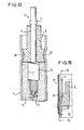
- the embodiment shown in FIG. 15 is preferred if, after soldering, a rubber cap 31 has to be applied to the end of the tubular heating element to remove the flux, which prevents the detergent from penetrating into the tubular heating element.
- the acidic agents can Otherwise form an electrically conductive layer on the insulator surface. If the diameter is chosen so that d ⁇ d ⁇ d, the gum cap 31 1 2 3 can be easily applied. It is anchored in the channel-shaped constriction 22.
- a tubular connecting element is pressed in such a way that it has a butt-conical end 34, a flat-pressed flag 35, an unpressed central shaft 36 and pressed-out tabs 37.
- the heating coil 2 is welded onto the truncated conical end 34, if necessary by means of a contactless welding technique.
- the flat-pressed flag 35 is embedded in the insulating material 3, so that the tubular connecting bolt is held against rotation. By pressing out the flag 35, a shoulder is formed, on which the insulating bead 8 is seated, and if necessary, with the interposition of an annular disc, it is pressed onto the shoulder of the flag 35 by pressing out the tabs 37.
- the jacket of the insulating bead 8 is designed in the form of a cone 23 which merges into a part with a smaller diameter via a step.
- the casing tube 1 has an annular constriction at 22 on which the insulating bead 8 sits on.
- the jacket tube is pressed against the cone of the insulating bead 8. The result is an absolutely secure connection both in the axial and in the radial direction.
- the tubular design of the connecting element has the advantage, on the one hand, that the extrusions mentioned can be produced without great effort.
- a temperature monitoring element 38 can be inserted into the tube, which has an integrated circuit, for. B. a washing machine controls.
- the temperature monitoring element z. b. consist of a PTC bead, i.e. a resistance material with a positive temperature gradient.
- the solution shown has the advantage of a very precise heat flow, namely regardless of a rotation of the tubular heater z. B. during installation.
- the one generated by the heating coil Heat flows over the frustoconical end 34, the flag 35 radially over the insulating bead 8 to the casing tube. Since the connection end of the casing tube is no longer heated, no lime deposits can form.
- the temperature monitoring element 38 which is located concentrically in the heat flow, can thus be adjusted exactly to a specific temperature of the heating coil 2, so that the power supply is switched off when this temperature is exceeded.
- the temperature monitoring element 38 can only be inserted into the tubular connecting element after completion of the tubular heating element, so that damage, for. B. when pressing the tubular heater are excluded. Is the interchangeability dispensed with and another fixation of the temperature monitoring element 38 z. B. selected by gluing, then the pressing 40 or the flag 35 can be omitted.
- the insulating bead 7 or 8 can be connected to the inner circumferential surface of the tubular heating element by means of an adhesive. Furthermore, the areas 16 between the tabs 15 of the insulating bead can be closed by an adhesive. In addition, the connecting pin 4 can be glued into the insulating bead 7 or 8. Through these measures, a frictional connection of the insulating bead with the jacket tube can be produced or improved, in particular if, for. B. lower pressures to be exerted on the jacket tube.
- the temperature monitoring element 38 provides a significant improvement in safety, e.g. against fire in devices with plastic containers, with insignificant additional effort.
Landscapes
- Resistance Heating (AREA)
Priority Applications (1)
| Application Number | Priority Date | Filing Date | Title |
|---|---|---|---|
| AT85102309T ATE39804T1 (de) | 1984-03-01 | 1985-03-01 | Rohrheizkoerper. |
Applications Claiming Priority (6)
| Application Number | Priority Date | Filing Date | Title |
|---|---|---|---|
| DE19848406445 DE8406445U1 (de) | 1984-03-01 | 1984-03-01 | Rohrheizkoerper |
| DE8406445U | 1984-03-01 | ||
| DE8413276U | 1984-04-30 | ||
| DE19848413276 DE8413276U1 (de) | 1984-04-30 | 1984-04-30 | Rohrheizkoerper mit isolierperle |
| DE8423034U | 1984-08-02 | ||
| DE19848423034 DE8423034U1 (de) | 1984-08-02 | 1984-08-02 | Rohrheizkoerper |
Publications (2)
| Publication Number | Publication Date |
|---|---|
| EP0157182A1 true EP0157182A1 (fr) | 1985-10-09 |
| EP0157182B1 EP0157182B1 (fr) | 1989-01-04 |
Family
ID=27207582
Family Applications (1)
| Application Number | Title | Priority Date | Filing Date |
|---|---|---|---|
| EP85102309A Expired EP0157182B1 (fr) | 1984-03-01 | 1985-03-01 | Corps de chauffe tubulaire |
Country Status (2)
| Country | Link |
|---|---|
| EP (1) | EP0157182B1 (fr) |
| DE (1) | DE3567347D1 (fr) |
Cited By (2)
| Publication number | Priority date | Publication date | Assignee | Title |
|---|---|---|---|---|
| EP0858084A1 (fr) * | 1997-02-07 | 1998-08-12 | I.R.C.A. S.p.a. Industria Resistenze Corazzate e Affini | Procédé de fabrication d'éléments de résistance armés et élément de résistance obtenu par ce procédé |
| CN115623616A (zh) * | 2022-11-09 | 2023-01-17 | 佛山市飞月电热科技有限公司 | 一种电热管上的绝缘结构 |
Citations (4)
| Publication number | Priority date | Publication date | Assignee | Title |
|---|---|---|---|---|
| DE2451175A1 (de) * | 1974-10-28 | 1976-05-06 | Guenter Garbe | Komplexe keramik-heizelemente mit mindestens je zwei eingesinterten metallischen elektrizitaetsleitern |
| EP0010275A1 (fr) * | 1978-10-13 | 1980-04-30 | Elpag Ag Chur | Elément chauffant tubulaire |
| DE3145876A1 (de) * | 1981-11-19 | 1983-07-14 | Elpag AG Chur, 7001 Chur | Elektrisch beheiztes geraet |
| EP0086465A1 (fr) * | 1982-02-12 | 1983-08-24 | Elpag Ag Chur | Corps de chauffe tubulaire muni d'un coupe-circuit de surcharge |
-
1985
- 1985-03-01 DE DE8585102309T patent/DE3567347D1/de not_active Expired
- 1985-03-01 EP EP85102309A patent/EP0157182B1/fr not_active Expired
Patent Citations (4)
| Publication number | Priority date | Publication date | Assignee | Title |
|---|---|---|---|---|
| DE2451175A1 (de) * | 1974-10-28 | 1976-05-06 | Guenter Garbe | Komplexe keramik-heizelemente mit mindestens je zwei eingesinterten metallischen elektrizitaetsleitern |
| EP0010275A1 (fr) * | 1978-10-13 | 1980-04-30 | Elpag Ag Chur | Elément chauffant tubulaire |
| DE3145876A1 (de) * | 1981-11-19 | 1983-07-14 | Elpag AG Chur, 7001 Chur | Elektrisch beheiztes geraet |
| EP0086465A1 (fr) * | 1982-02-12 | 1983-08-24 | Elpag Ag Chur | Corps de chauffe tubulaire muni d'un coupe-circuit de surcharge |
Cited By (2)
| Publication number | Priority date | Publication date | Assignee | Title |
|---|---|---|---|---|
| EP0858084A1 (fr) * | 1997-02-07 | 1998-08-12 | I.R.C.A. S.p.a. Industria Resistenze Corazzate e Affini | Procédé de fabrication d'éléments de résistance armés et élément de résistance obtenu par ce procédé |
| CN115623616A (zh) * | 2022-11-09 | 2023-01-17 | 佛山市飞月电热科技有限公司 | 一种电热管上的绝缘结构 |
Also Published As
| Publication number | Publication date |
|---|---|
| EP0157182B1 (fr) | 1989-01-04 |
| DE3567347D1 (en) | 1989-02-09 |
Similar Documents
| Publication | Publication Date | Title |
|---|---|---|
| DE3153393C2 (fr) | ||
| DE2907975C2 (de) | Verfahren zur Herstellung eines Kunstharzisolators | |
| DE102009005481B3 (de) | Verbindungselement für Heizwendel für Rohrheizkörper sowie Herstellungsverfahren hierfür | |
| DE10029004C2 (de) | Keramikheizungs-Glühkerze | |
| DE2417347A1 (de) | Haenge- oder pendelkabel fuer galvanisierungstrommeln | |
| DE2230276A1 (de) | Zwischen- und endmuffen fuer seile und litzen | |
| DE4001790C1 (fr) | ||
| EP0157182B1 (fr) | Corps de chauffe tubulaire | |
| DE10207201A1 (de) | Pressfitting | |
| DE102009033769B4 (de) | Crimp-Verbindung zwischen Stimulationselektrode und Leitungswendel | |
| DE19928037C1 (de) | Elektrisch beheizbare Glühkerze oder Glühstab für Verbrennungsmotoren | |
| EP3114739B1 (fr) | Dispositif d'insertion de câbles | |
| DE69201481T2 (de) | Umhüllte Schweisskopf-Baugruppe und Herstellungsverfahren. | |
| EP1944551B1 (fr) | Procédé de fabrication d'une bougie de préchauffage | |
| DE4319054A1 (de) | Kunststoffhalter, insbesondere für Dachbefestigungen | |
| DE102019133891A1 (de) | Funktionselement | |
| DE69635541T2 (de) | Heizelement und Verfahren zu dessen Verschliessen | |
| DE60125496T2 (de) | Keramische Glühkerze und Verfahren zur Herstellung derselben | |
| DE2820132C3 (de) | Elektrische Anschlußeinrichtung | |
| DE674734C (de) | Verfahren zur Vereinigung metallischer Teile mit Isolierkoerpern aus anorganischem, insbesondere keramischem Werkstoff | |
| DE102018108427B3 (de) | Heizstab für eine Glühkerze sowie Verfahren zur Herstellung eines Heizstabs und Glühkerze | |
| DE19737241C2 (de) | Elektrischer, mit PTC-Elementen ausgerüsteter, verdichteter Heizkörper | |
| DE19960585A1 (de) | Heizvorrichtung mit unterteiltem Mantelrohr | |
| DE9110356U1 (de) | Kontaktbolzen zum Schalten hoher Stromstärken | |
| EP0010275B1 (fr) | Elément chauffant tubulaire |
Legal Events
| Date | Code | Title | Description |
|---|---|---|---|
| PUAI | Public reference made under article 153(3) epc to a published international application that has entered the european phase |
Free format text: ORIGINAL CODE: 0009012 |
|
| AK | Designated contracting states |
Designated state(s): AT CH DE FR GB IT LI |
|
| 17P | Request for examination filed |
Effective date: 19851024 |
|
| 17Q | First examination report despatched |
Effective date: 19870504 |
|
| GRAA | (expected) grant |
Free format text: ORIGINAL CODE: 0009210 |
|
| AK | Designated contracting states |
Kind code of ref document: B1 Designated state(s): AT CH DE FR GB IT LI |
|
| REF | Corresponds to: |
Ref document number: 39804 Country of ref document: AT Date of ref document: 19890115 Kind code of ref document: T |
|
| GBT | Gb: translation of ep patent filed (gb section 77(6)(a)/1977) | ||
| REF | Corresponds to: |
Ref document number: 3567347 Country of ref document: DE Date of ref document: 19890209 |
|
| ET | Fr: translation filed | ||
| ITF | It: translation for a ep patent filed | ||
| PLBI | Opposition filed |
Free format text: ORIGINAL CODE: 0009260 |
|
| 26 | Opposition filed |
Opponent name: FRITZ EICHENAUER GMBH & CO. KG Effective date: 19891003 |
|
| PLBN | Opposition rejected |
Free format text: ORIGINAL CODE: 0009273 |
|
| STAA | Information on the status of an ep patent application or granted ep patent |
Free format text: STATUS: OPPOSITION REJECTED |
|
| 27O | Opposition rejected |
Effective date: 19901203 |
|
| ITTA | It: last paid annual fee | ||
| PGFP | Annual fee paid to national office [announced via postgrant information from national office to epo] |
Ref country code: AT Payment date: 19940331 Year of fee payment: 10 |
|
| PG25 | Lapsed in a contracting state [announced via postgrant information from national office to epo] |
Ref country code: AT Effective date: 19950301 |
|
| REG | Reference to a national code |
Ref country code: CH Ref legal event code: PUE Owner name: ELPAG AG CHUR TRANSFER- BLECKMANN GMBH |
|
| REG | Reference to a national code |
Ref country code: GB Ref legal event code: 732E |
|
| REG | Reference to a national code |
Ref country code: FR Ref legal event code: TP |
|
| REG | Reference to a national code |
Ref country code: GB Ref legal event code: IF02 |
|
| PGFP | Annual fee paid to national office [announced via postgrant information from national office to epo] |
Ref country code: GB Payment date: 20020206 Year of fee payment: 18 |
|
| PGFP | Annual fee paid to national office [announced via postgrant information from national office to epo] |
Ref country code: FR Payment date: 20020318 Year of fee payment: 18 |
|
| PGFP | Annual fee paid to national office [announced via postgrant information from national office to epo] |
Ref country code: CH Payment date: 20020325 Year of fee payment: 18 |
|
| PGFP | Annual fee paid to national office [announced via postgrant information from national office to epo] |
Ref country code: DE Payment date: 20020326 Year of fee payment: 18 |
|
| PG25 | Lapsed in a contracting state [announced via postgrant information from national office to epo] |
Ref country code: GB Free format text: LAPSE BECAUSE OF NON-PAYMENT OF DUE FEES Effective date: 20030301 |
|
| PG25 | Lapsed in a contracting state [announced via postgrant information from national office to epo] |
Ref country code: LI Free format text: LAPSE BECAUSE OF NON-PAYMENT OF DUE FEES Effective date: 20030331 Ref country code: CH Free format text: LAPSE BECAUSE OF NON-PAYMENT OF DUE FEES Effective date: 20030331 |
|
| PG25 | Lapsed in a contracting state [announced via postgrant information from national office to epo] |
Ref country code: DE Free format text: LAPSE BECAUSE OF NON-PAYMENT OF DUE FEES Effective date: 20031001 |
|
| GBPC | Gb: european patent ceased through non-payment of renewal fee | ||
| REG | Reference to a national code |
Ref country code: CH Ref legal event code: PL |
|
| PG25 | Lapsed in a contracting state [announced via postgrant information from national office to epo] |
Ref country code: FR Free format text: LAPSE BECAUSE OF NON-PAYMENT OF DUE FEES Effective date: 20031127 |
|
| REG | Reference to a national code |
Ref country code: FR Ref legal event code: ST |
|
| PLAB | Opposition data, opponent's data or that of the opponent's representative modified |
Free format text: ORIGINAL CODE: 0009299OPPO |