EP0157414A2 - Verfahren und Vorrichtung zur Distanzmessung - Google Patents
Verfahren und Vorrichtung zur Distanzmessung Download PDFInfo
- Publication number
- EP0157414A2 EP0157414A2 EP85103990A EP85103990A EP0157414A2 EP 0157414 A2 EP0157414 A2 EP 0157414A2 EP 85103990 A EP85103990 A EP 85103990A EP 85103990 A EP85103990 A EP 85103990A EP 0157414 A2 EP0157414 A2 EP 0157414A2
- Authority
- EP
- European Patent Office
- Prior art keywords
- image
- scene
- addresses
- sensor
- address modification
- Prior art date
- Legal status (The legal status is an assumption and is not a legal conclusion. Google has not performed a legal analysis and makes no representation as to the accuracy of the status listed.)
- Withdrawn
Links
Images


Classifications
-
- G—PHYSICS
- G01—MEASURING; TESTING
- G01C—MEASURING DISTANCES, LEVELS OR BEARINGS; SURVEYING; NAVIGATION; GYROSCOPIC INSTRUMENTS; PHOTOGRAMMETRY OR VIDEOGRAMMETRY
- G01C11/00—Photogrammetry or videogrammetry, e.g. stereogrammetry; Photographic surveying
-
- G—PHYSICS
- G01—MEASURING; TESTING
- G01C—MEASURING DISTANCES, LEVELS OR BEARINGS; SURVEYING; NAVIGATION; GYROSCOPIC INSTRUMENTS; PHOTOGRAMMETRY OR VIDEOGRAMMETRY
- G01C21/00—Navigation; Navigational instruments not provided for in groups G01C1/00 - G01C19/00
- G01C21/005—Navigation; Navigational instruments not provided for in groups G01C1/00 - G01C19/00 with correlation of navigation data from several sources, e.g. map or contour matching
Definitions
- the present invention relates to range finding devices and methods, and more particularly to those devices and methods which use successive two-dimensional images of a scene to derive range or terrain structure information.
- low flying aircraft or remotely piloted vehicles have utilized an active imaging sensor, for example, a laser or radar scanning device in order to derive range or terrain structure information.
- active imaging sensor for example, a laser or radar scanning device
- these terrain sensing devices scan the scene with an appropriate energy source, creating a range-image map of the upcoming terrain scene in which the intensity of each sensed pixel is proportional to the range from the active sensor to the corresponding portion of the scene.
- the present invention provides a passive imaging sensor which creates stereo image pairs of the scene of interest, coupled to a digital processor which calculates in three dimensional space the position of the scene detail corresponding to each pixel in the images.
- the device operates by calculation of warping or transformation coefficients and equations which will transform the two dimensional image of one view of a scene to match a second view of the same scene taken from a different sensor position.
- the transformation coefficients are analytically related to the camera-scene orientation and range. Thus, given the transformation coefficients, the orientation of a scene and range to any point in the scene may be computed.
- the digital processor uses an algorithm to determine these transformation coefficients automatically.
- This algorithm finds the function which represents the global transformation that will register all pixels of the two scene images. To- do this, a vector field is derived which corresponds to the point-to-point misregistration existing between the two images at any stage in the registration process. Improvements in the transformation function are found from global averages of this vector field. As the transformation function is improved, the misregistration is reduced and the global averages of the vector field tend to zero. Finally, when the global averages of the vector field are substantially all zero, the images have been brought to optimum registration.
- This transformation may also be used to define the coordinates of a median plane through the scene. If the object scene is flat, this median plane will lie on the object scene plane. In this case, the terrain mapping problem is solved since the known coordinates of the object plane allow the three dimensional position of every scene pixel to be computed.
- the misregistration vector field will not be driven to zero by the global transformation process. Rather, only the global averages of the field will be driven to zero. In the latter case, only the range to those points lying on the median plane will be correct. To correctly determine the true position and image of the remaining scene pixels, two approaches may be used.
- the local height of the object scene relative to the median plane is determined by analyzing the residual misregistration vector field derived from the global transformation.
- the same transformation algorithm is applied to the scene image on a local basis until local warping coeffients are determined from which the true pixel position and range may be analytically derived.
- the processing action of the present invention is based on registration of pixels, rather than on registration features in the images, the accuracy of the mapper of the present invention is substantially independent of scene content type.
- the present invention offers the maximum possible range-accuracy from a given stereo image pair since the parallax displacement of detail between the two views (which is the basis for any passive ranging method) is found by bringing all of the detail within the two views into exact area registration.
- Another advantage of the present invention is that all of the geometrical distortion associated with the two different viewing positions is automatically corrected in the proposed method, so that, in addition to range information, camera-scene orientation information may also be derived.
- the device of the present invention includes a camera, sensor, or other two-dimensional image creating device 10, a digitizer 12 which transforms the image created by camera 10 into pixel arrays where intensity of each pixel is proportional to the intensity of the corresponding scene detail, digital image memories 14 and 16 which store the desired digitized images, and central processor 18 which operates on the digitized images to derive the desired information (terrain map, range information, etc.). It .is understood that memories 14 and 16 may.be a single memory.
- the camera 10 may comprise any type of imaging device, for example, a radar system, infrared viewer, or television camera.
- Image digitizer 12 may be any commercial digitization system, for example, a Quantex Image Digitizer, which converts the image, or analog signal from camera 10 to a digital data stream in which each portion of the image frame, or "pixel", is assigned a corresponding intensity value.
- the present invention may include motion sensors 19, such as an inertial guidance system or other inertial platform, and an altitude sensor 21, such as an altimeter, both as shown in Figures 3A and 3B.
- Processor 18 may comprise any general purpose processor for executing the described algorithms on the digital image stream in real time during vehicle operation.
- the device of the present invention operates on stereo image pairs taken by camera 10 to derive the desired information.
- the requisite stereo image pairs might be derived from successive images taken by the same camera taken from the platform of the device as it moves (as shown in Figures 1 and 2A), or by two cameras spatially separated on the host vehicle, for example on opposite wing tips of an aircraft or other vehicle (as shown in Figures 3A and 3B).
- Vehicles which may utilize the range mapping device of the present invention include remotely piloted aircraft or ground vehicles, or low-flying aircraft or terrain following vehicles.
- a second processor (not shown) may be used to access and compile the range information 20 calculated by processor 18 in a more useful format.
- this format may comprise a simple range map of the upcoming scene terrain.
- such information 20 may comprise terrain following and collision avoidance data coupled to the g:idance system of the host vehicle 32.
- This transformation can be used to register the two images.
- the image functions f(x,y), g(x,y) represent the two different views of scene 34 as shown in Figures 2A, 2B and 2C.
- the correspondence will not generally extend over the full area of the image frame.
- the object detail appearing in image 99 will not exist in image 100. That is, the point (X,Y), given by Equations (1) and (2), may lie outside the frame of image 100, or the corresponding object point may be hidden in image 100 by the parallax effects of a three-dimensional object scene.
- Equatic s (1) and (2) may be derived by projective analysis for the case of a two-dimensional (co-planar) object scene.
- a description of this derivation is included in J. Merchant, "Exact Area Registration of Different Views of A Common Object Scene,” Opt. Eng. Vol. 20 No. 3, May/June 1981.
- This address modification transformation which will transform the image 99, f(x,y), to register with image 100, g(x,y), of common scene 34 is: where the coefficients A 1 through A 8 are initially unknown and must be determined to complete the transformation process.
- these coefficients of the transformation may be visualized as follows: A l and A 5 define the magnification between views of the pixel image in x and y directions, respectively; A 2 and A4 define the degree of rotation of the pixel image in the x and y directions, respectively; A3 and A 6 define the linear shift in the x and y pixel locations; and A 7 and A 8 define the horizontal and vertical "keystone" effects, respectively, i.e., the object foreshortening normally associated with perspective views created by a camera image.
- Equations (4) and (5) may be expressed in alternative notations in matrix form as Equations (6) and (7), respectively, as follows: where coefficients A 1 through A 8 , in Equations (4) and (5), appear in matrix notation in Equations (6) and (7), that is, A1 equals a 1,1 , A2 equals a 1,2 and so on until A 8 equals a 3 , 2 and a3,3 equals 1.
- FIGS 2A, 2B and 2C the flight path 30 of vehicle 32 carrying the present invention is shown.
- Two vehicle positions, A and B are shown at which images 99 and 100, respectively, of terrain scene 34 are taken by the camera 10 of the present invention which is mounted on vehicle 32.
- the extent of the field of view of camera 10 about its line-of-sight 36 in position A is defined by lines 38 and 40, and by lines 58 and 60 about line-of-sight 56 in position B.
- Figures 2B and 2C show images 99 and 100, including typical scene detail 35 and 37, taken at positions A and B, respectively.
- the median plane 64 through terrain scene 34 is defined by distance R measured perpendicular to plane 64 and a direction cosine matrix Lj defined by the scene normal and angular relationship of range R to initial camera axis coordinate system 70.
- Camera axis system 70 is . shown in Figure 2A.
- Directions x, y and z are orthogonal, and describe the aroitrary axis system assigned to the initial position of camera 10.
- axis z is shown to correspond with the line of sight 36 of camera 10
- axis y is shown substantially parallel to the scene 34
- axis x is shown perpendicular to both y and z in a substantially vertical direction.
- the x and z directions also describe the directions of cartesian coordinate system (x, y) in images taken by camera 10, such as images 99 and 100.
- the unknown component of the address transformation must be within the pull-in range of the algorithm.
- the images will generally be within the pull-in range when there is significant overlap of scene content when the images are superimposed.
- the algorithm works most reliably when the camera or sensor is moved only a small amount between images, or when two sensors look simultaneously at the same scene from different positions.
- a relatively long baseline i.e., distance between camera positions
- This problem is solved in one embodiment by repeated application of the transformation coefficient determination algorithm to a series of successive sensor images where the sensor displacement between images is small, but the displacement between the first and last images in the sequence is large, thus creating a long baseline.
- the choice of a one or two sensor system depends on th- scene content, the viewing angle relative to the scene, and vehicle size and speed. The highest range accuracy is obtained from an image pair which displays the maximum viewing effect but which may still be registered by the device. Thus, the sensor configuration is selected to maximize viewing effect within the system tolerances.
- a single camera on an aircraft may produce desirable image pairs when used in a side-looking or down-looking mode.
- a forward looking sensor configuration may be required. In that case, it may be desirable to use two sensors, one placed on each wing tip to give maximum displacement.
- the device and method of the present invention uses successive "global” and “local” application of the address modification transformations of Equations (4) and (5) in order to derive the desired range or terrain information.
- a "global” transformation process is performed which, in the case of a three-dimensional scene, will crudely register the selected images.
- the initial values of the "a” parameters which describe the change in viewing position of camera 10 between the selected images are estimated, either by information obtained from on board motion sensors 19 or by selection of nominal values of zero (0) for all the "a” parameters, except for a 1,1 and a 2 , 2 which are set to one (1).
- These starting “a” parameters are applied to the new image g(x,y), producing a "warped” image h(x,y) as described in Equation (3).
- the eight (8) parameters of the scene difference vector (V) are calculated which quantify the difference gradient between the two unwarped images f(x,y) and g(x,y), as follows: where h and w are half the image height and width (in pixels), respectively.
- the incremental changes in the address modification coefficents ( ⁇ A i ) are then calculated as a function of the scene difference vectors, Equations (9) through (16); as follows where k and n vary from 1 to 8, and new address modification coefficients (A k(new) ) are calculated as follows: This process is repeated until ⁇ A k reaches a minimum, from which it may be inferred that coefficients have been found which produce a warp h(x,y) of image g(x,y) which has minimal difference in scene content from image f(x,y).
- the M k,n matrix can be found by computing the scene difference vector (V n ) as described by Equations (9) through (16), except that an autocorrelation is performed in each instance rather than a cross-correlation. That is, instead of calculation of the difference between pixel intensities in the two images f(x,y) and g(x,y), the following function ( ⁇ X ⁇ f/ ⁇ x+ ⁇ Y ⁇ f/ ⁇ y) is substituted, where ⁇ X and ⁇ Y are differential changes applied in a sequence as described in the above-referenced article at pages 435 and 436.
- any residual misregistration between f(x,y) and g(x,y) are the result of missing scene detail resulting from scene parallax and/or local variations in scene height above the median plane 64 defined by initial range R o and the direction cosine vector Lj of the scene plane normal.
- local height variation function r(x,y) about the median plane may be determined by "local" transformation of the image, thus creating a complete and corrected range . map of the scene of interest.
- the corrected, "localized” address modification algorithm would then substantially register f(x,y) and g(x,y) so that: which may be approximated by A correction ⁇ r(x,y) can be found at each point (x,y) for the currently estimated local altitude function r(x,y):
- This correction can be applied to derive an improved measure r(x,y) new of the altitude profile of the scene relative to the median plane, as follows:
- the use of this improved estimate r(x,y) new of the local altitude in the next iteration will result in improved registration, and thus a more accurate altitude function (r) value. That is, the process described above will cause the function r(x,y) to converge to the true altitude function over the set of iterations, from which a terrain or range map may be derived.
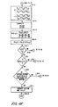
- Figure 4A shows, in flowchart form, the general method of passive ranging of the present invention.
- a single moving sensor 10 for example, mounted on an aircraft 32
- the baseline is the displacement of sensor 10 between the points A and B where each of two successive frames are taken.
- the first frame f(x,y) (image 99) is obtained (step 100) by the processor, the starting camera positions are initialized (step 102) and the next frame g(x,y) (image 100) is obtained for comparison.
- Frames f(x,y) and g(x,y) are then compared to derive a gross terrain correlation and then a fine terrain correlation, as described by the processing steps in blocks 300 and 302, respectively. If images f(x,y) and g(x,y) are closely spaced they will be easily registered. However, the stereo effect may not be strong enough to derive accurate range information.
- the gross terrain address modification coefficients derived in step.112 and the fine terrain (or altitude variation) address modification coefficients derived in step 118 may then be used as initial conditions when comparing frame f(x,y) with the next frame g(x,y), for example, a new image (not shown) taken from position C along flight path 30.
- a new image not shown
- This technique described above as "micro-stepping,” is continued until a b 3 eline is obtained from which accurate range information or a map, may be derived, as shown by steps 122 and 124.
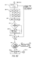
- Figures 4B, 4C, 4D and 4E show in greater detail the method of passive ranging of the present invention.
- the first digitized frame f(x,y) becomes available to the processor in step 100. Certain parameters are then initialized.
- the camera displacement vector (vi) relative to frame f(x,y) are set to zero in step 102-1.
- the direction cosine matrix of the camera rotation (li,j) relative to frame f(x,y) is set to the identity matrix (zero rotation) in step 102-2.
- the estimated tilt of the terrain relative to camera axes, or the scene plane normal (Lj) is initialized in step 102-3.
- the range R is set to the estimated altitude R o of the aircraft in step. 102-4.
- the threshold correlation number N (selected in accordance with the expected scene content) is set in step 102-5. For most scenes, correlation number N of 0.01 is sufficient.
- the r(x,y) array which is used to hold the altitude of every pixel (x,y) in frame f(x,y), is set to zero in steps 102-6, 102-7 and 102-8.
- the next digitized image g(x,y) is then obtained, as shown in step 104. This is the first image in the "micro-step" loop 304.
- the first and Nth frames (f(x,y) and g(x,y)) are then processed by taking each pixel (x,y) in turn.
- the address modification coefficients are calculated as a function of (x,y).
- step 106-2 computation of the distance (R(x,y)) along the vector direction (Lj) from the sensor to the pixel (x,y) as the sun of the median plane distance (R o ) and the local altitude variation (r(x,y)), is accomplished.
- step 110 The accuracy of this registration is assessed in step 110 where the image f(x,y) and the warped image g(X,Y) are correlated.
- the result (averaged over all pixels) will be dAi,j as shown in step 112-8.
- the steps 106 through 110 are repeated for all pixels in the frame by loop 306 connecting steps 106-6 and 106-1, as shown.
- step 110-1 the scene difference vector (V n ) is calculated as shown.
- steps 112-1 through 112-6 the incremental corrections ( ⁇ A i,j ) to the address modification coefficients (Ai,i) are calculated.
- steps 112-3 the starting values of the address modification coefficients (Ai,j) are calculated.
- the distinction between the local parameters (ai,j) and the global parameters (Ai,j) is that the local parameters are a function of (x,y) and the global parameters are not.
- the global parameters are an approximation for the purpose of computing an update to the camera displacement parameters (vi) and (l i,j ).
- the global parameters (A i,j ) are computed from the current values of (v i /R o ) and (l i,j ), as shown in step 112-3.
- Step 112-4 calculates a one-dimensional integer subscript (k) equivalent to the two-dimensional subscript (i,j) of the address modification coefficients. That is, when (i,j) equals (1,1), (1,2), (1,3), (2,1) ... (3,2), k will equal 1, 2, 3, 4 ... 8.
- step 112-5 through 112-7 the incremental corrections ( ⁇ A i,j ) to the address modification coefficients (Ai,j) are calculated by matrix multiplication of the scene difference vector V n by the 8x8 inverse matrix [M n,k ] -1 . This M n,k matrix is calculated as described above.
- step 112-8 a new set of address modification coefficients, Ai,j( new ), is calculated by applying the corrections ( ⁇ A i,j ) to the starting values of A i,j .
- Step 112-2 checks to determine whether the last values of i and j are to be used for the address modification calculations in steps 112-3 through 112-8. Since the scene geometry always defines the A 3,3 value to be one, if the values of i and j are both three (3), processing will continue, through step 112-9 to step 112-10. If all values of i and j have not been processed, processing returns via loop 305 to step 112-1. Otherwise, the updated values of Ai,j are then used to compute updated values of the displacement parameters vi, l i,j and L j as shown in step 114.
- step 118 If the change dAi,j in Ai,j that has just been computed is smaller than N, the gross terrain correction is not likely to be significantly improved. The process then moves to step 118. If not, it jumps back to step 106-1 via loop 306 and executes another pass over the image f(x,y).
- step 118-1 a processing loop is initiated over all pixels in the image f(x,y) in order to register the fine terrain structure of the two images f(x,y) and g(x,y).
- the modified address (X,Y) is then computed in steps 118-2 and 118-3 in the same manner as in step 106.
- the value of (X,Y) is a function of range (R), as shown in step 118-2.
- step 118-4 the values of dX/dR, dY/dR are computed for each pixel (x,y).
- step 118-5 a correction (dr(x,y)) to the local altitude variation (r(x,y)) is computed.
- Step 118-6 is used to update the altitude variation function (r(x,y)). If all pixels (x,y) have not been processed, the process continues via loop 308 to step 118-1.
- step 120 the current change (dr(x,y)) in r(x,y) is analyzed in step 120 to determine if the value cf r(x,y) has reached its limiting value so that no further change is likely to occur. If further change is possible, the process jumps back to step 106-1 via loop 310 and the processing over all pixels is repeated for fine terrain registration.
- the device and method of the present invention uses a "range slicing" technique in order to ascertain the distance between camera 10 and detail in the scene of interest, thereby creating a range map of the scene.
- the following information is known: the direction cosines vector (Lj) of the scene plane normal, the distance between the camera and the average scene plane (range "R"), the camera rotation matrix (l i,j ), and the camera translation vector (vi).
- the position of each scene detail pixel (X,Y) of the new image may be related to a given pixel (x,y) of the reference image, by the following address transformations: where the coefficients ai,j of the transformation equations are calculated as follows:
- the camera rotation matrix (li,j) and camera translation matrix (vi) will be known, for example, by position and motion sensors 19 also attached to the platform carrying the present invention.
- the values of the direction cosine matrix (Lj) and range (R) are estimated, either using the last calculated values, or the nominal values of zero (0), zero (0), and one (1) for Li, L 2 and L 3 , respectively, and the aircraft 32 altitude (taken from altitude sensor 21) for R.
- the reference image is then warped using Equations (23) and (24), and the address modification coefficients are calculated using Equation (25). This warped image is then compared to the second image 100 by some correlation technique, for example, by subtraction.
- the ai,j coefficients are calculated, and the transformation and correlation are performed. For each "slice”, those pixels which correlate lie on the slice. The portions of the scene lying in each plane are thus determined.
- the accumulated information relating portions of the image with each range slice are an approximation to the continuous height distribution function with an accuracy of half the plane separation, i.e., a range-based topographic map.
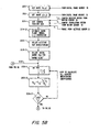
- FIG. 5A shows a flowchart of the general method of passive ranging in this alternate embodiment.
- Figures 5B and 5C show the method in greater detail.
- the two stereo images f(x,y) and g(x,y) are obtained from digital image memories 14 and 16 in steps 200 and 202, respectively.
- Camera position data is obtained from altitude sensor 21 and motion sensor 19 in step 204. This includes the camera rotation matrix li,j, camera translation vector vi and range R.
- step 204-2 the orientation of the scene plane normal Lj is also estimated.
- an altitude resolution dr is selected in step 206-1.
- An initial range R o is selected for the "range slice," as shown in step 206-2.
- Steps 208, 210 and 212 comprise the method steps of computing the appropriate address modification coefficients for the range slice, warping image g(x,y) with the new address modification and comparing f(x,y) with the warped image g(X,Y), respectively.
- step 210 further comprises the steps of, for each pixel (x,y), calculating the address modification (X,Y) in step 210-2, and calculating the difference between f(x,y) and g(X,Y) in step 212.
- step 214 Based on the comparison in step 214, the address (x,y) of all pixels in the two images that match are extracted and assigned a range value of R o . In other words, those pixel locations having matching intensities are defined to lie on the range slice at a distance R o from camera 10. As shown in Figure 5C, this process includes the steps of evaluating the difference in step 214-1 and then assigning the distance of the range slice R o to the range map function R(x,y) in step 214-2.
- step 216 it is determined whether all range "slices" have been examined. If they have not, a new value of R o is selected in step 217, and processing returns to step 208 via loop 400. Otherwise, the altitude map R(x,y) is generated in step 218-1.
Landscapes
- Engineering & Computer Science (AREA)
- Radar, Positioning & Navigation (AREA)
- Remote Sensing (AREA)
- Physics & Mathematics (AREA)
- General Physics & Mathematics (AREA)
- Multimedia (AREA)
- Automation & Control Theory (AREA)
- Image Analysis (AREA)
- Measurement Of Optical Distance (AREA)
- Length Measuring Devices By Optical Means (AREA)
Applications Claiming Priority (2)
| Application Number | Priority Date | Filing Date | Title |
|---|---|---|---|
| US06/597,629 US4635203A (en) | 1984-04-06 | 1984-04-06 | Passive range measurement apparatus and method |
| US597629 | 1984-04-06 |
Publications (2)
| Publication Number | Publication Date |
|---|---|
| EP0157414A2 true EP0157414A2 (de) | 1985-10-09 |
| EP0157414A3 EP0157414A3 (de) | 1988-08-24 |
Family
ID=24392297
Family Applications (1)
| Application Number | Title | Priority Date | Filing Date |
|---|---|---|---|
| EP85103990A Withdrawn EP0157414A3 (de) | 1984-04-06 | 1985-04-02 | Verfahren und Vorrichtung zur Distanzmessung |
Country Status (3)
| Country | Link |
|---|---|
| US (1) | US4635203A (de) |
| EP (1) | EP0157414A3 (de) |
| IL (1) | IL74714A (de) |
Cited By (8)
| Publication number | Priority date | Publication date | Assignee | Title |
|---|---|---|---|---|
| EP0282966A3 (de) * | 1987-03-20 | 1990-01-31 | Honeywell Inc. | Methode und Vorrichtung für dreidimensionale Abbildung |
| DE4216828A1 (de) * | 1992-05-21 | 1993-12-02 | Dornier Gmbh | Verfahren zur Erdbeobachtung |
| GB2289389A (en) * | 1994-05-11 | 1995-11-15 | Bodenseewerk Geraetetech | Misile location |
| DE4419359A1 (de) * | 1994-06-03 | 1995-12-07 | Wolfram Dipl Ing Kirchner | Verfahren zur Erfassung, Auswertung, Ausmessung und Speicherung von Geo-Informationen |
| DE3708683C2 (de) * | 1986-03-17 | 2000-04-06 | Geospectra Corp | Verfahren zur Bestimmung von Lageänderungen einer bewegten Bildsensorplattform |
| RU2244260C1 (ru) * | 2003-04-09 | 2005-01-10 | Анцыгин Александр Витальевич | Способ получения и актуализации цифрового картографического материала и устройство для его осуществления |
| RU2246695C2 (ru) * | 2002-12-20 | 2005-02-20 | 29 Нии Мо Рф | Способ актуализации цифровой карты местности и устройство для его осуществления |
| CN111006599A (zh) * | 2019-10-30 | 2020-04-14 | 东北大学 | 基于像素光栅和计算机视觉的物体表面微尺度测量方法 |
Families Citing this family (31)
| Publication number | Priority date | Publication date | Assignee | Title |
|---|---|---|---|---|
| US4695959A (en) * | 1984-04-06 | 1987-09-22 | Honeywell Inc. | Passive range measurement apparatus and method |
| US4828382A (en) * | 1986-04-18 | 1989-05-09 | Sundstrand Data Control, Inc. | Passive radio altimeter |
| US4866626A (en) * | 1987-09-18 | 1989-09-12 | Egli Werner H | Navigation by a video-camera sensed ground array |
| US4891762A (en) * | 1988-02-09 | 1990-01-02 | Chotiros Nicholas P | Method and apparatus for tracking, mapping and recognition of spatial patterns |
| US4916536A (en) * | 1988-11-07 | 1990-04-10 | Flir Systems, Inc. | Imaging range finder and method |
| US4969735A (en) * | 1989-03-07 | 1990-11-13 | Sperry Marine Inc. | Passive range finding apparatus utilizing television sensors |
| US5990822A (en) * | 1989-04-14 | 1999-11-23 | Honigsbaum; Richard F. | Process and apparatus for finding stealthcraft |
| US5090797A (en) * | 1989-06-09 | 1992-02-25 | Lc Technologies Inc. | Method and apparatus for mirror control |
| US5231674A (en) * | 1989-06-09 | 1993-07-27 | Lc Technologies, Inc. | Eye tracking method and apparatus |
| US4974010A (en) * | 1989-06-09 | 1990-11-27 | Lc Technologies, Inc. | Focus control system |
| US5144373A (en) * | 1989-08-02 | 1992-09-01 | Loral Aerospace Corp. | Detection of range discontinuities in stereoscopic imagery |
| US5128874A (en) * | 1990-01-02 | 1992-07-07 | Honeywell Inc. | Inertial navigation sensor integrated obstacle detection system |
| US5166681A (en) * | 1990-07-30 | 1992-11-24 | Bottesch H Werner | Passive vehicle presence detection system |
| JPH04120413A (ja) * | 1990-09-10 | 1992-04-21 | Mitsubishi Electric Corp | 車間距離計における追尾装置 |
| US5259037A (en) * | 1991-02-07 | 1993-11-02 | Hughes Training, Inc. | Automated video imagery database generation using photogrammetry |
| US5764770A (en) * | 1995-11-07 | 1998-06-09 | Trimble Navigation Limited | Image authentication patterning |
| US5799082A (en) * | 1995-11-07 | 1998-08-25 | Trimble Navigation Limited | Secure authentication of images |
| US6282362B1 (en) | 1995-11-07 | 2001-08-28 | Trimble Navigation Limited | Geographical position/image digital recording and display system |
| US6118401A (en) * | 1996-07-01 | 2000-09-12 | Sun Microsystems, Inc. | Aircraft ground collision avoidance system and method |
| US5831621A (en) * | 1996-10-21 | 1998-11-03 | The Trustees Of The University Of Pennyslvania | Positional space solution to the next best view problem |
| FR2758888B1 (fr) * | 1997-01-27 | 1999-04-23 | Thomson Csf | Procede de modelisation fine du fouillis de sol recu par un radar |
| US7447380B2 (en) * | 2002-09-12 | 2008-11-04 | Inoe Technologies, Llc | Efficient method for creating a viewpoint from plurality of images |
| US7095488B2 (en) * | 2003-01-21 | 2006-08-22 | Rosemount Aerospace Inc. | System for profiling objects on terrain forward and below an aircraft utilizing a cross-track laser altimeter |
| FR2897163B1 (fr) * | 2006-02-08 | 2008-04-11 | Thales Sa | Procede de geo-localisation d'une ou plusieurs cibles |
| US7834910B2 (en) * | 2006-03-01 | 2010-11-16 | David M. DeLorme | Method and apparatus for panoramic imaging |
| US7924316B2 (en) * | 2007-03-14 | 2011-04-12 | Aptina Imaging Corporation | Image feature identification and motion compensation apparatus, systems, and methods |
| US7920746B2 (en) * | 2007-04-23 | 2011-04-05 | Aptina Imaging Corporation | Compressed domain image summation apparatus, systems, and methods |
| US8264377B2 (en) | 2009-03-02 | 2012-09-11 | Griffith Gregory M | Aircraft collision avoidance system |
| US20160349746A1 (en) * | 2015-05-29 | 2016-12-01 | Faro Technologies, Inc. | Unmanned aerial vehicle having a projector and being tracked by a laser tracker |
| CA3005894A1 (en) | 2015-11-20 | 2017-05-26 | Magic Leap, Inc. | Methods and systems for large-scale determination of rgbd camera poses |
| US11682313B2 (en) | 2021-03-17 | 2023-06-20 | Gregory M. Griffith | Sensor assembly for use in association with aircraft collision avoidance system and method of using the same |
Family Cites Families (7)
| Publication number | Priority date | Publication date | Assignee | Title |
|---|---|---|---|---|
| US4359732A (en) * | 1963-11-21 | 1982-11-16 | Goodyear Aerospace Corporation | Topographical mapping radar |
| US3546375A (en) * | 1965-09-20 | 1970-12-08 | Hughes Aircraft Co | Three-dimensional terrain mapping system |
| US3905045A (en) * | 1973-06-29 | 1975-09-09 | Control Data Corp | Apparatus for image processing |
| US3961851A (en) * | 1974-10-03 | 1976-06-08 | The United States Of America As Represented By The Secretary Of The Army | Passive stereovision range finder |
| US4032912A (en) * | 1974-10-03 | 1977-06-28 | General Electric Company | Intensity modulated display system |
| US4122521A (en) * | 1975-10-20 | 1978-10-24 | Northrop Corporation | Correlation system for multiple-sensor reconnaissance vehicle |
| US4504915A (en) * | 1982-06-30 | 1985-03-12 | Pitney Bowes Inc. | Method and apparatus for individualized postage value computing |
-
1984
- 1984-04-06 US US06/597,629 patent/US4635203A/en not_active Expired - Fee Related
-
1985
- 1985-03-25 IL IL74714A patent/IL74714A/xx unknown
- 1985-04-02 EP EP85103990A patent/EP0157414A3/de not_active Withdrawn
Cited By (12)
| Publication number | Priority date | Publication date | Assignee | Title |
|---|---|---|---|---|
| DE3708683C2 (de) * | 1986-03-17 | 2000-04-06 | Geospectra Corp | Verfahren zur Bestimmung von Lageänderungen einer bewegten Bildsensorplattform |
| EP0282966A3 (de) * | 1987-03-20 | 1990-01-31 | Honeywell Inc. | Methode und Vorrichtung für dreidimensionale Abbildung |
| DE4216828A1 (de) * | 1992-05-21 | 1993-12-02 | Dornier Gmbh | Verfahren zur Erdbeobachtung |
| US5883584A (en) * | 1992-05-21 | 1999-03-16 | Dornier Gmbh | Earth observation method |
| GB2289389A (en) * | 1994-05-11 | 1995-11-15 | Bodenseewerk Geraetetech | Misile location |
| FR2719920A1 (fr) * | 1994-05-11 | 1995-11-17 | Bodenseewerk Geraetetech | Procédé et dispositif destinés à soutenir la navigation inertielle d'un missile se dirigeant de façon autonome sur une cible éloignée. |
| GB2289389B (en) * | 1994-05-11 | 1998-06-24 | Bodenseewerk Geraetetech | Method and device of updating the inertial navigation of a missile autonomously heading for a remote target |
| DE4419359A1 (de) * | 1994-06-03 | 1995-12-07 | Wolfram Dipl Ing Kirchner | Verfahren zur Erfassung, Auswertung, Ausmessung und Speicherung von Geo-Informationen |
| RU2246695C2 (ru) * | 2002-12-20 | 2005-02-20 | 29 Нии Мо Рф | Способ актуализации цифровой карты местности и устройство для его осуществления |
| RU2244260C1 (ru) * | 2003-04-09 | 2005-01-10 | Анцыгин Александр Витальевич | Способ получения и актуализации цифрового картографического материала и устройство для его осуществления |
| CN111006599A (zh) * | 2019-10-30 | 2020-04-14 | 东北大学 | 基于像素光栅和计算机视觉的物体表面微尺度测量方法 |
| CN111006599B (zh) * | 2019-10-30 | 2021-07-20 | 东北大学 | 基于像素光栅和计算机视觉的物体表面微尺度测量方法 |
Also Published As
| Publication number | Publication date |
|---|---|
| EP0157414A3 (de) | 1988-08-24 |
| IL74714A (en) | 1988-11-15 |
| US4635203A (en) | 1987-01-06 |
Similar Documents
| Publication | Publication Date | Title |
|---|---|---|
| US4635203A (en) | Passive range measurement apparatus and method | |
| US4695959A (en) | Passive range measurement apparatus and method | |
| EP3333538B1 (de) | Vis-scanner | |
| US7773799B2 (en) | Method for automatic stereo measurement of a point of interest in a scene | |
| US10699430B2 (en) | Depth estimation apparatus, autonomous vehicle using the same, and depth estimation method thereof | |
| US9322646B2 (en) | Adaptive mechanism control and scanner positioning for improved three-dimensional laser scanning | |
| US5577130A (en) | Method and apparatus for determining the distance between an image and an object | |
| US5422828A (en) | Method and system for image-sequence-based target tracking and range estimation | |
| JP3880702B2 (ja) | 画像のオプティカルフロー検出装置及び移動体の自己位置認識システム | |
| US9857232B2 (en) | Device for non-contact temperature measurement and temperature measurement method | |
| Rumpler et al. | Evaluations on multi-scale camera networks for precise and geo-accurate reconstructions from aerial and terrestrial images with user guidance | |
| US20060215935A1 (en) | System and architecture for automatic image registration | |
| US6175648B1 (en) | Process for producing cartographic data by stereo vision | |
| GB2289389A (en) | Misile location | |
| US20030118213A1 (en) | Height measurement apparatus | |
| Sheikh et al. | Geodetic alignment of aerial video frames | |
| US12072420B2 (en) | Methods and apparatus for geospatial data generation | |
| JPH10153426A (ja) | 地形測定装置 | |
| Short | 3-D Point Cloud Generation from Rigid and Flexible Stereo Vision Systems | |
| US3548210A (en) | Automatic stereoplotter | |
| CN120445184B (zh) | 利用水面平台相机模组进行无人机定位的装置及方法 | |
| Filippov et al. | Long-Range Thermal 3D Perception in Low Contrast Environments | |
| JP2000331145A (ja) | 三次元対象体画像解析方法及びその関連技術 | |
| Lang et al. | 3d scene reconstruction from ir image sequences for image-based navigation update and target detection of an autonomous airborne system | |
| Rodrigo | Indoor Feature Tracking |
Legal Events
| Date | Code | Title | Description |
|---|---|---|---|
| PUAI | Public reference made under article 153(3) epc to a published international application that has entered the european phase |
Free format text: ORIGINAL CODE: 0009012 |
|
| AK | Designated contracting states |
Designated state(s): DE FR GB IT |
|
| PUAL | Search report despatched |
Free format text: ORIGINAL CODE: 0009013 |
|
| AK | Designated contracting states |
Kind code of ref document: A3 Designated state(s): DE FR GB IT |
|
| 17P | Request for examination filed |
Effective date: 19890124 |
|
| 17Q | First examination report despatched |
Effective date: 19900514 |
|
| STAA | Information on the status of an ep patent application or granted ep patent |
Free format text: STATUS: THE APPLICATION HAS BEEN WITHDRAWN |
|
| 18W | Application withdrawn |
Withdrawal date: 19900802 |
|
| R18W | Application withdrawn (corrected) |
Effective date: 19900802 |
|
| RIN1 | Information on inventor provided before grant (corrected) |
Inventor name: MERCHANT, JOHN |