EP0157468A2 - Munition à gaz comprimé pour armes portatives - Google Patents
Munition à gaz comprimé pour armes portatives Download PDFInfo
- Publication number
- EP0157468A2 EP0157468A2 EP85300338A EP85300338A EP0157468A2 EP 0157468 A2 EP0157468 A2 EP 0157468A2 EP 85300338 A EP85300338 A EP 85300338A EP 85300338 A EP85300338 A EP 85300338A EP 0157468 A2 EP0157468 A2 EP 0157468A2
- Authority
- EP
- European Patent Office
- Prior art keywords
- piston
- cartridge
- base end
- casing
- rearwards
- Prior art date
- Legal status (The legal status is an assumption and is not a legal conclusion. Google has not performed a legal analysis and makes no representation as to the accuracy of the status listed.)
- Withdrawn
Links
Images


Classifications
-
- F—MECHANICAL ENGINEERING; LIGHTING; HEATING; WEAPONS; BLASTING
- F41—WEAPONS
- F41B—WEAPONS FOR PROJECTING MISSILES WITHOUT USE OF EXPLOSIVE OR COMBUSTIBLE PROPELLANT CHARGE; WEAPONS NOT OTHERWISE PROVIDED FOR
- F41B11/00—Compressed-gas guns, e.g. air guns; Steam guns
- F41B11/60—Compressed-gas guns, e.g. air guns; Steam guns characterised by the supply of compressed gas
- F41B11/62—Compressed-gas guns, e.g. air guns; Steam guns characterised by the supply of compressed gas with pressure supplied by a gas cartridge
-
- F—MECHANICAL ENGINEERING; LIGHTING; HEATING; WEAPONS; BLASTING
- F41—WEAPONS
- F41B—WEAPONS FOR PROJECTING MISSILES WITHOUT USE OF EXPLOSIVE OR COMBUSTIBLE PROPELLANT CHARGE; WEAPONS NOT OTHERWISE PROVIDED FOR
- F41B11/00—Compressed-gas guns, e.g. air guns; Steam guns
- F41B11/70—Details not provided for in F41B11/50 or F41B11/60
- F41B11/72—Valves; Arrangement of valves
- F41B11/723—Valves; Arrangement of valves for controlling gas pressure for firing the projectile only
-
- F—MECHANICAL ENGINEERING; LIGHTING; HEATING; WEAPONS; BLASTING
- F42—AMMUNITION; BLASTING
- F42B—EXPLOSIVE CHARGES, e.g. FOR BLASTING, FIREWORKS, AMMUNITION
- F42B6/00—Projectiles or missiles specially adapted for projection without use of explosive or combustible propellant charge, e.g. for blow guns, bows or crossbows, hand-held spring or air guns
- F42B6/10—Air gun pellets ; Ammunition for air guns, e.g. propellant-gas containers
Definitions
- This invention concerns cartridge ammunition for small arms, such as pistols rifles and automatic small arms, which ammunition is adapted to utilise air or another gas at high pressures to propel missiles, in which the cartridge is of a kind comprising a casing, a gas storage chamber in the casing, a piston reciprocable in a cylinder in the casing, discharge valve means controlling a discharge passage from the chamber to a front discharge end of the casing, and actuating means including rear or base end in a rear base end portion of the casing which rear part is actuable to allow the piston to be moved rearwards in said cylinder by gas pressure in said storage chamber, and including an elongate part extending within said storage chamber to connect said piston and valve means for opening the valve means when the piston moves rearwards.
- an ammunition cartridge for a round of ammunition comprising a casing, a gas storage chamber in the casing, a piston reciprocable in a cylinder in the casing, discharge valve means controlling a discharge passage from the chamber to a front discharge end of the casing, and actuating means including rear or base end part in a rear base end portion of the casing which rear part is actuable to allow the piston to be moved rearwards in said cylinder by gas pressure in said storage chamber, and including an elongate part extending within said storage chamber to connect said piston and valve means for opening the valve means when the piston moves rearwards, and characterised in that:-
- the shock attenuator or absorber means preferably comprises a resilient insert disposed so as to be compressed by the piston as the latter moves rearwards.
- shock attenuator or absorber means and the piston are preferably arrangd so that the latter can move rearwards through a predetermined distance prior to compressing the resilient insert.
- the resilient insert is preferably in the form of a mass-produced elastomeric body, such as an "O"-ring, which is preferably made from nitrile rubber, neoprene, or other elastomer having good shear resistance and shape-memory so as to resist permenant distortion.
- the insert may be a metallic spring or may be of composite metal and elastomer construction.
- the actuating means preferably comprises static or reactive thrust means movable radially inwards from a position in which it blocks rearward movement of the piston to a position in which the piston can move rearwards.
- Said static or reactive thrust means preferably comprises at least one rigid member disposed in said rear base end porton and a displacer which incorporates or constitutes said base end or rear part of the actuating means, the displacer being actuable to allow or cause the rigid member or members to move transversely relative to the piston.
- Displacer bias means is preferably provided to restore the displacer automatically to an un-actuated position.
- the piston is preferably hollow and contains and bias means.
- An extension of the piston preferably serves as the movable member of the actuating means, and the discharge valve means is preferably mounted on said extension so that at least part of the discharge valve means is permitted to move through a limited distance in a predetermined direction from a normal position relative to said extension, to facilitate charging of the cartridge with compressed gas.
- the discharge valve means is preferably of poppet valve form for closing said discharge opening.
- the effective area of the valve means is preferably no more than about half the working area of the piston. Said effective area may be as little as one tenth of said working area, but is preferably between one third and one fifth of the working area to enable the discharge opening to be made sufficiently large to permit the compressed gas to be discharged rapidly.
- the piston is preferably arranged to accelerate through a predetermined distance before opening the discharge valve means, so that the opening of the latter is rapid and sudden, and said distance is preferably minimal to minimise the delay between actuation and opening of the discharge valve means.
- the invention includes a round of ammunition comprising a cartridge of the invention, a missile and retaining means to releasably retain and connect the missile to the cartridge.
- the rounds of ammunition generally comprise a missile 10, retaining means 11 for holding the missile, and a cartridge 12; and the cartridge 12 is an assembly comprising a hollow casing 13 within an intermediate portion of which is a gas storage space 18 disposed between a hollow discharge (front) end portion 14 and a base (rear) end portion 20 of the casing, discharge valve means 30 and actuating means 60.
- the actuating means generally comprises servo-piston means 61, servo actuating means 62 and discharge valve actuating means 63 arranged so that the means 62 is responsive to being struck by a firing pin 43 of a gun to allow the piston means 61 to utilise energy from compressed gas stored in the space 18 for forcing the discharge valve actuating means to open the discharge valve means 30 to permit said gas to leave said space and expel the missile 10 from the retaining means.
- the cartridge is provided with shock attentuator or absorber means which is shown in all embodiments as comprising a resilient insert 400 in the form of an "O" ring, and the servo-piston means 61 has a rearwardly directed surface 401 which abuts and compresses the insert when the piston moves.
- the servo-piston means 61 is inside the compressed gas storage space 18, and both sides of the piston means 61 are normally subjected to the pressure of the stored gas.
- the servo actuating means 62 is in the form of closure means for opening of a servo-passage to subject the rear side of the piston means to a lower, e.g. atmospheric pressure, by venting of the gas behind the piston means, to subject the piston means to said pressure differential thereby causing the piston means to move rearwards for opening the discharge valve means 30.
- the missile 10 and the returning means in the form of a snap-on nosepiece, are shown in broken outline in FIGURE 1.
- the discharge end portion 14 of the casing 13 is of simple one piece form, and the base end portion 20 is internally grooved.
- An insert member 215 is retained in the base end portion by a circlip 200 engaged in the groove in said portion 20.
- the portion 14 defines a first wall 216, and the member 215 defines a second wall 217 confronting the first wall whereby to define, within the casing, the gas storage space 18 which in this embodiment extends rearwards beyond the intermediate portion of the casing and into the base end portion 20.
- the insert member 215 serves as a partition between the space 18 and the open end of the portion 20, and defines a servo passage 228 which extends through the second wall.
- the piston means 61 comprises a piston 221 slidably located in the space 18 adjacent the second wall 217 to divide the space into a main storage portion 218 in front of the piston, and a servo cylinder portion 219 in which the piston can move.
- the actuating means 60 in the first embodiment shown in FIGURES 1 and 2, further comprises a movable member 225 having a hollow rear portion 226 (integral with the piston 221) and a front portion 227.
- a bush 201 is slidably accommodated (as a clearance fit) in the portion 226, and a servo valve spring 242 is trapped in the portion 226 between the bush 201 and the front portion 227.
- a restricted charging passage 202 is provided in the portion 226 t to allow gas to pass from the main storage portion 218 through the portion 2326 along the outside of the bush 201 to the servo cylinder 219.
- the closure means is in the form of servo valve means 238, which comprises a valve member 241 which extends through the passage 228 into the bush 201.
- the spring 242 urges a sealing part 240 of the valve member 241 into engagement with a seating 204 (FIGURE 2) on the insert member 215 to close the passage 228.
- a base end part 244 of the member 241 is disposed in the base-end portion 20 so as to be exposed.
- the spring 242 also serves as a sealing bias spring to urge the portion 227 towards the first wall 216 for closing the discharge valve means 30.
- the discharge valve means 30 comprises an "O" ring seal 233 and an end part 234 of the front part 227, which part 234 is a clearance fit in a discharge passage 231.
- the insert member 215 locates the insert 400 alongside a sealing ring 402, both of which are compressed by the piston 221 as shown in FIGURE 2.
- a single large ring may be used as a seal and insert, or the sealing ring 402 may be employed as the shock absorber, the piston being modified to abut the ring 402 or to abut a hard plastics or metal short cylindrical thrust member inserted in place of the ring 400.
- the movable member 225A is solid except for a recess 205 for the sealing bias spring 236A for closing the discharge valve means 30, and for a restricted charging passage 202; and the closure means comprises solely a rear end part 251 is in the form of an exposed frangible web integral with a screwed in insert member 215A so as to close the servo passage 228A, which member 215A has an "O" ring peripheral seal.
- the unshown remainder of the cartridge is the same as shown in FIGURE 1.
- the insert 400 is partially accommodated in a recess 403 in the insert member 215A.
- the recess 403 is dimensioned so that the maximum compression of the insert is limited by the surface 401 abutting the member 215A.
- the insert may be in the form of an annular or short cylindrical body affixed to the insert member 215A or secured partially in the recess 403, so as to be replaceable with the insert member 215A after firing.
- the servo piston means 62 in the charged condition of the cartridge, is subjected to two balanced opposing thrusts both deriving from the stored gas pressure; and the servo-actuating means 62 is operable, in use, to cause a change in the pressure acting on one side of the piston to unbalance the two opposing thrusts.
- this embodiment requires the servo-actuating means 62 to incorporate closure means, a barrier or partition and a servo passage which collectively serve as means for controlling gas flow.
- the servo actuating means 62 is in the form of static or reactive thrust means of a mechanical form which, in the non-actuated state of the servo mechanism, provides a static thrust to the piston in reaction to the thrust provided by the stored gas pressure, and thus obviates the need for such means for controlling gas flow; and with the exception of certain seals, e.g. "0" rings, the cartridges are all of metal construction.
- the second embodiment of the round of ammunition comprises the missile 10, the nosepiece 11 and the cartridge 12.
- the latter is an assembly in which the discharge end portion 14 is integral with the casing 13, and the assembly includes an internal member 315 which is held by a circlip in the base end portion 20 of the casing.
- the member 315 has a central aperture 323.
- the base end portion 20 provides a servo cylinder 319 at one end of a gas storage space 18 for the servo-piston means 61 which comprises a piston 321.
- the space 18 extends from the piston and through the intermediate portion of the casing to a first wall 316 defined by the discharge end portion 14.
- Discharge valve means 335 is provided to close a discharge aperture in the first wall at the rear end of a discharge passage 331.
- the discharge valve means 30 comprises a bias spring 336 which acts on a backing washer 332 to compress an elastomeric secondary sealing ring 333 against a valve member 334 which abuts a head 335 at the end of a movable member 324.
- the valve member 334 has a 45° conically tapered seating face which sealingly engges the similarly tapered wall 316 around the discharge aperture, and the rings 333 engages the wall at the junction between the periphery of the valve member and the wall to seal said junction against ingress of gas stored at very high pressures.
- the discharge valve actuating means 63 comprises the movable member 324, extending within the space 18 from the piston to the valve means 331; and the servo actuating means 62 comprises static thrust means 300 disposed in the base end portion 14.
- the static thrust means comprises a pair of rigid members 301 and a displacer 302 disposed between said members 301.
- the displacer (FIGURE 5) has a waist 303 between a head 304 and a base end part 305 exposed centrally at the base end of the cartridge casing 13.
- the static thrust means 300 is in a blocking condition in which the rigid members 301 abut a tapered part conical abutment surface 306 of the piston and are supported against movement towards the axis of the piston by engagement with the peripheral surface 307 of the head 304.
- the piston is urged rearwards towards the base of the cartridge by a major thrust of the pressure of the gas stored in the space 18 and the much smaller thrust of the spring 336; and these thrusts are opposed by the static resistive or reactive thrust exerted by the rigid members 301 on the piston, together with the thrust of the lower pressure, e.g. atmospheric pressure, existing in the cylinder to the rear of the piston, and the thrust of a displacer resetting spring 308 acting between the piston and the static thrust means, so that the piston is held in an un-actuated state and the discharge valve means remains closed.
- the lower pressure e.g. atmospheric pressure
- the base end part 305 is exposed at the base so that, when the round is in the breech of a gun, the part 305 can be struck and moved forwards (towards the nose) by a firing pin of a gun.
- the head 304 is moved forwards from between the rigid members 301, the inclination of the surface 306 causes the rigid members to move radially inwards into the waist 303.
- the dimensions of the rigid members and waist are such that they can be accepted in a recess 309 in the rear of the piston thereby allowing the piston to move rearwards to an actuated position in which it abuts to the internal member 315 as shown in FIGURE 13.
- the resetting spring 308 is stronger than the valve bias spring 336 so that, when the pressure in the space 18 drops to near atmospheric pressure, the spring 308 automatically restores the piston to the un-actuated position closing the valve means, and also thrusts the displacer rearwards so that a part conical surface 311 between the head and the waist thrusts the rigid members radially outwards to the blocking position so that the cartridge is restored to the mechanical condition shown in FIGURE 12.
- a washer 310 ensures that the rigid members 301 are ejected from the recess 309.
- the insert 400 is merely shown diagrammatically inserted into the space between the insert member 315 and the surface 401.
- the insert 400A could be employed so as to be compressed between the surface 401A and the washer 310 on the displacer 302, if the recess 309 is longitudinally enlarged to limit compression of the insert 400A; or a thicker form of the washer 310, e.g. of steel backed hard resilient plastics could be employed as the shock absorber in place of the washer 310 and "O" ring 400A.
- the cartridge can be recharged by pumping compressed gas into the discharge passage thereby causing the valve parts 332, 333 and 334 to move rearwards along the movable member 324 so opening the valve means against the bias of the spring 336.
- the discharge valve means thus serves as automatic non-return valve means during charging of the cartridge.
- the static thrust means may be of any suitable form.
- simpler part cylindrical rigid members may be employed instead of the rigid members shaped as shown in FIGURES 4 to 6.
- a single rigid member may be used in combination with means, such as a spring or an eccentric formation of part of the displacer, to hold the rigid member in an eccentric blocking position, the displacer being shaped and movable to move the rigid member to a position concentric or aligned with the recess 309 to actuate the piston.
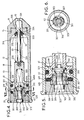
- the modified form of the second embodiment is similar to the second embodiment, but the modified form incorporates several improvements in its detail construction and arrangement, and is intended as a substitute for a .38 special firearms cartridge, for use in a firearm provided with a barrel liner.
- the static thrust means 300 employs several rigid members in the form of six ball bearings balls 301A, each ball having a diameter of 2mm.
- the displacer 302A is a one piece hardened steel part which is machined to provide the peripheral cylindrical surface 307, and the part conical surface 311 on a modified head 304A which integrally incorporates a flange 310A instead of the washer 310 shown in FIGURE 10.
- a further part conical surface 312 is provided between the shortened waist 303A and the base end part 305A.
- This form of the static thrust means is less expensive, is easier to assemble and is more reliable in operation than the form shown in FIGURES 4 and 5.
- the recess 309 is relatively large and is defined in a piston skirt 321B.
- the base end part of the skirt is internally chamfered to provide the part conical abutment surface 306A (FIGURE 8).
- the "0" ring 400 is disposed within the recess 309A, as shown in FIGURES 7 and 8. After actuation, the ring 400 is compressed in the recess 309A between the head 304A and the surface 401 until the skirt 321B strikes the end member 315A.
- the movable member 324A is integral with the piston and accommodates part of the displacer resetting spring 308, and a front end portion 324B is shaped to form part of the discharge valve means 30, and serves to carry and locate two resilient "O" rings 333A and 333B between a backing flange 332B and a head 335A.
- the first "O" ring 333A serves as a seal
- the rear “0" ring 333B serves as a spring in place of the spring 336 shown in FIGURE 4.
- the head 335A is dimensioned so as to be a clearance fit in the discharge passage 331.
- the internal member 315A is screwed into the base end portion 20 of the casing, and integrally incorporates a base end flange of the cartridge.
- This modified form of cartridge is suitable for use with stored gas pressures of about 300 kilogrammes per square centimetre or more, and has a preferred working pressure range of between 200 and 300 kilogrammes per square centimetre, whereas some of the embodiments described hereinbefore are designed to work at lower pressures of, for example, 100 to 200 kilogrammes per square centimetre.
- this modified form shown in FIGURES 7 to 9 is designed to improve the rate of discharge of the stored gas, and to operate reliably for a large number of charging and discharging cycles.
- the head 335A is shaped and positioned so that it is accommodatd in one end of the discharge passage so as to substantially block the discharge aperture 329 (FIGURE 8) when the valve is closed.
- the first "O" ring 333A overlies the junction, and seals the junction, between the head and the discharge aperture whilst the valve is closed to prevent escape of gas.
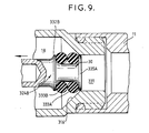
- the initial rearwards movement of the piston will bring the head 335A to the transient position shown in FIGURE 9, and in this position the head has moved nearly, but not completely, out of the discharge passage 331 and discharge opening 329, and has lifted the first "O" ring 333A off the wall 316 so that there is a clear space between the "O" ring 333A and the wall 316 whilst flow from the space 18 is obstructed by the head.
- the piston will have accelerated so that the head 335A passes through the transient position very rapidly to reach the fully open position shown in FIGURE 8 in a fraction of a second after passing through the transient position.
- the spring 308A restores the piston 321A to the position shown in FIGURE 15, and the part conical surface 311 causes the balls 301A to move radially outwards to the position shown in FIGURE 15 also.
- the second embodiment and the modified form have the major advantage that if the round is overheated, e.g. by a fire, the seals ("0" rings) will melt and allow a slow leakage discharge of the gas, without any risk of an explosive discharge arising.
- the missile may be heavier than an air gun pellet.
- a plastics or metal missile may be used having a weight of over one gramme, e.g. 2 to 4 gms., the missile 10A indicated in FIGURE 15 having a weight of about 3gms.
- the shock absorber means is very easily incorporated, at negligible cost, into the cartridge, and is easily modified to suit variations in cartridge design and size.
- the cartridge and fixed members are preferably made of metal
- the piston is preferably of steel
- the springs may be of metal or plastics material.
- the retaining means may be of any suitable form; the detachable nosepiece may be omitted, and the discharge end portion of the cartridge may be provided with an "O" ring form of retaining means as shown in FIGURE 1 of our British Patent Specification No. 1601917.
- the nosepiece or discharge end portion may have any suitable shape, e.g. to cooperate with a barrel liner of the form described in our British Patent Specification No. 2044896, which Specification explains the advantages of forward loading of the pellet, which is also permitted by the detachable nosepiece of the ammunition described herein.
- the cartridge of the invention has the further advantage which is not available from any known form of compressed air cartridge, that the firing pin may rebound after striking the actuating means without impairing the discharge of the gas.
- the cartridge of the invention is similar to ordinary firearms explosive cartridges.
- the rear or base end part may be indirectly exposed at the base end of the cartridge, even though the rear or base end part has to be accessible for striking by a firing pin.
- a protective and replaceable cap 350 (FIGURE 8) may be provided at the base end of the cartridge.
- a cap may be provided for any of the embodiments and must be of thin metal, plastics or other material which can be pierced by the firing pin, so that the rear base end part remains accessible for correct firing in a gun.
Landscapes
- Engineering & Computer Science (AREA)
- General Engineering & Computer Science (AREA)
- Portable Nailing Machines And Staplers (AREA)
- Aiming, Guidance, Guns With A Light Source, Armor, Camouflage, And Targets (AREA)
- Toys (AREA)
Applications Claiming Priority (2)
| Application Number | Priority Date | Filing Date | Title |
|---|---|---|---|
| GB8403875 | 1984-02-14 | ||
| GB8403875 | 1984-02-14 |
Publications (2)
| Publication Number | Publication Date |
|---|---|
| EP0157468A2 true EP0157468A2 (fr) | 1985-10-09 |
| EP0157468A3 EP0157468A3 (fr) | 1987-01-14 |
Family
ID=10556585
Family Applications (1)
| Application Number | Title | Priority Date | Filing Date |
|---|---|---|---|
| EP85300338A Withdrawn EP0157468A3 (fr) | 1984-02-14 | 1985-01-17 | Munition à gaz comprimé pour armes portatives |
Country Status (2)
| Country | Link |
|---|---|
| EP (1) | EP0157468A3 (fr) |
| GB (1) | GB2154308A (fr) |
Cited By (3)
| Publication number | Priority date | Publication date | Assignee | Title |
|---|---|---|---|---|
| AU597070B2 (en) * | 1986-06-05 | 1990-05-24 | Jean-Claude Sauvestre | Improvements in or relating to hunting ammunition with increased combustion volume |
| CN113606033A (zh) * | 2021-07-22 | 2021-11-05 | 西安长峰机电研究所 | 一种可逆向运动结构的燃气作动装置 |
| WO2024098057A1 (fr) * | 2022-11-04 | 2024-05-10 | Kore Outdoor (Us) Inc. | Régulateur pneumatique équilibré |
Families Citing this family (2)
| Publication number | Priority date | Publication date | Assignee | Title |
|---|---|---|---|---|
| GB2307033B (en) * | 1995-11-04 | 2000-01-26 | Ultimate Force Ltd | A cartridge for an air gun |
| GB2357824B (en) * | 2000-03-01 | 2001-11-14 | Mark Tassell | Pneumatic small arms ammunition |
Family Cites Families (5)
| Publication number | Priority date | Publication date | Assignee | Title |
|---|---|---|---|---|
| GB887473A (en) * | 1958-01-24 | 1962-01-17 | Cie Parisienne Outil Air Compr | Improvements in or relating to jacks |
| CA988109A (en) * | 1972-08-10 | 1976-04-27 | Lee A. Wright | Impact dampening means for fluid cylinders |
| GB1601917A (en) * | 1976-10-28 | 1981-11-04 | Hilvenna Ltd | Ammunition for small arms |
| GB2044896B (en) * | 1978-11-30 | 1982-09-15 | Hilvenna Ltd | Round of ammunition; air guns |
| GB2124346B (en) * | 1982-07-29 | 1986-09-03 | Hilvenna Ltd | Improvements in or relating to compressed gas powered ammunition for small arms |
-
1985
- 1985-01-17 GB GB8501172A patent/GB2154308A/en not_active Withdrawn
- 1985-01-17 EP EP85300338A patent/EP0157468A3/fr not_active Withdrawn
Cited By (3)
| Publication number | Priority date | Publication date | Assignee | Title |
|---|---|---|---|---|
| AU597070B2 (en) * | 1986-06-05 | 1990-05-24 | Jean-Claude Sauvestre | Improvements in or relating to hunting ammunition with increased combustion volume |
| CN113606033A (zh) * | 2021-07-22 | 2021-11-05 | 西安长峰机电研究所 | 一种可逆向运动结构的燃气作动装置 |
| WO2024098057A1 (fr) * | 2022-11-04 | 2024-05-10 | Kore Outdoor (Us) Inc. | Régulateur pneumatique équilibré |
Also Published As
| Publication number | Publication date |
|---|---|
| GB2154308A (en) | 1985-09-04 |
| GB8501172D0 (en) | 1985-02-20 |
| EP0157468A3 (fr) | 1987-01-14 |
Similar Documents
| Publication | Publication Date | Title |
|---|---|---|
| US4531458A (en) | Compressed gas powered ammunition for small arms | |
| US4697523A (en) | Compressed gas powered ammunition for guns | |
| US3921614A (en) | Compressed gas operated gun having variable upper and lower pressure limits of operation | |
| KR100619578B1 (ko) | 소형화기용 총신조립체 및 소형화기용 총신조립체로부터의 탄환발사방법 | |
| US5983772A (en) | Subcaliber device/blank firing adaptor for blowback or recoil operated weapons | |
| US5518335A (en) | Radial ball lock-up device | |
| US4539969A (en) | Cartridge assembly including pressure cylinder slidably located in casing | |
| EP1624275B1 (fr) | Arme à feu avec système de recharge automatique amélioré | |
| US6253682B1 (en) | Relating to pyrotechnic ammunition | |
| JPS61186798A (ja) | 自動銃におけるガス圧作動機構のガス圧調整装置 | |
| US5574245A (en) | Fragment-sealing bullet trap | |
| GB1424591A (en) | Tools employing propellant cartridges | |
| US2327653A (en) | Pneumatic cartridge and gun | |
| US5710389A (en) | Breech bolt and lock assembly | |
| US5114064A (en) | Powder charge operated setting tool | |
| US3202055A (en) | Valve system for compression ignition device | |
| US4713800A (en) | Seismic air gun | |
| GB2154308A (en) | Compressed gas ammunition for small arms | |
| GB1601917A (en) | Ammunition for small arms | |
| US4487127A (en) | Percussion fuse | |
| EP0158408A2 (fr) | Munition en cartouche pour armes portatives | |
| US3744240A (en) | Fastener driving tool | |
| US4263836A (en) | Sealing system for a sliding wedge type breech block of a barrel weapon | |
| US2957176A (en) | Explosively actuated fastener driving tool with safety and cartridge extractor means | |
| GB1601918A (en) | Ammunition for small arms |
Legal Events
| Date | Code | Title | Description |
|---|---|---|---|
| PUAI | Public reference made under article 153(3) epc to a published international application that has entered the european phase |
Free format text: ORIGINAL CODE: 0009012 |
|
| AK | Designated contracting states |
Designated state(s): AT BE CH DE FR GB IT LI LU NL SE |
|
| PUAL | Search report despatched |
Free format text: ORIGINAL CODE: 0009013 |
|
| AK | Designated contracting states |
Kind code of ref document: A3 Designated state(s): AT BE CH DE FR GB IT LI LU NL SE |
|
| STAA | Information on the status of an ep patent application or granted ep patent |
Free format text: STATUS: THE APPLICATION IS DEEMED TO BE WITHDRAWN |
|
| 18D | Application deemed to be withdrawn |
Effective date: 19870715 |
|
| RIN1 | Information on inventor provided before grant (corrected) |
Inventor name: SAXBY, MICHAEL ERNEST |