EP0157621A2 - Vorrichtung zum Ausrichten einer Prothese - Google Patents
Vorrichtung zum Ausrichten einer Prothese Download PDFInfo
- Publication number
- EP0157621A2 EP0157621A2 EP85302259A EP85302259A EP0157621A2 EP 0157621 A2 EP0157621 A2 EP 0157621A2 EP 85302259 A EP85302259 A EP 85302259A EP 85302259 A EP85302259 A EP 85302259A EP 0157621 A2 EP0157621 A2 EP 0157621A2
- Authority
- EP
- European Patent Office
- Prior art keywords
- body member
- plate
- spacers
- columns
- alignment device
- Prior art date
- Legal status (The legal status is an assumption and is not a legal conclusion. Google has not performed a legal analysis and makes no representation as to the accuracy of the status listed.)
- Withdrawn
Links
Images

Classifications
-
- A—HUMAN NECESSITIES
- A61—MEDICAL OR VETERINARY SCIENCE; HYGIENE
- A61F—FILTERS IMPLANTABLE INTO BLOOD VESSELS; PROSTHESES; DEVICES PROVIDING PATENCY TO, OR PREVENTING COLLAPSING OF, TUBULAR STRUCTURES OF THE BODY, e.g. STENTS; ORTHOPAEDIC, NURSING OR CONTRACEPTIVE DEVICES; FOMENTATION; TREATMENT OR PROTECTION OF EYES OR EARS; BANDAGES, DRESSINGS OR ABSORBENT PADS; FIRST-AID KITS
- A61F2/00—Filters implantable into blood vessels; Prostheses, i.e. artificial substitutes or replacements for parts of the body; Appliances for connecting them with the body; Devices providing patency to, or preventing collapsing of, tubular structures of the body, e.g. stents
- A61F2/50—Prostheses not implantable in the body
- A61F2/76—Means for assembling, fitting or testing prostheses, e.g. for measuring or balancing, e.g. alignment means
-
- A—HUMAN NECESSITIES
- A61—MEDICAL OR VETERINARY SCIENCE; HYGIENE
- A61F—FILTERS IMPLANTABLE INTO BLOOD VESSELS; PROSTHESES; DEVICES PROVIDING PATENCY TO, OR PREVENTING COLLAPSING OF, TUBULAR STRUCTURES OF THE BODY, e.g. STENTS; ORTHOPAEDIC, NURSING OR CONTRACEPTIVE DEVICES; FOMENTATION; TREATMENT OR PROTECTION OF EYES OR EARS; BANDAGES, DRESSINGS OR ABSORBENT PADS; FIRST-AID KITS
- A61F2/00—Filters implantable into blood vessels; Prostheses, i.e. artificial substitutes or replacements for parts of the body; Appliances for connecting them with the body; Devices providing patency to, or preventing collapsing of, tubular structures of the body, e.g. stents
- A61F2/02—Prostheses implantable into the body
- A61F2/30—Joints
- A61F2002/30001—Additional features of subject-matter classified in A61F2/28, A61F2/30 and subgroups thereof
- A61F2002/30316—The prosthesis having different structural features at different locations within the same prosthesis; Connections between prosthetic parts; Special structural features of bone or joint prostheses not otherwise provided for
- A61F2002/30329—Connections or couplings between prosthetic parts, e.g. between modular parts; Connecting elements
- A61F2002/30433—Connections or couplings between prosthetic parts, e.g. between modular parts; Connecting elements using additional screws, bolts, dowels, rivets or washers e.g. connecting screws
-
- A—HUMAN NECESSITIES
- A61—MEDICAL OR VETERINARY SCIENCE; HYGIENE
- A61F—FILTERS IMPLANTABLE INTO BLOOD VESSELS; PROSTHESES; DEVICES PROVIDING PATENCY TO, OR PREVENTING COLLAPSING OF, TUBULAR STRUCTURES OF THE BODY, e.g. STENTS; ORTHOPAEDIC, NURSING OR CONTRACEPTIVE DEVICES; FOMENTATION; TREATMENT OR PROTECTION OF EYES OR EARS; BANDAGES, DRESSINGS OR ABSORBENT PADS; FIRST-AID KITS
- A61F2/00—Filters implantable into blood vessels; Prostheses, i.e. artificial substitutes or replacements for parts of the body; Appliances for connecting them with the body; Devices providing patency to, or preventing collapsing of, tubular structures of the body, e.g. stents
- A61F2/02—Prostheses implantable into the body
- A61F2/30—Joints
- A61F2002/30001—Additional features of subject-matter classified in A61F2/28, A61F2/30 and subgroups thereof
- A61F2002/30316—The prosthesis having different structural features at different locations within the same prosthesis; Connections between prosthetic parts; Special structural features of bone or joint prostheses not otherwise provided for
- A61F2002/30535—Special structural features of bone or joint prostheses not otherwise provided for
- A61F2002/30599—Special structural features of bone or joint prostheses not otherwise provided for stackable
-
- A—HUMAN NECESSITIES
- A61—MEDICAL OR VETERINARY SCIENCE; HYGIENE
- A61F—FILTERS IMPLANTABLE INTO BLOOD VESSELS; PROSTHESES; DEVICES PROVIDING PATENCY TO, OR PREVENTING COLLAPSING OF, TUBULAR STRUCTURES OF THE BODY, e.g. STENTS; ORTHOPAEDIC, NURSING OR CONTRACEPTIVE DEVICES; FOMENTATION; TREATMENT OR PROTECTION OF EYES OR EARS; BANDAGES, DRESSINGS OR ABSORBENT PADS; FIRST-AID KITS
- A61F2220/00—Fixations or connections for prostheses classified in groups A61F2/00 - A61F2/26 or A61F2/82 or A61F9/00 or A61F11/00 or subgroups thereof
- A61F2220/0025—Connections or couplings between prosthetic parts, e.g. between modular parts; Connecting elements
- A61F2220/0041—Connections or couplings between prosthetic parts, e.g. between modular parts; Connecting elements using additional screws, bolts, dowels or rivets, e.g. connecting screws
-
- A—HUMAN NECESSITIES
- A61—MEDICAL OR VETERINARY SCIENCE; HYGIENE
- A61F—FILTERS IMPLANTABLE INTO BLOOD VESSELS; PROSTHESES; DEVICES PROVIDING PATENCY TO, OR PREVENTING COLLAPSING OF, TUBULAR STRUCTURES OF THE BODY, e.g. STENTS; ORTHOPAEDIC, NURSING OR CONTRACEPTIVE DEVICES; FOMENTATION; TREATMENT OR PROTECTION OF EYES OR EARS; BANDAGES, DRESSINGS OR ABSORBENT PADS; FIRST-AID KITS
- A61F2250/00—Special features of prostheses classified in groups A61F2/00 - A61F2/26 or A61F2/82 or A61F9/00 or A61F11/00 or subgroups thereof
- A61F2250/0058—Additional features; Implant or prostheses properties not otherwise provided for
- A61F2250/006—Additional features; Implant or prostheses properties not otherwise provided for modular
- A61F2250/0063—Nested prosthetic parts
Definitions
- the present invention relates to a prosthetic alignment device
- Alignment devices allow the optimum geometrical relationship to be established between the socket and the shin-tube. Adjustment in two perpendicular planes, as well as horizontally, is generally required. Alignment devices may be "built-in” or “temporary”.
- Winnipeg Wedge Disc An example of a built-in device is the "Winnipeg Wedge Disc” system which uses a pair of wedge-shaped discs which are rotatable relative to one another and are fixed between the socket and the shin-tube by a central bolt. Rotation of the discs provides adjustment of the orientation of the shin-tube relative to the socket.
- This device has the disadvantage that adjustment in one plane affects the adjustment in the other plane and therefore it is often difficult to obtain a specific alignment.
- the disc system does allow adjustment of the prosthesis subsequent to fitting on the patient. However, when the central bolt is released, the discs tend to move from their previous position, thus making controlled adjustment difficult.
- a temporary alignment device is the Staros-Gardner which is removed using a duplication jig after alignment and prior to construction of the final prosthesis.
- the device is made of metal and comprises a pair of plates, one plate being mounted on four screws fitted in the other plate at 90" to one another. Adjustment of two opposite screws provides a change of orientation in one plane, while adjustment of the other two provides a change in the other, perpendicular plane. Since this device is removed after alignment, no subsequent adjustment of the prosthesis is possible.
- a prosthetic alignment device being composed substantially of plastics material and comprising a first body member, a plurality of columns fitted in the first body member, a support member adjustably mounted on each column, a plurality of spacers arranged to fit between the support members and the first body member, and a second body member supported on the support members.
- the invention has the advantage that, being made of plastics, it is light and corrosion resistant.
- the spacers provide a calibration of the alignment device as well as forming a load-bearing support between the support members and the first body member. When the device is loosened for re-alignment, the previous alignment is maintained.
- the spacers can be snapped onto the columns. This means that the device does not have to be dismantled after the alignment has been established.
- means to rotate the first and second body members relative to a third member is provided.
- the first and second body members are plates adapted to be connected to parts of the prosthesis.
- the illustrated device generally indicated by the reference numeral 1, comprises a first body member 2, several columns 3 fitted in the first member 2, support members4 adjustably mounted on the columns 3, several spacers 5 fitted between the support members 4 and the first body member 2, and a second body member 6 supported on the support members 4.
- the parts of the device are composed of a plastics material, preferably a thermoplastics material or a thermoset.
- the material may be, for example,nylon 6.6.
- the first body member comprises a circular plate having a central bore 7.
- the plate also has four holes 8 arranged around the central bore 7 at 90° spacings. Each hole 8 opens into a slot 9 in the bottom of the plate 2.
- a column 3 is press-fitted into each slot 9 and into hole 8. The portion of the column 3 extending above the plate 2 is threaded.
- the support members 4 are in the form of cylindrical nuts thereaded on the columns 3. Each nut 4 has a domed upper surface 10 and a number of slots 11 around its side.
- the spacers 5 are in the form of circular washers which fit around the threaded columns 3.
- the washers 5 preferably have slots 12 so that they can snap onto the columns 3 without the removal of the nuts 4.
- a selection of spacers of different thicknesses are provided.
- the second body member 6 comprises a circular plate of a similar diameter to plate 2.
- the plate 6 has four holes 13 through which the columrs3 protrude.
- the holes 13 have concave seats 14 corresponding to the convex heads of nuts 4; the engagement of the nuts 4 in the seats 14 provides resistance to torque loading on the alignment device.
- Plate 6 also has a central bore 15 of similar size to the bore 7 of plate 2.
- Two cylindrical boses 16 are provided on plate 6 to engage in corresponding recesses in,for example, a socket 17.
- the top of plate 6 is concave to match the convex bottom surface of socket 17.
- a mounting plate 18 which has a square boss 19 for engagement in a corresponding recess in, for example, a shin-tube 20.
- the mounting plate 18 has a central bore 21 corresponding to bore 7 of plate 2.
- the plates 2 and 18 engage each other by means of an annular arrangement of radially extending tongues and grooves, illustrated at 22.
- the ribs and grooves 22 allow the plate 2 to rotate by a predetermined amount relative to mounting plate 18.
- Fig. 1 also shows two of the columns 3 without their nuts and spacers (at the centre of the drawing).
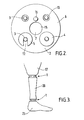
- the top part of fig. 2 shows the plate 6 and the bottom half the plate 2. Columns 3 are seen protruding through holes 13 in plate 6. A spacer 5 with its slot 12, nut 4 and central bore 7,15 are also seen in this figure.
- the prosthesis of fig. 3 includes socket 17, shin-tube 20 and foot member 23.
- the shin-tube may particularly be rotationally moulded.
- An alignment device 1 is connected between the socket 17 and the shin-tube 20 and between the shin-tube 20 and the foot member 23. The connection is made by a bolt 24 (not shown) extending from the socket 17 or foot member 23 into the shin-tube 20 through the central bore 7,15 of the device 1.
- the alignment device 1 shown in fig. 3 has no mounting plate 18 and therefore the plate 2 is directly attached to the shin-tube 20 or foot member 23, for example via a square boss on its lower surface corresponding to the boss 19 of the mounting plate 18.
- the central connecting bolt 24 is loosened. Opposite pairs of nuts 4 are raised or lowered by turning them using an Allen key engaging in the slot 11. This movemenbtilts the plate 6 and provides adjustment in two perpendicular planes. When the required adjustment has been achieved, the gap between each nut 4 and the plate 2 is filled with one or more spacers 5. Spacers of a suitable thickness are chosen to completely fill the gap. The bolt 24 is then tightened up again.
- the alignment device and socket can be rotated by a given amount by moving the plate 2 around a given number of the tongues or grooves 22.
- the spacers provide a load-bearing support between the nut 4 and the plate 2 so that the column 3 itself does not support the load. Since the device is made of plastics, the threaded engagement (or other means by which the nuts are adjustably supported on the columns) between the nuts 4 and the columns 3 is not itself strong enough to support the weight of the patient.
- the spacers provide a clear calibration of the alignment since the prosthetist can quickly see the number and size of spacers on each column.
- the spacers may each be a given number of millimeters thick. The difference in thickness of spacers on opposite rods can immediately be translated into a given tilt angle in each plane. The entire length of the prosthesis may easily be adjusted by adding a spacer of equal thickness to each column.
- a particular advantages of the described alignment device is its low overall height. Its simple design and assembly offers the potential for low cost manufacture by injection moulding or batch production by machining.
- body members of the invention need not be in the form of plates; they may be parts of the prosthesis itself.
Landscapes
- Health & Medical Sciences (AREA)
- Cardiology (AREA)
- Oral & Maxillofacial Surgery (AREA)
- Transplantation (AREA)
- Engineering & Computer Science (AREA)
- Biomedical Technology (AREA)
- Heart & Thoracic Surgery (AREA)
- Vascular Medicine (AREA)
- Life Sciences & Earth Sciences (AREA)
- Animal Behavior & Ethology (AREA)
- General Health & Medical Sciences (AREA)
- Public Health (AREA)
- Veterinary Medicine (AREA)
- Prostheses (AREA)
Applications Claiming Priority (2)
| Application Number | Priority Date | Filing Date | Title |
|---|---|---|---|
| GB8408661 | 1984-04-04 | ||
| GB08408661A GB2156678B (en) | 1984-04-04 | 1984-04-04 | Proshetic alignment device |
Publications (2)
| Publication Number | Publication Date |
|---|---|
| EP0157621A2 true EP0157621A2 (de) | 1985-10-09 |
| EP0157621A3 EP0157621A3 (de) | 1986-09-24 |
Family
ID=10559150
Family Applications (1)
| Application Number | Title | Priority Date | Filing Date |
|---|---|---|---|
| EP85302259A Withdrawn EP0157621A3 (de) | 1984-04-04 | 1985-04-01 | Vorrichtung zum Ausrichten einer Prothese |
Country Status (2)
| Country | Link |
|---|---|
| EP (1) | EP0157621A3 (de) |
| GB (1) | GB2156678B (de) |
Cited By (2)
| Publication number | Priority date | Publication date | Assignee | Title |
|---|---|---|---|---|
| EP0284360A1 (de) * | 1987-03-24 | 1988-09-28 | J.E. HANGER & COMPANY LIMITED | Ausrichtvorrichtung und Herstellungsverfahren eines künstlichen Gliedes |
| US4988361A (en) * | 1988-07-08 | 1991-01-29 | Je Hanger & Company Limited | Turntable for artificial limb |
Family Cites Families (5)
| Publication number | Priority date | Publication date | Assignee | Title |
|---|---|---|---|---|
| US3273168A (en) * | 1963-06-21 | 1966-09-20 | Henry F Gardner | Adjustable alignment coupling for lower extremity prostheses |
| GB1114312A (en) * | 1964-07-24 | 1968-05-22 | Vessa Ltd | Alignment devices for use with limb prostheses |
| GB2014855B (en) * | 1978-02-13 | 1982-07-28 | Secr Social Service Brit | Artificial legs |
| GB2114447B (en) * | 1982-02-12 | 1984-10-31 | Blatchford & Sons Ltd | Artificial leg alignment coupling |
| FR2530945B1 (fr) * | 1982-07-30 | 1986-04-18 | Proteor Sa | Dispositif de recherche d'alignement, d'alignement et d'orientation d'une prothese pour amputation de cuisse ou de jambe |
-
1984
- 1984-04-04 GB GB08408661A patent/GB2156678B/en not_active Expired
-
1985
- 1985-04-01 EP EP85302259A patent/EP0157621A3/de not_active Withdrawn
Cited By (2)
| Publication number | Priority date | Publication date | Assignee | Title |
|---|---|---|---|---|
| EP0284360A1 (de) * | 1987-03-24 | 1988-09-28 | J.E. HANGER & COMPANY LIMITED | Ausrichtvorrichtung und Herstellungsverfahren eines künstlichen Gliedes |
| US4988361A (en) * | 1988-07-08 | 1991-01-29 | Je Hanger & Company Limited | Turntable for artificial limb |
Also Published As
| Publication number | Publication date |
|---|---|
| EP0157621A3 (de) | 1986-09-24 |
| GB2156678B (en) | 1987-06-10 |
| GB2156678A (en) | 1985-10-16 |
| GB8408661D0 (en) | 1984-05-16 |
Similar Documents
| Publication | Publication Date | Title |
|---|---|---|
| CA2169238C (en) | Manhole head assembly | |
| US5047063A (en) | Adjustment device for artificial limbs | |
| US5104075A (en) | Machine leveling device | |
| US6189843B1 (en) | Linear motion table leg | |
| US4653709A (en) | Tilt-pan head for cameras | |
| US5080319A (en) | Adjustable position mounting device and method | |
| US9132998B2 (en) | Adjustable bearing foot | |
| EP0888514A1 (de) | Verstellfuss mit dichtungen | |
| US6150619A (en) | Support base for a measuring cell | |
| EP0157621A2 (de) | Vorrichtung zum Ausrichten einer Prothese | |
| EP0306776B1 (de) | Montagetreppeneinheit für eine Treppe | |
| US4196522A (en) | Alignment fixture | |
| US4511108A (en) | Locking device for the assembling of modular elements of pieces of furniture | |
| US3006606A (en) | Leveling device | |
| KR20000010508U (ko) | 높이 조절형 하중 지지대 | |
| EP1153333A1 (de) | Nivellierungskopf für kamera | |
| CN214143354U (zh) | 一种支座快速安装更换装置 | |
| EP0094204B1 (de) | Vorrichtung zum Konzentrieren und Sammeln von Sonnenstrahlung | |
| US6095786A (en) | Substrate forming mold, and plate thickness adjusting method of formed substrate in substrate forming mold | |
| EP0491206B1 (de) | Justierbare Konsole | |
| CA2151390A1 (en) | Three-dimensional grid structure with a joint | |
| JPH0743182Y2 (ja) | マンホールの受枠取付構造 | |
| SE455004B (sv) | Sett att festa en pelare pa ett fundament | |
| FI70290B (fi) | Laosanordning foeretraedesvis foer i ett fundament placerad stlpe | |
| GB2043823A (en) | Joint for Chair Legs |
Legal Events
| Date | Code | Title | Description |
|---|---|---|---|
| PUAI | Public reference made under article 153(3) epc to a published international application that has entered the european phase |
Free format text: ORIGINAL CODE: 0009012 |
|
| AK | Designated contracting states |
Designated state(s): AT BE CH DE FR GB IT LI LU NL SE |
|
| PUAL | Search report despatched |
Free format text: ORIGINAL CODE: 0009013 |
|
| AK | Designated contracting states |
Kind code of ref document: A3 Designated state(s): AT BE CH DE FR GB IT LI LU NL SE |
|
| RBV | Designated contracting states (corrected) |
Designated state(s): AT BE CH DE FR IT LI NL SE |
|
| STAA | Information on the status of an ep patent application or granted ep patent |
Free format text: STATUS: THE APPLICATION HAS BEEN WITHDRAWN |
|
| 18W | Application withdrawn |
Withdrawal date: 19861103 |
|
| RIN1 | Information on inventor provided before grant (corrected) |
Inventor name: WILKINSON, DEREK JAMES Inventor name: COOMBES, ALLAN GERALD ARTHUR |