EP0157678A2 - Elektronisches Endoskop - Google Patents
Elektronisches Endoskop Download PDFInfo
- Publication number
- EP0157678A2 EP0157678A2 EP85400471A EP85400471A EP0157678A2 EP 0157678 A2 EP0157678 A2 EP 0157678A2 EP 85400471 A EP85400471 A EP 85400471A EP 85400471 A EP85400471 A EP 85400471A EP 0157678 A2 EP0157678 A2 EP 0157678A2
- Authority
- EP
- European Patent Office
- Prior art keywords
- electronic endoscope
- endoscope according
- sensor
- control unit
- unit
- Prior art date
- Legal status (The legal status is an assumption and is not a legal conclusion. Google has not performed a legal analysis and makes no representation as to the accuracy of the status listed.)
- Withdrawn
Links
Images


Classifications
-
- G—PHYSICS
- G01—MEASURING; TESTING
- G01N—INVESTIGATING OR ANALYSING MATERIALS BY DETERMINING THEIR CHEMICAL OR PHYSICAL PROPERTIES
- G01N21/00—Investigating or analysing materials by the use of optical means, i.e. using sub-millimetre waves, infrared, visible or ultraviolet light
- G01N21/84—Systems specially adapted for particular applications
-
- A—HUMAN NECESSITIES
- A01—AGRICULTURE; FORESTRY; ANIMAL HUSBANDRY; HUNTING; TRAPPING; FISHING
- A01G—HORTICULTURE; CULTIVATION OF VEGETABLES, FLOWERS, RICE, FRUIT, VINES, HOPS OR SEAWEED; FORESTRY; WATERING
- A01G7/00—Botany in general
-
- G—PHYSICS
- G02—OPTICS
- G02B—OPTICAL ELEMENTS, SYSTEMS OR APPARATUS
- G02B23/00—Telescopes, e.g. binoculars; Periscopes; Instruments for viewing the inside of hollow bodies; Viewfinders; Optical aiming or sighting devices
- G02B23/24—Instruments or systems for viewing the inside of hollow bodies, e.g. fibrescopes
- G02B23/2476—Non-optical details, e.g. housings, mountings, supports
-
- G—PHYSICS
- G01—MEASURING; TESTING
- G01N—INVESTIGATING OR ANALYSING MATERIALS BY DETERMINING THEIR CHEMICAL OR PHYSICAL PROPERTIES
- G01N21/00—Investigating or analysing materials by the use of optical means, i.e. using sub-millimetre waves, infrared, visible or ultraviolet light
- G01N21/84—Systems specially adapted for particular applications
- G01N2021/8466—Investigation of vegetal material, e.g. leaves, plants, fruits
Definitions
- the present invention is in the field of exploration which is difficult to reach. More precisely, it aims at an electronic endoscope which can be used for different uses, in particular in botany, geology, agriculture, archeology and other sciences requiring a precise exploration of these framed sites, for example underground or intra-corporeal.
- a first object of the invention is to produce an electronic endoscope for the study and observation of difficult-to-reach sites, an apparatus which, bypassing the drawbacks of the devices of the prior art, allows the implementation of a method not destructive of the site to explore.
- a second object of the invention is to produce an electronic endoscope allowing the study of a site at the level of a transparent wall in contact with the latter.
- a third object of the invention is to provide an electronic endoscope for analyzing and processing in digital data the information collected at the site to be explored.
- a fourth object of the invention is to produce an electronic endoscope comprising a drive device automatically moving the exploration means along the transparent wall in contact with the site to be explored.
- the laser diode is associated with focusing means and coupled to a photodetector intended to regulate the light flux emitted by said laser diode.
- the members imparting a movement relative to the sensor are constituted by a threaded axis cooperating with a hollow shaft longitudinally split so as to produce a relative movement of smaller pitch than the helical pitch.
- the online processing unit consists of a microprocessor, while the control unit consists of a microcomputer, these two units being connected to each other by a bus.
- the storage unit advantageously consists of a series of single-sided, double-density flexible disks.
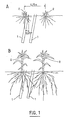
- Stage A represents an early stage of corn growth, while stage B represents a later stage. In both cases and more particularly in stage B, the roots of the respective plants come into contact with the tubes 1.
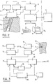
- FIG. 2 there is also seen a tube 1 inside which is placed a sensor 3 connected to a stepping motor 4 by a positioning and driving rod 3a.
- the motor 4 is associated with a unit for measuring its rotational speed and for detecting the end of the line 5, itself connected to an on-line processing unit 6 which on the one hand cooperates with a control unit 7 and d on the other hand to a motor control unit 8.
- the control unit 7 cooperates with a logic processing unit 9, and is also connected to a storage unit 10 and to display means 11.
- the sensor 3 consists of an emitter 12, for example a laser diode whose light flux is focused by an optic 13 before crossing the wall of the tube 1 and coming to meet a root 14 of the ground in contact with the tube 1, and a photoreceptor 15 receiving the light flux reflected by the root 14.
- the laser diode 12 is associated with an optical power control device.
- the photoreceptor 15 transmits a signal corresponding 16 to the light flux reflected to a digitization unit 17 where the signal thus obtained is digitalized under 8 bits and transmitted by the uni transmission tee 18 under 1 bit to the on-line processing unit 6.
- the digitization 17 and transmission 18 units cooperate according to departure paths f 1 , occupation f 2 , synchronization f 3 with delay units 19 and logic synchronization 20, associated with a clock 21.
- the electronic system of the sensor 3 is essentially divided into three parts.
- the first part is constituted by a device making it possible to obtain a stabilized supply, and which transforms the input voltage (15 volts + 2 volts) into two output voltage / 4.6 and 9.6 volts relative to the ground electronic (0 volt) _7.
- the voltage of 4.6 volts is taken as the voltage reference for the logic of digitization and transmission (17, 18) of the acquired signals, which makes it possible to obtain the virtual supply voltages of 5 volts (TTL power supply) and 4.6 volts (analog reference voltage of analog / digital converter 22; pin 22a).
- This assembly is used to satisfy the three voltage levels necessary for the sensor 3 and to limit to two the number of electrical transmission systems per ring and brush between the in-line transmission unit 6 and the sensor 3.
- the second part of the electronic system consists of a device for controlling the light intensity of the laser diode 12, which is coupled to a photodetector 23, which makes it possible to regulate the light flux of the diode in order to overcome in particular effects related to temperature variations. If, for one reason or another, this flux decreases then the photodetector 23 will conduct less current, which will lead to a decrease in the voltage across the resistor 24. This decrease will cause through the amplifier 25 an increase of the conduction of transistor 26, therefore an increase in the luminous flux of the diade12.
- the third part of the electronic system of the sensor is constituted by a logic system of digitalisa tion and transmission of acquired signals (referenced 17, 18 in Figure 3).
- This system is itself divided into four parts, namely a circuit for transforming the light signal into an electrical signal constituted by the photoreceptor 15 and the operational amplifier 27; a second signal digitization circuit is represented by the analog / digital converter 22; a third transmission circuit
- the fourth synchronization circuit or unit consists of a clock 21, a sequencer-divider 28 which controls the moment of the analog / digital conversion and the synchronous operation between the analog / digital converter 22 and the asynchronous reception unit / transmission 18, via conventional integration differentiation and signal shaping circuits.
- the mechanical drive and positioning unit of the sensor consists of a stepping electric motor 4 on the driving shaft of which are carried, on the one hand a primary pinion 31 meshing with a primary wheel 33 which drives a primary shaft 34 to which a split tubular shaft 35 is connected, and on the other hand a secondary pinion 36 meshing with a secondary wheel 32 which drives the secondary shaft 37 and connected to a threaded rod 38 disposed concentrically with the split shaft 35.
- the relative movement of the threaded rod 38 the speed of rotation of which is 0.75 times that of the split shaft 35 itself rotating at the speed of the motor 4, makes it possible to obtain a displacement of the sensor 3 according to a helical movement of a step of 0.2 mm. It is conceivable that the device of FIG. 5 can be associated with extensions making it possible to increase the depth explored by the sensor 3 in the tubes 1.
- Figures 6 and 7 show respectively in section and in perspective, the support element of the sensor 3 which will be arranged in the interval between two flanges 39, 40 secured by the spacers 41, 42, 43 one of which 43 is a spacer d drive keyed by a nipple 4 & to the shaft split 35 and meshing with the threaded rod 38.
- the assembly of the sensor support can thus slide in the tube 1.
- FIG. 8 shows the speed measurement and image synchronization unit, this unit allowing synchronization of the motor speed and the data acquisition frequency. Indeed mitante li- speed for data acquisition is that of fo r - the image to form on the graphical console 11 constituting the display means.
- This unit makes it possible to adapt the speed of data acquisition, as a function of the speed of the motor 4, to that of the formation of the image on the graphic console 11.
- This unit consists of an optical sensor 45 whose signal is then amplified by the amplifier 46 and the differential amplifier 47, then filtered by means of a low-pass filter of the fourth order 48 cooperating with the current transmission unit 49 to send said signal to the online processing unit 6.
- the sensor is activated by a reflector 50 fixed to a pinion 51 secured to the axis of rotation of the motor 4.
- the motor 4 is controlled by the motor control unit 52, this control being carried out via the intensity and not the voltage of the current, which makes it possible to work quickly and at long distance.
- This unit is controlled by the online processing unit 6.
- the speed measurement and image synchronization unit After each engine revolution (after recording a data line), the speed measurement and image synchronization unit, as shown in Figure 9, sends an electrical signal to the online processing unit 6 guaranteeing the computer the change of line and allowing it to check the angular speed and the proper functioning of the motor 4.
- the circuit is supplied at 15 volts by the power supply unit 52 via the filter capacitors C 13 C 14 ' C 15' C 16 ' C 18 .
- the light intensity of the electric diode troluminescent 53 is fixed by the resistor R 17 , the current of the receiving diode 54 is amplified by the transistor 55 (counter-reacted by the resistor R 20 in order to stabilize the operating point) internal to the sensor 3 before being taken into account counts by a differential amplifier with high input impedance 56, 57.
- the signal which is very noisy because of the proximity of the motor 4, is smoothed by two low-pass filters of the second order in cascade 58, 59.
- the second filter, amplifier 59 delivers an output signal which switches between 0 and 15 volts.
- FIG. 10 is shown a block diagram of the on-line processing unit 6, allowing the endoscope to reach the fixed goal, which is to store in a magnetic memory a digital image of the roots in contact with the wall. of tubes implanted in the ground, this image being subjected to further processing and being able to be viewed on a graphic screen.
- process control i.e. the serial arrival of the data supplied by the sensor, control of the position of the sensor, management of line-image / motor synchronization, motor control .
- Data processing and filtering i.e. digital filtering of the image with respect to a gray level selected in the light of the optical density curves which the device makes it possible, the formatting of the data and the routing of the data and process status information to the control unit.
- the asynchronous reception and transmission unit 75 which transforms the serial data coming from the sensor into parallel data (5bits or more).
- the line-image / motor synchronization circuit the data coming from the asynchronous reception / transmissive unit 75 and from the synchronization circuit 64 pass through the port A of the circuit 61 before being taken into account by the unit central 60.
- the amplification and shaping circuits for the stepper motor control unit - the motor control return signals as well as the sensor position control signal 3- pass through port E to the central unit 60.
- the serial / parallel conversion frequency is provided by the internal clock of circuit 61, while the speed of rotation of the stepping motor is dictated and then verified by the clocks of circuit 65.
- the circuits allowing the connections with the control unit 7 are produced through a CAMAC bus not shown in the drawings.
- the data coming from the sensor 3, passing through the port A, are filtered and formatted by the central unit 60 and then stored in the buffer memories 62. They are then sent to the control unit 7 through the registers "L- data "70 and the" synchro-data "circuits 71 also of the same type and according to the same procedures.
- the access time to the memories 72 being slow compared to the elementary cycle of the central unit, the latter is synchronized by a "synchro-. EPROM" circuit 73.
- the number of peripherals connected to the unit central being important, it is necessary to amplify the bus output by amplifiers.
- the central unit 60 is also initialized according to the needs of the control unit 7 by the "INIT" circuit 74.
- FIG. 11 represents a general operating model of the Rhizoscope in which a represents the supply of the sensors, b the recording of the data, c the limit switch of the sensor, d the piloting bus of the engine control unit, e the motor supply and f the end of line detector. It is clear that this model can be generalized to other types of use of the control unit 7. On the other hand, in the current scheme, only one execution station operates, the online unit. Extensions can be envisaged by creating other stations, for example by simultaneous acquisition on several tubes 1 from several sensors 3.
- control unit constitutes, in the apparatus of the invention, the executive in a work structure designed according to a hierarchical control model (see FIG. 11).
- the entire system has been organized so that the operator using the instrument in the field can intervene regularly to check that it is working properly and set certain parameters, for example root detection thresholds and the like.
- the data transmitted by the online processing unit to the control unit can be viewed as described above by means of a graphic console 11, possibly associated with an image copying printer, not used in the field. , which is used on the one hand for the conversation between the operator and the control unit and, on the other be part, to the visualization of the results.
- Image processing software has been designed specifically for this use, however it can be used for multiple other applications.
- this endoscope comprising a laser emitting diode
- the incident light is diffused by the site to be explored, which makes it particularly visible, this laser diode being associated with a photosensitive device, for example a photoreceptor.
- the device of the present invention can be associated with any automated means and controlled by the control unit, for example telescopic devices for positioning the sensor servo assembly, devices for carousel allowing automatic movement and positioning of the sensor and the like, and is not limited to the study of rooting of plants.
Landscapes
- Physics & Mathematics (AREA)
- Life Sciences & Earth Sciences (AREA)
- General Physics & Mathematics (AREA)
- Forests & Forestry (AREA)
- Health & Medical Sciences (AREA)
- Environmental Sciences (AREA)
- Botany (AREA)
- Astronomy & Astrophysics (AREA)
- Biodiversity & Conservation Biology (AREA)
- Optics & Photonics (AREA)
- Ecology (AREA)
- Chemical & Material Sciences (AREA)
- Analytical Chemistry (AREA)
- Biochemistry (AREA)
- General Health & Medical Sciences (AREA)
- Immunology (AREA)
- Pathology (AREA)
- Instruments For Viewing The Inside Of Hollow Bodies (AREA)
- Endoscopes (AREA)
Applications Claiming Priority (2)
| Application Number | Priority Date | Filing Date | Title |
|---|---|---|---|
| FR8403862A FR2558257B1 (fr) | 1984-01-13 | 1984-01-13 | Endoscope electronique |
| FR8403862 | 1984-03-13 |
Publications (2)
| Publication Number | Publication Date |
|---|---|
| EP0157678A2 true EP0157678A2 (de) | 1985-10-09 |
| EP0157678A3 EP0157678A3 (de) | 1986-08-13 |
Family
ID=9301982
Family Applications (1)
| Application Number | Title | Priority Date | Filing Date |
|---|---|---|---|
| EP85400471A Withdrawn EP0157678A3 (de) | 1984-01-13 | 1985-03-12 | Elektronisches Endoskop |
Country Status (2)
| Country | Link |
|---|---|
| EP (1) | EP0157678A3 (de) |
| FR (1) | FR2558257B1 (de) |
Cited By (3)
| Publication number | Priority date | Publication date | Assignee | Title |
|---|---|---|---|---|
| EP0770321A1 (de) * | 1995-10-23 | 1997-05-02 | Haindl, Leopold jun. | Einrichtung zur Feststellung der Position von Spargelpflanzen |
| CN103364399A (zh) * | 2013-07-12 | 2013-10-23 | 北京农业信息技术研究中心 | 作物根系生长探测系统及探测方法 |
| WO2021151280A1 (zh) * | 2020-01-29 | 2021-08-05 | 南京农业大学 | 一种田间作物根系表型的多通道获取系统及安装方法 |
Families Citing this family (1)
| Publication number | Priority date | Publication date | Assignee | Title |
|---|---|---|---|---|
| CN105929137B (zh) * | 2016-06-13 | 2019-04-30 | 福建农林大学 | 绘制根际平面pH分布图的装置及方法 |
Family Cites Families (6)
| Publication number | Priority date | Publication date | Assignee | Title |
|---|---|---|---|---|
| US2922844A (en) * | 1957-02-14 | 1960-01-26 | Sheldon Edward Emanuel | Endoscopic devices |
| DE2702332C3 (de) * | 1977-01-21 | 1980-09-25 | Deutsche Forschungs- Und Versuchsanstalt Fuer Luft- Und Raumfahrt E.V., 5000 Koeln | Verfahren zur chemischen und mineralogischen Analyse des Erdbodens |
| SE439377B (sv) * | 1978-07-26 | 1985-06-10 | Hitachi Ltd | Anordning for optisk inspektion av rorledningar |
| EP0050922B1 (de) * | 1980-10-27 | 1985-01-16 | Sumitomo Electric Industries Limited | Beobachtungssystem für die Untersuchung kleiner Öffnungen |
| JPS57204509A (en) * | 1981-06-11 | 1982-12-15 | Bekutoronikusu Inc | Scanning method and apparatus |
| JPS5810032A (ja) * | 1981-07-09 | 1983-01-20 | オリンパス光学工業株式会社 | 内視鏡 |
-
1984
- 1984-01-13 FR FR8403862A patent/FR2558257B1/fr not_active Expired
-
1985
- 1985-03-12 EP EP85400471A patent/EP0157678A3/de not_active Withdrawn
Cited By (4)
| Publication number | Priority date | Publication date | Assignee | Title |
|---|---|---|---|---|
| EP0770321A1 (de) * | 1995-10-23 | 1997-05-02 | Haindl, Leopold jun. | Einrichtung zur Feststellung der Position von Spargelpflanzen |
| CN103364399A (zh) * | 2013-07-12 | 2013-10-23 | 北京农业信息技术研究中心 | 作物根系生长探测系统及探测方法 |
| CN103364399B (zh) * | 2013-07-12 | 2015-06-17 | 北京农业信息技术研究中心 | 作物根系生长探测系统及探测方法 |
| WO2021151280A1 (zh) * | 2020-01-29 | 2021-08-05 | 南京农业大学 | 一种田间作物根系表型的多通道获取系统及安装方法 |
Also Published As
| Publication number | Publication date |
|---|---|
| EP0157678A3 (de) | 1986-08-13 |
| FR2558257A1 (fr) | 1985-07-19 |
| FR2558257B1 (fr) | 1986-08-08 |
Similar Documents
| Publication | Publication Date | Title |
|---|---|---|
| EP0126682B1 (de) | Verfahren und Vorrichtung zur Festlegung der für Datenaufnahme auf eine optische Scheibe aufgebrachten optischen Leistung | |
| EP0278882B1 (de) | Verfahren und Vorrichtung zum Erstellen eines Abdrucks für medizinische Zwecke | |
| FR2491250A1 (fr) | Balayage a point mobile a grandeur de champ arbitrairement forme | |
| EP0158549B1 (de) | Endoskopartige Vorrichtung zur unterirdischen Erforschung, insbesondere zur insitu Wahrnehmung der Einwurzelung von Pflanzen | |
| US20100314533A1 (en) | Scanning microscope and method of imaging a sample | |
| EP0485265B1 (de) | Verfahren und Methode zur zerstörungsfreien Prüfung mit gleichzeitiger Aufnahme von Röntgendaten und tomographischen Daten | |
| FR2665600A1 (fr) | Procede de detection pour camera panoramique, camera pour sa mise en óoeuvre, et systeme de veille equipe d'une telle camera. | |
| EP0178954A2 (de) | Verfahren und Einrichtung zur Abtastung eines Fensters im Bildbereich einer bildorganisierten Ladungsübertragungsanordnung | |
| FR2551237A1 (fr) | Procede et dispositif pour traiter des informations graphiques pour la reproduction d'images | |
| EP1740974A1 (de) | Verfahren und system zur messung der geschwindigkeit einer blutströmung | |
| EP0093649A1 (de) | Verfahren zur röntgenologischen Bildverarbeitung für die Korrektur von durch Streustrahlung verursachten Bildfehlern | |
| EP3720115A1 (de) | Bildgebungsverfahren mit gepulstem licht | |
| EP0157678A2 (de) | Elektronisches Endoskop | |
| EP0328443B1 (de) | Verfahren zum Digitalisieren der Oberfläche eines dreidimensionalen Gegenstandes und Aufnahmevorrichtung zur Anwendung dieses Verfahrens | |
| FR2487511A1 (fr) | Spectrophotometre pour longueurs d'onde multiples et hacheur utilisable avec cet appareil | |
| FR2593986A1 (fr) | Systeme de lecture rapide d'un capteur optique matriciel a transfert de charges organise en transfert de trame monocoup pour la detection video d'images breves | |
| FR2830629A1 (fr) | Procede et dispositif de prelevement d'une partie d'un faisceau lumineux, notamment pour appareil d'analyse de fluorescence | |
| CA1244920A (fr) | Procede d'extension de la gamme des frequences des recurrences radar acceptables par un transformateur numerique d'images et moyens de mise en oeuvre de ce procede | |
| EP0604302B1 (de) | Verfahren und Vorrichtung zur Analyse von sich bewegenden Objekten mittels Radiographie | |
| EP1579260A1 (de) | Paralleles konfokales lasermikroskopiesystem auf der basis von vcsel-technologie | |
| FR2612647A1 (fr) | Dispositif de modulation pour un dispositif detecteur de rayonnement captant un champ d'image | |
| EP0130131B1 (de) | System zum Aufnehmen von Plänen | |
| EP3123462B1 (de) | Anzeigesteuerungsverfahren und vorrichtung zur durchführung dieses verfahrens | |
| EP0076180A2 (de) | Verfahren und Gerät zur Erzeugung tomographischer Abbildungen | |
| FR2485749A1 (fr) | Dispositif pour determiner a chaque instant la position d'un objet en mouvement |
Legal Events
| Date | Code | Title | Description |
|---|---|---|---|
| PUAI | Public reference made under article 153(3) epc to a published international application that has entered the european phase |
Free format text: ORIGINAL CODE: 0009012 |
|
| AK | Designated contracting states |
Designated state(s): AT BE CH DE GB IT LI LU NL SE |
|
| PUAL | Search report despatched |
Free format text: ORIGINAL CODE: 0009013 |
|
| AK | Designated contracting states |
Kind code of ref document: A3 Designated state(s): AT BE CH DE GB IT LI LU NL SE |
|
| 17P | Request for examination filed |
Effective date: 19860820 |
|
| 17Q | First examination report despatched |
Effective date: 19870710 |
|
| STAA | Information on the status of an ep patent application or granted ep patent |
Free format text: STATUS: THE APPLICATION IS DEEMED TO BE WITHDRAWN |
|
| 18D | Application deemed to be withdrawn |
Effective date: 19880121 |
|
| RIN1 | Information on inventor provided before grant (corrected) |
Inventor name: SCHULTZ, GUY Inventor name: PICARD, DIDIER Inventor name: MANANTSOA, VICTOR Inventor name: HUEBER, JEAN |