EP0157714A1 - Bremse für Angelwinden - Google Patents
Bremse für Angelwinden Download PDFInfo
- Publication number
- EP0157714A1 EP0157714A1 EP85420057A EP85420057A EP0157714A1 EP 0157714 A1 EP0157714 A1 EP 0157714A1 EP 85420057 A EP85420057 A EP 85420057A EP 85420057 A EP85420057 A EP 85420057A EP 0157714 A1 EP0157714 A1 EP 0157714A1
- Authority
- EP
- European Patent Office
- Prior art keywords
- lever
- spring
- braking
- reel
- brake
- Prior art date
- Legal status (The legal status is an assumption and is not a legal conclusion. Google has not performed a legal analysis and makes no representation as to the accuracy of the status listed.)
- Granted
Links
- 230000005540 biological transmission Effects 0.000 claims abstract description 8
- 230000006835 compression Effects 0.000 claims description 5
- 238000007906 compression Methods 0.000 claims description 5
- 230000000694 effects Effects 0.000 claims description 5
- 230000036316 preload Effects 0.000 claims 1
- 241000251468 Actinopterygii Species 0.000 description 3
- 238000004519 manufacturing process Methods 0.000 description 2
- 238000011084 recovery Methods 0.000 description 2
- 239000010425 asbestos Substances 0.000 description 1
- 238000005266 casting Methods 0.000 description 1
- 238000006243 chemical reaction Methods 0.000 description 1
- 238000006073 displacement reaction Methods 0.000 description 1
- 239000010985 leather Substances 0.000 description 1
- 239000000463 material Substances 0.000 description 1
- 238000000034 method Methods 0.000 description 1
- 230000003071 parasitic effect Effects 0.000 description 1
- -1 polytetrafluoroethylene Polymers 0.000 description 1
- 229920001343 polytetrafluoroethylene Polymers 0.000 description 1
- 239000004810 polytetrafluoroethylene Substances 0.000 description 1
- 238000003825 pressing Methods 0.000 description 1
- 229910052895 riebeckite Inorganic materials 0.000 description 1
- 238000003860 storage Methods 0.000 description 1
Images

Classifications
-
- A—HUMAN NECESSITIES
- A01—AGRICULTURE; FORESTRY; ANIMAL HUSBANDRY; HUNTING; TRAPPING; FISHING
- A01K—ANIMAL HUSBANDRY; AVICULTURE; APICULTURE; PISCICULTURE; FISHING; REARING OR BREEDING ANIMALS, NOT OTHERWISE PROVIDED FOR; NEW BREEDS OF ANIMALS
- A01K89/00—Reels
- A01K89/02—Brake devices for reels
- A01K89/027—Brake devices for reels with pick-up, i.e. for reels with the guiding member rotating and the spool not rotating during normal retrieval of the line
Definitions
- the present invention relates to reels to launch for fishing, and more particularly those called fixed reel, and provided with a brake controlled from the rear of the reel.
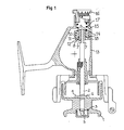
- Figure 1 shows a sectional view of a reel of this type widely known and used.
- the wire reserve called spool or drum 1 is a substantially revolution part consisting of two flanges extended radially joined by a cylindrical hub extending axially from one flange to the other.
- the axis of the spool is approximately parallel to the direction of unwinding of the wire.
- the spool of thread is fixed in rotation both during casting and during recovery.
- a crank rotates a thread catcher which turns around the spool and winds the thread.
- the spool ceases to be fixed if the tension of the wire exceeds a limit value chosen by the fisherman.
- the spool 1 is connected to the casing 13 of the reel by means of a kinematic chain which comprises at least one force limiting device, also called a brake.
- the coil 1 is mounted on the axis 2 by means of a clip 3 and a groove 4 cooperating respectively with the groove 5 and the pin 6 of the axis.
- the axis has an alternative axial translational movement under the action of a wire storage system not shown in the figure.
- the axis slides for this at its other end in a socket 8 with which it is made integral in rotation by two dishes 7 of the axis in engagement with corresponding internal dishes of the socket 8.
- the exterior surface of the socket 8 comprises two dishes 9, and receives washers 10 whose central hole has a section corresponding to the outside section of the socket to slide axially thereon without the possibility of rotation.
- the sleeve includes a flange 11 bearing against a part forming an abutment 18 of the casing 13. And a cylindrical seat 12 engaged in a bore of this same part 18 of the casing for centering the sleeve.
- Washers 14, mounted idly on the sleeve, interposed between the washers 10, have a radial extension which engages in a groove 15 of the casing to prevent their rotation.
- the washers 10 and 14 have suitable friction qualities.
- the socket assembly 8, washers 10 and washers 14 is compressed axially between the stop part 18 of the casing and a first spring 17 pushed back by a nut 16 for adjusting the braking torque.
- the nut 16 is accessible from the rear of the reel, so that it is not likely to be confused with the means for changing the spool, generally disposed at the front, its grip is facilitated by its suitable size, and it is not disturbed by the random presence of the wire.
- Patent FR-E- 77 644 ROUANET disclosed a main drag reel controlled from the side by means of a screw urging, by means of a spring, a brake shoe bearing against the external surface of a socket integral in rotation with the coil.
- This device also comprises an auxiliary brake, actuated by a lever, one end of which is maneuvered by the operator and the other end of which rests on the main brake shoe.
- auxiliary brake lever has a practically zero stroke, which makes it very difficult to adjust the braking torque, especially in the fishing sector where reactions must be quick and precise; moreover, no means limit the auxiliary braking torque, and it has been observed that the use of such a device leads to frequent wire breaks; in addition the imbalance of the lever produces, by the effect of its weight, parasitic braking depending on the orientation of the reel. Note that this auxiliary brake structure is not directly applicable to a main washer type brake.
- the subject of the present invention is in particular the production of additional braking means in which the stroke of the lever is non-zero and also independent of the adjustment of the rear brake. position of the lever rather than the pressure force exerted on it by the hand.
- These means can be actuated by an elastic return lever to ensure immediate and simple efficiency.
- the invention also allows these additional braking operations to be carried out using a very small number of additional parts, in particular by using certain parts of the rear brake according to a double function, and according to a structure compatible with the rear brake reels of the washer type.
- the position of the lever is independent of the rear brake adjustment, and in particular its position at rest is always the same.
- the fisherman thus has the possibility of appreciating sensitively the additional braking which it causes by simply locating the effort which it exerts on the lever.
- the additional braking means according to the invention make it possible in particular to make the additional braking torque substantially proportional to the sole movement of the lever, and this independently of the adjustment of the rear brake and over the entire usual range for adjusting this brake.
- the breaking of the wire is avoided according to the invention by providing means limiting at any time the maximum additional braking torque provided by the additional brake.
- the lever is mounted oscillating between a first fixed stop of the casing against which it is returned by the elastic return means, and a second fixed stop of the casing limiting its maximum stroke; thus, the combination of the second fixed stop and the elastic transmission means limits the compression force produced by the lever on the braking member more precisely, and prevents the production of an excessively high additional braking torque, which would cause the wire to break.
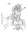
- the rear brake has exactly the same constitution as in the known devices of FIG. 1.
- the reel according to the invention comprises an auxiliary braking lever 20, articulated on the casing 13 along a transverse axis of rotation 21.
- the lever is disposed in a longitudinal position substantially parallel to the rod on which the reel is to be mounted, so as to be maneuvered directly by the hand holding the cane.
- the lever 20 can oscillate between a first fixed stop 22 of the casing 13 and a second fixed stop 23 of the casing.
- a tie rod 24 transmits the movements of the lever 20 at the first end 25 of a second spring 26, a tension spring, the second end 27 of which is hooked to a rocker 28.
- the tie rod 24 includes a threaded portion 29 in which engages a threaded screw 30, allowing its length adjustment.
- a third spring 31, compression spring has a first end bearing against a shoulder 32 of the tie rod 24 and a second end bearing against the casing 13. The third spring 31 exerts on the lever 20, in addition to the effect of the second spring 26, a restoring force towards the first fixed stop 22 of the casing, position in which the lever is at rest and the spring 26 has zero tension.
- the third spring 31 appreciably improves the sensitive effect perceived by the user during the operation of the lever: it is found in fact that, in the absence of a third spring 31, to produce the desired additional braking, it sufficient is a low tensile force of the spring 26, corresponding to a pressing force F of 50 to 100 Newton approximately at the end of the lever.
- the spring 31 is chosen so as to have a prestress, or non-zero residual tension in the rest position of the lever 20, and a stiffness such that it is necessary to apply to the end of the lever an increasing force of approximately 40 Newton to 150 Newton about to make it pass from the position of rest to the maximum braking.
- the rocker 28 comprises a first end 33 on which the spring 26 is hooked, and a second end 34 articulated in the casing 13.
- the rocker 28 can oscillate around its second end 34 by actuation of the lever.
- the second end 34 of the rocker is in unidirectional support on a shoulder 35 of the casing.
- the rocker 28 comprises a projecting central part 36 in contact with the stack of washers 10 and 14, and capable of pushing the washers against the stop 18 of the casing, under the action of one or two springs 17 and 26.
- the rocker 28 can have the shape of a washer, that is to say with a central light allowing the free passage of the sleeve 8.
- the central light is sufficiently large to also allow the passage of the spring 17 which comes into abutment either directly, or by means of a pusher not shown against the first washer of the stack of washers 10 and 14;
- the central lumen is narrower, so that the spring 17 or its pusher is in abutment against the rocker 28, itself in abutment against the stack of washers. The rocker 28, then inserted between the spring 17 and the stack of washers, transmits the pressure exerted by the spring 17 of the rear brake.
- the lever 20 can produce an additional braking torque: by actuation of the lever, the tie rod 24 causes the tension of the spring 26 which transmits a traction on the rocker 28 itself causing an increase compression of the stack of washers 10 and 14.
- the effect exerted by the lever 20 is limited by the combination of the stop 23 and the spring 26.
- the additional braking torque is substantially proportional to the angular displacement of the lever 20.
- the housing 13 comprises two parts, a first part 40 on which comes to fit a second part 41 forming a cover.
- the washers 10, rotary washers are slidably mounted on the bush 8 relative to which they are locked in rotation by dishes.
- the washers 14, or fixed washers, rotate freely in rotation and in translation relative to the sleeve 8, and slide relative to the housing 13 in which they are blocked in rotation by engagement in corresponding grooves 42 and 43 of the housing.
- the washers 14 have a substantially rectangular section, better represented in FIG. 3, and a circular central hole 44 with a diameter greater than the outside diameter of the sleeve 8.
- the washers 10 on the other hand have a circular section with an outside diameter less than the distance separating the bottoms from the grooves 42 and 43, and a central hole, the cross section of which includes dishes and corresponds to the external shape of the portion of the socket 8 on which they are engaged.
- each of the two parts 40 and 41 of the casing 13 has one of the two grooves 42 and 43.
- the washers 10 and 14 can be single or multiple, and can be separated by intermediate washers in a material with a suitable coefficient of friction, such as: leather, polytetrafluoroethylene, asbestos, felt, etc.
Landscapes
- Life Sciences & Earth Sciences (AREA)
- Environmental Sciences (AREA)
- Animal Husbandry (AREA)
- Biodiversity & Conservation Biology (AREA)
- Braking Arrangements (AREA)
Applications Claiming Priority (2)
| Application Number | Priority Date | Filing Date | Title |
|---|---|---|---|
| FR8405419A FR2561497B1 (fr) | 1984-03-26 | 1984-03-26 | Frein pour moulinet de peche au lancer |
| FR8405419 | 1984-03-26 |
Publications (2)
| Publication Number | Publication Date |
|---|---|
| EP0157714A1 true EP0157714A1 (de) | 1985-10-09 |
| EP0157714B1 EP0157714B1 (de) | 1989-04-26 |
Family
ID=9302884
Family Applications (1)
| Application Number | Title | Priority Date | Filing Date |
|---|---|---|---|
| EP85420057A Expired EP0157714B1 (de) | 1984-03-26 | 1985-03-25 | Bremse für Angelwinden |
Country Status (4)
| Country | Link |
|---|---|
| US (1) | US4634073A (de) |
| EP (1) | EP0157714B1 (de) |
| DE (1) | DE3569653D1 (de) |
| FR (1) | FR2561497B1 (de) |
Cited By (4)
| Publication number | Priority date | Publication date | Assignee | Title |
|---|---|---|---|---|
| EP0181027A3 (de) * | 1984-11-09 | 1987-01-21 | FABRIQUE NATIONALE HERSTAL en abrégé FN Société Anonyme | Bremse einer Angelwinde |
| US4725012A (en) * | 1986-06-30 | 1988-02-16 | Brunswick Corporation | Fishing reel drag with duplex control |
| FR2740003A1 (fr) * | 1995-10-23 | 1997-04-25 | Mitchell Sports | Moulinet de peche a frein superieur de bobine |
| CN102210290A (zh) * | 2010-04-08 | 2011-10-12 | 意大利渔具有限责任公司 | 用于钓鱼抛杆的、具有杠杆控制制动装置的鱼线轮 |
Families Citing this family (15)
| Publication number | Priority date | Publication date | Assignee | Title |
|---|---|---|---|---|
| US4746077A (en) * | 1985-05-30 | 1988-05-24 | Shimano Industrial Company Limited | Control device for a drag mechanism in a spinning type fishing reel |
| JPH0425972Y2 (de) * | 1985-12-27 | 1992-06-23 | ||
| US4778123A (en) * | 1986-07-21 | 1988-10-18 | Shimano Industrial Company Limited | Drag adjusting device for a closed-face type fishing reel |
| EP0639328B1 (de) * | 1989-11-17 | 1999-07-28 | Daiwa Seiko Inc. | Angelwinde |
| US5040743A (en) * | 1990-04-16 | 1991-08-20 | Zebco Corporation | Spinning reel with rear-actuated front drag |
| US5289991A (en) * | 1990-07-04 | 1994-03-01 | Shimano Inc. | Spinning reel |
| KR920003650Y1 (ko) * | 1990-08-31 | 1992-06-08 | 주식회사 은성사 | 낚시용 릴의 스풀제동력 절환장치 |
| JPH06245674A (ja) * | 1993-02-26 | 1994-09-06 | Daiwa Seiko Inc | 魚釣用スピニングリール |
| IT1274986B (it) * | 1994-12-16 | 1997-07-29 | Claudio Rosa | "perfezionamenti ai mulinelli da pesca" |
| JP3355063B2 (ja) * | 1995-06-13 | 2002-12-09 | 株式会社シマノ | スピニングリール |
| US5697566A (en) * | 1996-03-13 | 1997-12-16 | Charles C. Worth Corporation | Closed faced spinning reel with multiple function trigger |
| US5692691A (en) * | 1996-03-21 | 1997-12-02 | Charles C. Worth Corporation | Double trigger actuated reel |
| US5865388A (en) * | 1997-07-14 | 1999-02-02 | Yeh; Shih-Yuan | Fishing reel with a breaking device |
| FR2774860B1 (fr) * | 1998-02-16 | 2000-04-14 | Const Mecaniques Toulouse | Renvoi du systeme de freinage d'un moulinet de peche |
| GB2379370B (en) * | 2001-08-14 | 2006-02-01 | Michael Joseph Zabrana | Trigger hook |
Citations (11)
| Publication number | Priority date | Publication date | Assignee | Title |
|---|---|---|---|---|
| US1462387A (en) * | 1922-06-26 | 1923-07-17 | Budd E Slade | Straw spreader for harvesting and thrashing machines |
| GB470695A (en) * | 1936-12-12 | 1937-08-19 | Wenzel Thoner | Improvements relating to braking devices for fishing reels having fixed spindles |
| FR970757A (fr) * | 1948-08-14 | 1951-01-09 | Perfectionnement aux procédés et dispositifs de freinage pour moulinets de pêche | |
| US2624523A (en) * | 1949-05-23 | 1953-01-06 | Arthur W Sawitzke | Fishing reel device |
| FR1130332A (fr) * | 1954-08-31 | 1957-02-04 | Urfabriken Ab | Perfectionnements aux moulinets de pêche |
| US2918227A (en) * | 1952-11-03 | 1959-12-22 | Mauborgne Paul | Variable drive device for fishing winches |
| US2932464A (en) * | 1951-12-21 | 1960-04-12 | Mauborgne Paul | Brakes for fishing reels |
| CH386765A (de) * | 1960-07-14 | 1965-01-15 | Stalder Adolf | Weitwurfrolle für Angelruten |
| US3223346A (en) * | 1963-01-28 | 1965-12-14 | Alvah W Fowler | Line drag means for a spinning reel |
| DE1657104A1 (de) * | 1968-01-31 | 1971-01-28 | Lutz Wintersberger | Wurfrolle mit beim Wurf feststehender Spule |
| DE2630144A1 (de) * | 1975-07-07 | 1977-01-20 | Abu Ab | Bremseinrichtung fuer angelwinden mit beim wurf feststehender leinentrommel |
Family Cites Families (7)
| Publication number | Priority date | Publication date | Assignee | Title |
|---|---|---|---|---|
| US2988298A (en) * | 1957-05-21 | 1961-06-13 | Lionel Corp | Fishing reel |
| FR77644E (fr) * | 1960-05-03 | 1962-03-30 | Moulinet à tambour fixe | |
| US3268194A (en) * | 1965-01-04 | 1966-08-23 | Clark J R Co | Surface conforming foot for ironing tables |
| FR1462387A (fr) * | 1965-11-03 | 1966-04-15 | Moulinet de pêche | |
| US4391419A (en) * | 1980-08-29 | 1983-07-05 | Daiwa Seiko Inc. | Spinning reel brake |
| JPS5935090Y2 (ja) * | 1981-08-04 | 1984-09-28 | リョービ株式会社 | 魚釣用スピニングリ−ルのドラグ装置 |
| JPS58178876U (ja) * | 1982-05-26 | 1983-11-30 | 株式会社シマノ | スピニングリ−ル |
-
1984
- 1984-03-26 FR FR8405419A patent/FR2561497B1/fr not_active Expired
-
1985
- 1985-03-22 US US06/715,636 patent/US4634073A/en not_active Expired - Lifetime
- 1985-03-25 DE DE8585420057T patent/DE3569653D1/de not_active Expired
- 1985-03-25 EP EP85420057A patent/EP0157714B1/de not_active Expired
Patent Citations (11)
| Publication number | Priority date | Publication date | Assignee | Title |
|---|---|---|---|---|
| US1462387A (en) * | 1922-06-26 | 1923-07-17 | Budd E Slade | Straw spreader for harvesting and thrashing machines |
| GB470695A (en) * | 1936-12-12 | 1937-08-19 | Wenzel Thoner | Improvements relating to braking devices for fishing reels having fixed spindles |
| FR970757A (fr) * | 1948-08-14 | 1951-01-09 | Perfectionnement aux procédés et dispositifs de freinage pour moulinets de pêche | |
| US2624523A (en) * | 1949-05-23 | 1953-01-06 | Arthur W Sawitzke | Fishing reel device |
| US2932464A (en) * | 1951-12-21 | 1960-04-12 | Mauborgne Paul | Brakes for fishing reels |
| US2918227A (en) * | 1952-11-03 | 1959-12-22 | Mauborgne Paul | Variable drive device for fishing winches |
| FR1130332A (fr) * | 1954-08-31 | 1957-02-04 | Urfabriken Ab | Perfectionnements aux moulinets de pêche |
| CH386765A (de) * | 1960-07-14 | 1965-01-15 | Stalder Adolf | Weitwurfrolle für Angelruten |
| US3223346A (en) * | 1963-01-28 | 1965-12-14 | Alvah W Fowler | Line drag means for a spinning reel |
| DE1657104A1 (de) * | 1968-01-31 | 1971-01-28 | Lutz Wintersberger | Wurfrolle mit beim Wurf feststehender Spule |
| DE2630144A1 (de) * | 1975-07-07 | 1977-01-20 | Abu Ab | Bremseinrichtung fuer angelwinden mit beim wurf feststehender leinentrommel |
Cited By (5)
| Publication number | Priority date | Publication date | Assignee | Title |
|---|---|---|---|---|
| EP0181027A3 (de) * | 1984-11-09 | 1987-01-21 | FABRIQUE NATIONALE HERSTAL en abrégé FN Société Anonyme | Bremse einer Angelwinde |
| US4725012A (en) * | 1986-06-30 | 1988-02-16 | Brunswick Corporation | Fishing reel drag with duplex control |
| FR2740003A1 (fr) * | 1995-10-23 | 1997-04-25 | Mitchell Sports | Moulinet de peche a frein superieur de bobine |
| CN102210290A (zh) * | 2010-04-08 | 2011-10-12 | 意大利渔具有限责任公司 | 用于钓鱼抛杆的、具有杠杆控制制动装置的鱼线轮 |
| CN102210290B (zh) * | 2010-04-08 | 2013-04-03 | 意大利渔具有限责任公司 | 用于钓鱼抛杆的、具有杠杆控制制动装置的鱼线轮 |
Also Published As
| Publication number | Publication date |
|---|---|
| FR2561497A1 (fr) | 1985-09-27 |
| US4634073A (en) | 1987-01-06 |
| FR2561497B1 (fr) | 1987-01-23 |
| EP0157714B1 (de) | 1989-04-26 |
| DE3569653D1 (en) | 1989-06-01 |
Similar Documents
| Publication | Publication Date | Title |
|---|---|---|
| EP0157714B1 (de) | Bremse für Angelwinden | |
| EP2965647B1 (de) | Aufroll- und sperrklinkenblockiervorrichtung eines schnürbands | |
| EP0629793A1 (de) | Klemmvorrichtung für Schnürsenkel | |
| EP0779132B1 (de) | Vorrichtung zum Festsetzen von Befestigungselementen | |
| EP0002632B1 (de) | Verschleissnachstellvorrichtung für Bremsen und Bremse versehen mit einer solchen Vorrichtung | |
| FR2593769A1 (fr) | Dispositif de frein a machoires pour bicyclette | |
| FR2804421A1 (fr) | Bloqueur-debloqueur a regulation de freinage commande a distance par un bout unique | |
| CH654749A5 (fr) | Fixation de securite d'une chaussure a un ski comportant un dispositif d'assistance au declenchement. | |
| EP0412918B1 (de) | Angelwinde mit entkoppelbarer Schnurrolle | |
| FR2462863A1 (fr) | Mecanisme de moulinet de peche pour compensation de l'effet de recuperation de la ligne par rapport a la force de freinage lors de l'extraction de la ligne | |
| FR2765454A1 (fr) | Moulinet de peche a frein arriere et a reserve de fil interchangeable | |
| EP0069032B1 (de) | Sicherheitsbremsvorrichtung, eingesetzt zwischen einer Antriebswelle und einem rotierenden Arbeitsteil | |
| FR2571930A1 (fr) | Bobine debrayable pour moulinet de canne a peche | |
| FR2521966A1 (fr) | Dispositif pour le bobinage de matieres textiles comportant un element de freinage pour l'immobilisation de l'enroulement en fin d'operation | |
| FR2728140A1 (fr) | Moulinet de peche perfectionne | |
| EP3416880B1 (de) | Aufhängungskit mit anpassbarer kompression für ein fahrzeug | |
| FR2739827A1 (fr) | Dispositif de commande pour un frein de bicyclette, comprenant un dispositif destine a limiter la force de freinage | |
| WO2001003778A1 (fr) | Appareil pour realiser des sauts par bonds successifs | |
| BE1003936A3 (fr) | Securite de chien pour armes a feu. | |
| WO2018015632A1 (fr) | Boitier de transmission et engin roulant equipe d'un tel boitier | |
| FR2564395A1 (fr) | Enrouleur de ceinture de securite | |
| FR2728135A1 (fr) | Machine roulante a roues motrices perfectionnee du type tondeuse a gazon, debroussailleuse | |
| EP0983185A1 (de) | Rennradpedal | |
| FR2746260A1 (fr) | Moulinet a commande a double gachette | |
| FR2689728A1 (fr) | Moulinet de pêche à la mouche. |
Legal Events
| Date | Code | Title | Description |
|---|---|---|---|
| PUAI | Public reference made under article 153(3) epc to a published international application that has entered the european phase |
Free format text: ORIGINAL CODE: 0009012 |
|
| AK | Designated contracting states |
Designated state(s): DE FR GB IT SE |
|
| 17P | Request for examination filed |
Effective date: 19860127 |
|
| 17Q | First examination report despatched |
Effective date: 19870209 |
|
| GRAA | (expected) grant |
Free format text: ORIGINAL CODE: 0009210 |
|
| AK | Designated contracting states |
Kind code of ref document: B1 Designated state(s): DE FR GB IT SE |
|
| PG25 | Lapsed in a contracting state [announced via postgrant information from national office to epo] |
Ref country code: SE Effective date: 19890426 Ref country code: GB Effective date: 19890426 |
|
| REF | Corresponds to: |
Ref document number: 3569653 Country of ref document: DE Date of ref document: 19890601 |
|
| ITF | It: translation for a ep patent filed | ||
| GBV | Gb: ep patent (uk) treated as always having been void in accordance with gb section 77(7)/1977 [no translation filed] | ||
| PLBE | No opposition filed within time limit |
Free format text: ORIGINAL CODE: 0009261 |
|
| STAA | Information on the status of an ep patent application or granted ep patent |
Free format text: STATUS: NO OPPOSITION FILED WITHIN TIME LIMIT |
|
| 26N | No opposition filed | ||
| PG25 | Lapsed in a contracting state [announced via postgrant information from national office to epo] |
Ref country code: DE Effective date: 19901201 |
|
| ITTA | It: last paid annual fee | ||
| PGFP | Annual fee paid to national office [announced via postgrant information from national office to epo] |
Ref country code: FR Payment date: 20040315 Year of fee payment: 20 |