EP0157724B1 - Transport device for a printer, especially for a matrix printer - Google Patents
Transport device for a printer, especially for a matrix printer Download PDFInfo
- Publication number
- EP0157724B1 EP0157724B1 EP85730019A EP85730019A EP0157724B1 EP 0157724 B1 EP0157724 B1 EP 0157724B1 EP 85730019 A EP85730019 A EP 85730019A EP 85730019 A EP85730019 A EP 85730019A EP 0157724 B1 EP0157724 B1 EP 0157724B1
- Authority
- EP
- European Patent Office
- Prior art keywords
- bearings
- tractor
- flap component
- flap
- bores
- Prior art date
- Legal status (The legal status is an assumption and is not a legal conclusion. Google has not performed a legal analysis and makes no representation as to the accuracy of the status listed.)
- Expired - Lifetime
Links
- 239000011159 matrix material Substances 0.000 title claims abstract description 8
- 229910000639 Spring steel Inorganic materials 0.000 claims abstract description 10
- 238000005452 bending Methods 0.000 abstract 1
- 238000010276 construction Methods 0.000 description 2
- 238000004806 packaging method and process Methods 0.000 description 1
- 230000036316 preload Effects 0.000 description 1
Images
Classifications
-
- B—PERFORMING OPERATIONS; TRANSPORTING
- B41—PRINTING; LINING MACHINES; TYPEWRITERS; STAMPS
- B41J—TYPEWRITERS; SELECTIVE PRINTING MECHANISMS, i.e. MECHANISMS PRINTING OTHERWISE THAN FROM A FORME; CORRECTION OF TYPOGRAPHICAL ERRORS
- B41J11/00—Devices or arrangements of selective printing mechanisms, e.g. ink-jet printers or thermal printers, for supporting or handling copy material in sheet or web form
- B41J11/26—Pin feeds
- B41J11/30—Pin traction elements other than wheels, e.g. pins on endless bands
Definitions
- the invention relates to a transport device for printers, in particular for matrix printers, which are provided with paired tractor devices for guiding and / or advancing the record carrier, a flap component being fastened by means of joints formed by flap component bearings and tractor bearings.
- the tractor hatches i.e. Swing covers that hold the paper web on the pins away.
- Tractor flaps are therefore swivel-mounted.
- a flap component fastening of the generic type is known from DE-A-1 524 445.
- the flap components there are the paper pressure flaps on the tractors, are each held in a pivoted-down position or in contact with the tractor by means of a pretensioned bow spring which engages a hinge-like extension of the flaps, the tension of the bow spring being changeable by two displaceable clamping pieces.
- the invention has for its object to provide a simple spherical bearing for flap components on transport devices for printers, in particular matrix printers, and also a simple locking device for the flap positions.
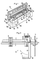
- FIG. 1 the left transport device 1a and in Fig. 2, the right transport device 1b is shown, wherein both transport devices 1a, 1b are guided on a mounting rod 2 and a drive shaft 3, which are themselves set exactly in parallel by side supports 4 and adjusting screws 5.
- the Fastening rod 2 runs through a bore 2a in FIG. 1 and the drive shaft 3, which is square in cross section, runs through a square bushing which is inserted into a bore 3a.
- the drive axle 3 is in this case rotatably supported in a bushing 6 fastened in the side carrier 4.
- the record carrier rests on wings 7 of a guide flap 8 and on a support 9.
- FIGS. 1 and 2 have hinge bearings 11 for their flap components.
- the flap component 10 there consists of a cover flap 12 and, according to FIG. 2, the flap component 10 consists of the guide flap 8. While the guide flap 8 can be swiveled in in the direction 13 for transport or packaging purposes of the printer, the swiveling up and swiveling in of the tractor flap 12 serves to insert the perforated recording medium, ie the perforated paper web. The paper web is inserted with its perforation into the pins 14 of the belt band 15, which is guided in the tractor body 16. The cover flap 12 is then pivoted from the illustrated vertical position into the horizontal position in which it covers the belt band 15.
- the spherical bearings 11 are designed as described below:
- the spherical plain bearings 11 have pivot pins 17 in the form of cut spring steel wire pieces 18.
- the tractor body 16 Provided on the tractor body 16 are the tractor bearings 16a and 16b which are spaced apart in the feed direction 19 and in which the ends 18a and 18b of the spring steel wire piece 18 are mounted.
- the flap component 10 carries two flap component bearings 10a and 10b, each with one Through hole 10c are provided.
- the spring steel wire piece 18 runs in the through bores 10c.
- the flap component bearings 10a and 10b have outer, flat surfaces 10d which are supported on a flat counter surface 16c of the tractor body 16, the spring steel wire piece 18 running slightly curved, that is to say being preloaded. This preload is achieved by an offset of approximately 0.8 mm between the axes of the through bores 10c and the bores 16d in the tractor bearings 16a and 16b.
- At least one tractor bearing 16a or 16b is attached centrally to the tractor body 16 and the relevant flap component 10 has bearings 10a, 10b on its flap component parts.
- the spring steel wire piece 18 is crimped at its ends 18a, 18b in order to avoid falling out of the bearings.
- the flap component 10 is in each case upright, i.e. can be placed vertically and fixed.
- the outer, flat counter surface 16c of the tractor body 16 extends at 90 ° to corresponding surfaces 10d of the flap component bearings 10a, 10b.
- This principle can be used both for the cover flap 12 above the belt band 15 and for the side wing flap 8 for the recording medium and as desired on all flap components of a printer, in particular a matrix printer.
Landscapes
- Handling Of Sheets (AREA)
- Advancing Webs (AREA)
- Hinge Accessories (AREA)
- Macromonomer-Based Addition Polymer (AREA)
- Polymers With Sulfur, Phosphorus Or Metals In The Main Chain (AREA)
- Liquid Developers In Electrophotography (AREA)
- Combination Of More Than One Step In Electrophotography (AREA)
- Character Spaces And Line Spaces In Printers (AREA)
Abstract
Description
Die Erfindung betrifft eine Transportvorrichtung für Drucker, insbesondere für Matrixdrucker, die für die Führung und/oder den Vorschub des Aufzeichnungsträgers mit paarweise angeordneten Traktorvorrichtungen versehen sind, wobei ein Klappenbauteil mittels durch Klappenbauteil-Lager und Traktorlager gebildeten Gelenken befestigt ist.The invention relates to a transport device for printers, in particular for matrix printers, which are provided with paired tractor devices for guiding and / or advancing the record carrier, a flap component being fastened by means of joints formed by flap component bearings and tractor bearings.
Beim Einlegen der Papierbahn in die Stifte des Riemenbandes eines Traktors ist es z.B. erforderlich, die Traktorklappen, d.h. Abdeckungen, die die Papierbahn auf den Stiften halten, wegzuschwenken. Traktorklappen sind daher abschwenkbar gelagert.When inserting the paper web into the pins of the belt strap of a tractor it is e.g. required, the tractor hatches, i.e. Swing covers that hold the paper web on the pins away. Tractor flaps are therefore swivel-mounted.
Eine gattungsgemäß ausgebildete Klappenbauteilbefestigung ist aus der DE-A-1 524 445 bekannt. Die Klappenbauteile, dort sind es die Papierandrückklappen an den Traktoren, werden jeweils mittels vorgespannter Bügelfeder, die an einem scharnierartigen Ansatz der Klappen angreift, in abgeschwenkter Position bzw. am Traktor anliegend gehalten, wobei die Spannung der Bügelfeder durch zwei verschiebbare Spannstücke veränderbar ist.A flap component fastening of the generic type is known from DE-A-1 524 445. The flap components, there are the paper pressure flaps on the tractors, are each held in a pivoted-down position or in contact with the tractor by means of a pretensioned bow spring which engages a hinge-like extension of the flaps, the tension of the bow spring being changeable by two displaceable clamping pieces.
Dieser bekannten Konstruktion haftet der Nachteil an, daß der Aufwand für die Klappenlagerung und die Fixierung der Klappen in der einen oder anderen Position relativ groß und wirtschaftlich kaum vertretbar ist.This known construction has the disadvantage that the effort for the flap mounting and the fixing of the flaps in one position or the other is relatively large and economically unacceptable.
Der Erfindung liegt die Aufgabe zugrunde, für Klappenbauteile an Transportvorrichtungen für Drucker, insbesondere Matrixdruckern, ein einfaches Gelenklager zu schaffen und ebenso eine einfache Feststellvorrichtung für die Klappenpositionen.The invention has for its object to provide a simple spherical bearing for flap components on transport devices for printers, in particular matrix printers, and also a simple locking device for the flap positions.
Diese Aufgabe wird erfindungsgemäß mit den im Kennzeichen des Hauptanspruchs angegebenen Merkmalen gelöst.This object is achieved with the features specified in the characterizing part of the main claim.
Die weitere Ausbildung des Erfindungsgegenstandes geht aus den Unteransprüchen hervor.The further development of the subject matter of the invention emerges from the subclaims.
Der mit der Erfindung erzielte Vorteil ist in der Einfachheit der Konstruktion zu sehen, mit der sowohl ein einfaches Gelenklager als auch eine einfache Feststellvorrichtung für die Klappenbauteile geschaffen worden ist.The advantage achieved with the invention can be seen in the simplicity of the construction, with which both a simple spherical bearing and a simple locking device for the flap components have been created.
Ausführungsbeispiele der Erfindung sind in der Zeichnung dargestellt und werden nachfolgend näher beschrieben.Embodiments of the invention are shown in the drawing and are described in more detail below.
Es zeigen:
- Fig. 1
- den oberen Teil einer Traktorvorrichtung eines Matrixdruckers in perspektivischer Ansicht und
- Fig. 2
- den rechten Teil einer Transportvorrichtung eines Matrixdruckers und einer zusätzlichen Führung für den Aufzeichnungsträger etwa in Transportrichtung des Aufzeichnungsträgers gesehen.
- Fig. 1
- the upper part of a tractor device of a matrix printer in a perspective view and
- Fig. 2
- seen the right part of a transport device of a matrix printer and an additional guide for the record carrier approximately in the transport direction of the record carrier.
Die Transportvorrichtung gemäß Fig. 1 ist paarweise links und rechts von einem hier nicht dargestellten Aufzeichnungsträger angeordnet. In Fig. 1 ist die linke Transportvorrichtung 1a und in Fig. 2 die rechte Transportvorrichtung 1b gezeigt, wobei beide Transportvorrichtungen 1a, 1b auf einer Befestigungsstange 2 und einer Antriebsachse 3 geführt sind, die selbst durch Seitenträger 4 und Einstellschrauben 5 genau parallel eingestellt sind. Die Befestigungsstange 2 verläuft in Fig. 1 durch eine Bohrung 2a und die im Querschnitt quadratische Antriebsachse 3 verläuft durch eine Vierkantbuchse, die in eine Bohrung 3a eingesetzt ist. Die Antriebsachse 3 ist hierbei in einer im Seitenträger 4 befestigte Buchse 6 drehgelagert. Der Aufzeichnungsträger liegt auf Flügeln 7 einer Führungsklappe 8 und auf einer Auflage 9 auf.1 is arranged in pairs to the left and right of a record carrier, not shown here. In Fig. 1, the
Die beiden in den Fig. 1 und 2 dargestellten Ausführungsbeispiele besitzen für ihre Klappenbauteile 10 Gelenklager 11. Gemäß Fig. 1 besteht das dortige Klappenbauteil 10 aus einer Abdeckklappe 12 und gemäß Fig. 2 besteht das dortige Klappenbauteil 10 aus der Führungsklappe 8. Während die Führungsklappe 8 zu Transport- bzw. Verpackungszwecken des Druckers in Richtung 13 einschwenkbar ist, dient das Auf- und Einschwenken der Traktorklappe 12 dem Einlegen des randgelochten Aufzeichnungsträgers, d.h. der randgelochten Papierbahn. Die Papierbahn wird mit ihrer Lochung in die Stifte 14 des Riemenbandes 15 eingelegt, das im Traktorkörper 16 geführt ist. Anschließend wird die Abdeckklappe 12 aus der dargestellten senkrechten Position in die waagerechte Position, in der sie das Riemenband 15 abdeckt, geschwenkt. Die Gelenklager 11 sind wie nachfolgend beschrieben ausgebildet:The two exemplary embodiments shown in FIGS. 1 and 2 have
Die Gelenklager 11 weisen Gelenkzapfen 17 in Form von abgelängten Federstahldrahtstücken 18 auf. Am Traktorkörper 16 sind die in Vorschubrichtung 19 beabstandeten Traktorlager 16a und 16b vorgesehen, in denen die Enden 18a und 18b des Federstahldrahtstückes 18 gelagert sind. Das Klappenbauteil 10 trägt zwei Klappenbauteil-Lager 10a und 10b, die jeweils mit einer Durchgangsbohrung 10c versehen sind. In den Durchgangsbohrungen 10c verläuft das Federstahldrahtstück 18. Die Klappenbauteil-Lager 10a und 10b besitzen äußere, ebene Flächen 10d, die sich auf einer ebenen Gegenfläche 16c des Traktorkörpers 16 aufstützen, wobei das Federstahldrahtstück 18 leicht gekrümmt verläuft, d.h. unter Vorspannung gesetzt ist. Diese Vorspannung wird durch einen Versatz von ca. 0,8 mm zwischen den Achsen der Durchgangsbohrungen 10c und der Bohrungen 16d in den Traktorlagern 16a bzw. 16b erreicht.The
Es werden die beschriebenen Wirkungen auch dadurch erzielt, daß zumindest ein am Traktorkörper 16 mittig befestigtes Traktorlager 16a oder 16b vorgesehen ist und das betreffende Klappenbauteil 10 an seinen Klappenbauteilenden Lager 10a, 10b aufweist.The effects described are also achieved in that at least one tractor bearing 16a or 16b is attached centrally to the
Das Federstahldrahtstück 18 ist an seinen Enden 18a, 18b gequetscht, um ein Herausfallen aus den Lagern zu vermeiden.The spring
Es ist vorteilhaft, wenn das Klappenbauteil 10 jeweils aufrecht, d.h. senkrecht gestellt und fixiert werden kann. Hierzu verläuft die äußere, ebene Gegenfläche 16c des Traktorkörpers 16 unter 90° zu korrespondierenden Flächen 10d der Klappenbauteil-Lager 10a, 10b. Dieses Prinzip kann sowohl für die Abdeckklappe 12 über dem Riemenband 15 als auch für die seitliche Flügelklappe 8 für den Aufzeichnungsträger und beliebig an allen Klappenbauteilen eines Druckers, insbesondere eines Matrixdruckers, angewendet werden.It is advantageous if the
Claims (6)
- A transport device for printers, in particular for matrix printers, which are provided with tractor devices (1a, 1b) arranged in pairs for the guidance and/or the advance of the recording medium, with a flap component (10) being attached by means of hinges formed by flap component bearings (10a, 10b) and tractor bearings (16a, 16b),
characterised in that
a spring steel wire piece (18) which is merely cut to length serves as the pivot pin (17) of the hinges and for fixing a closed or open position of the flap component (10), which piece either extends through through-bores in the flap component bearing (10a, 10b) and is attached by its ends in bores of the tractor bearings (16a, 16b) or extends through through-bores in the tractor bearings (16a, 16b) and is attached by its ends in bores in the flap component bearings (10a, 10b), with the axes of the bores of the tractor bearings (16a, 16b) and the flap component bearings (10a, 10b) being displaced by about 0.8 mm and the spring steel wire piece (18) thus being placed under initial tension by curving it. - A transport device according to Claim 1,
characterised in that in the closed and open positions of the flap component (10) the flap component bearings (10a, 10b) lie with external flat surfaces (10d) on a flat counter-surface (16c) of the tractor body (16) in such a manner that the axes of the bores of the flap component bearings (10a or 10b respectively) in the installed state of the flap component (10) and the bores of the tractor bearings (16a, 16b) deviate from each other. - A transport device according to Claim 1 and 2,
characterised in that the ends (18a, 18b) of the spring steel wire piece (18) are squeezed. - A transport device according to Claim 2,
characterised in that the external flat counter-surface (16c) of the tractor body (16) to the surface (10d) of the flap component bearings (10a, 10b) for closed or open position run at an angle of 90° relative to each other [sic]. - A transport device according to Claims 1 to 4,
characterised in that the flap component (10) is designed as a cover flap (12) for the belt strip (15) of the tractor device (1a). - A transport device according to Claims 1 to 4,
characterised in that the flap component (10) is designed as a lateral guide flap (8) for the recording medium.
Priority Applications (1)
| Application Number | Priority Date | Filing Date | Title |
|---|---|---|---|
| AT85730019T ATE62627T1 (en) | 1984-04-03 | 1985-02-06 | TRANSPORT DEVICE FOR PRINTERS, ESPECIALLY FOR MATRIX PRINTERS. |
Applications Claiming Priority (2)
| Application Number | Priority Date | Filing Date | Title |
|---|---|---|---|
| DE3412852 | 1984-04-03 | ||
| DE3412852A DE3412852C2 (en) | 1984-04-03 | 1984-04-03 | Transport device for printers, in particular for matrix printers |
Publications (3)
| Publication Number | Publication Date |
|---|---|
| EP0157724A2 EP0157724A2 (en) | 1985-10-09 |
| EP0157724A3 EP0157724A3 (en) | 1988-06-08 |
| EP0157724B1 true EP0157724B1 (en) | 1991-04-17 |
Family
ID=6232780
Family Applications (1)
| Application Number | Title | Priority Date | Filing Date |
|---|---|---|---|
| EP85730019A Expired - Lifetime EP0157724B1 (en) | 1984-04-03 | 1985-02-06 | Transport device for a printer, especially for a matrix printer |
Country Status (5)
| Country | Link |
|---|---|
| US (1) | US4650358A (en) |
| EP (1) | EP0157724B1 (en) |
| JP (1) | JPS60212366A (en) |
| AT (1) | ATE62627T1 (en) |
| DE (2) | DE3412852C2 (en) |
Families Citing this family (11)
| Publication number | Priority date | Publication date | Assignee | Title |
|---|---|---|---|---|
| US4758107A (en) * | 1986-05-02 | 1988-07-19 | Sakase Kagaku Kogyo Kabushiki Kaisha | Web feed tractor for printer |
| US4780013A (en) * | 1986-05-02 | 1988-10-25 | Sakase Kagaku Kogyo Kabushiki Kaisha | Web feed tractor for printer |
| JPS6399969A (en) * | 1986-10-17 | 1988-05-02 | Canon Inc | Recording device pin feed device |
| DE8711771U1 (en) * | 1987-08-31 | 1987-10-29 | Nixdorf Computer Ag, 4790 Paderborn | Transport device for transporting a recording medium through a printer |
| US4817842A (en) * | 1988-01-29 | 1989-04-04 | International Business Machines Corporation | Door and spring assembly for a paper feed mechanism |
| EP0352397B1 (en) * | 1988-07-26 | 1993-01-07 | MANNESMANN Aktiengesellschaft | Speed control device for pulse width-modulated electric motors, especially for direct current motors |
| US4955520A (en) * | 1989-03-24 | 1990-09-11 | Precision Handling Devices, Inc. | Web feed device having an improved lid mechanism |
| US5488467A (en) * | 1994-06-24 | 1996-01-30 | Rjs, Inc. | Laser printer paper handling system |
| PT2537900E (en) | 2011-06-21 | 2016-01-22 | Omya Int Ag | Process for the production of precipitated calcium carbonate |
| CN109262070B (en) * | 2018-11-08 | 2020-04-17 | 温州普睿达机械科技有限公司 | Pipeline processing cutting spouts a yard all-in-one |
| CN114715707B (en) * | 2022-03-31 | 2023-01-03 | 先之科半导体科技(东莞)有限公司 | Wafer material belt transmission structure convenient to adjust |
Family Cites Families (14)
| Publication number | Priority date | Publication date | Assignee | Title |
|---|---|---|---|---|
| US2342477A (en) * | 1941-08-08 | 1944-02-22 | Waterbury Button Company | Plastic hinge cap |
| US2442873A (en) * | 1944-04-28 | 1948-06-08 | Trig Corp | Molded plastic receptacle hinge |
| US2797434A (en) * | 1953-12-23 | 1957-07-02 | Chrysler Corp | Hood or deck lid hinge |
| US2707800A (en) * | 1954-08-16 | 1955-05-10 | Popper Emil | Spring hinge for bracelets, watch bands, and the like |
| US2987332A (en) * | 1958-11-17 | 1961-06-06 | Bonmartini Glovanni | Resilient torque-transmitting hinge structure |
| US3388420A (en) * | 1966-09-15 | 1968-06-18 | Gen Motors Corp | Integral hinge and hinge bias structure |
| DE1524445B2 (en) * | 1966-12-24 | 1973-02-15 | IBM Deutschland, 7000 Stuttgart | DEVICE FOR THE INDEPENDENT TRANSPORTATION OF TWO WAYS OF PAPER |
| US3545034A (en) * | 1969-01-31 | 1970-12-08 | Gen Motors Corp | Over-center door hinge |
| JPS552043A (en) * | 1978-06-22 | 1980-01-09 | Oki Electric Ind Co Ltd | Fixing system for continuous supply device |
| DE3036642A1 (en) * | 1980-09-29 | 1982-05-13 | Philips Patentverwaltung Gmbh, 2000 Hamburg | TRANSPORT DEVICE FOR PAPER RAILS IN BOOKING MACHINES |
| IT1135127B (en) * | 1981-01-22 | 1986-08-20 | Honeywell Inf Systems | PAPER TRANSPORTATION MECHANISM FOR PRINTER |
| FR2499618A1 (en) * | 1981-02-06 | 1982-08-13 | Lucas Noel | Settable hinge for door - incorporates spring biassed cam which holds door open in predetermined positions |
| US4390002A (en) * | 1981-08-14 | 1983-06-28 | Unarco Industries, Inc. | Hinge for cover of kettle cooker |
| US4493680A (en) * | 1982-12-02 | 1985-01-15 | Florkey's Conveyor Service, Inc. | Wear compensating link pin |
-
1984
- 1984-04-03 DE DE3412852A patent/DE3412852C2/en not_active Expired
-
1985
- 1985-02-06 AT AT85730019T patent/ATE62627T1/en not_active IP Right Cessation
- 1985-02-06 DE DE8585730019T patent/DE3582511D1/en not_active Expired - Fee Related
- 1985-02-06 EP EP85730019A patent/EP0157724B1/en not_active Expired - Lifetime
- 1985-02-26 JP JP60037346A patent/JPS60212366A/en active Granted
- 1985-04-02 US US06/719,241 patent/US4650358A/en not_active Expired - Fee Related
Also Published As
| Publication number | Publication date |
|---|---|
| EP0157724A2 (en) | 1985-10-09 |
| DE3582511D1 (en) | 1991-05-23 |
| DE3412852C2 (en) | 1986-07-17 |
| ATE62627T1 (en) | 1991-05-15 |
| JPH0431314B2 (en) | 1992-05-26 |
| US4650358A (en) | 1987-03-17 |
| JPS60212366A (en) | 1985-10-24 |
| EP0157724A3 (en) | 1988-06-08 |
| DE3412852A1 (en) | 1985-10-03 |
Similar Documents
| Publication | Publication Date | Title |
|---|---|---|
| DE2840053C2 (en) | Hinge for a hood of a motor vehicle | |
| DE60207041T2 (en) | GUIDANCE UNIT FOR CONVEYOR BELT | |
| DE3412852C2 (en) | Transport device for printers, in particular for matrix printers | |
| AT500109A1 (en) | TRANSFER DEVICE FOR THE SIDE EXTINGUISHING OF SUPPLIES AND A CONVEYOR DEVICE | |
| DE3314628A1 (en) | FRICTION FEED PAPER HANDLING DEVICE | |
| DE2540357C3 (en) | Device for arranging a RoUe | |
| DE3342105C2 (en) | ||
| EP0223186A2 (en) | Adjustable door or window hinge | |
| DE2110836B2 (en) | Device for transporting book blocks | |
| EP3712364B1 (en) | Hinge for doors, windows and furniture | |
| DE102023108536B4 (en) | Air guide device of a motor vehicle body with a flexible air guide element | |
| DE4123840A1 (en) | DEVICE FOR A TENSION CLAMP ASSEMBLY FOR CONTINUOUSLY VARIABLE DIVISION | |
| EP0061766A1 (en) | Suspension for the swivel-mounted tape drive motor of a magnetic cassette tape recorder | |
| DE2545694C2 (en) | Sliding door for vehicles | |
| DE9006554U1 (en) | Longitudinally movable mounting carriage mounted on a guide tube | |
| EP1848847B1 (en) | Top cylinder carrier for drafting systems in spinning machines. | |
| DE2559494C3 (en) | Ribbon cassette for typewriters and similar machines | |
| DE2339623C3 (en) | Adjustable door hanger | |
| DE3136192C2 (en) | Paper guide for printer | |
| DE2758721A1 (en) | Vertical friction surface pair in leaf spring assembly - is formed by spring blade side surfaces, and spring dog jaw inner surface | |
| DE2727585C2 (en) | Adjustable handlebar pivot bearing for bottom-hung windows or doors | |
| DE29716897U1 (en) | Welding head for a strapping machine | |
| DE19854739C1 (en) | Support roller assembly for building movable door or window leaf has adjusting screw engaging semi-circular notch in cantilever | |
| DE602004011543T2 (en) | Device for detecting an open window or door shutter | |
| DE19525963C2 (en) | Belt buckle |
Legal Events
| Date | Code | Title | Description |
|---|---|---|---|
| PUAI | Public reference made under article 153(3) epc to a published international application that has entered the european phase |
Free format text: ORIGINAL CODE: 0009012 |
|
| AK | Designated contracting states |
Designated state(s): AT BE CH DE FR GB IT LI NL |
|
| 17P | Request for examination filed |
Effective date: 19850907 |
|
| PUAL | Search report despatched |
Free format text: ORIGINAL CODE: 0009013 |
|
| AK | Designated contracting states |
Kind code of ref document: A3 Designated state(s): AT BE CH DE FR GB IT LI NL |
|
| 17Q | First examination report despatched |
Effective date: 19891013 |
|
| GRAA | (expected) grant |
Free format text: ORIGINAL CODE: 0009210 |
|
| AK | Designated contracting states |
Kind code of ref document: B1 Designated state(s): AT BE CH DE FR GB IT LI NL |
|
| REF | Corresponds to: |
Ref document number: 62627 Country of ref document: AT Date of ref document: 19910515 Kind code of ref document: T |
|
| ITF | It: translation for a ep patent filed | ||
| ET | Fr: translation filed | ||
| REF | Corresponds to: |
Ref document number: 3582511 Country of ref document: DE Date of ref document: 19910523 |
|
| GBT | Gb: translation of ep patent filed (gb section 77(6)(a)/1977) | ||
| PG25 | Lapsed in a contracting state [announced via postgrant information from national office to epo] |
Ref country code: AT Effective date: 19920206 |
|
| PLBE | No opposition filed within time limit |
Free format text: ORIGINAL CODE: 0009261 |
|
| STAA | Information on the status of an ep patent application or granted ep patent |
Free format text: STATUS: NO OPPOSITION FILED WITHIN TIME LIMIT |
|
| PG25 | Lapsed in a contracting state [announced via postgrant information from national office to epo] |
Ref country code: BE Effective date: 19920228 |
|
| PG25 | Lapsed in a contracting state [announced via postgrant information from national office to epo] |
Ref country code: LI Effective date: 19920229 Ref country code: CH Effective date: 19920229 |
|
| 26N | No opposition filed | ||
| BERE | Be: lapsed |
Owner name: MANNESMANN A.G. Effective date: 19920228 |
|
| PG25 | Lapsed in a contracting state [announced via postgrant information from national office to epo] |
Ref country code: NL Effective date: 19920901 |
|
| NLV4 | Nl: lapsed or anulled due to non-payment of the annual fee | ||
| REG | Reference to a national code |
Ref country code: CH Ref legal event code: PL |
|
| PGFP | Annual fee paid to national office [announced via postgrant information from national office to epo] |
Ref country code: GB Payment date: 19930113 Year of fee payment: 9 |
|
| PGFP | Annual fee paid to national office [announced via postgrant information from national office to epo] |
Ref country code: FR Payment date: 19930120 Year of fee payment: 9 |
|
| PGFP | Annual fee paid to national office [announced via postgrant information from national office to epo] |
Ref country code: DE Payment date: 19930322 Year of fee payment: 9 |
|
| PG25 | Lapsed in a contracting state [announced via postgrant information from national office to epo] |
Ref country code: GB Effective date: 19940206 |
|
| GBPC | Gb: european patent ceased through non-payment of renewal fee |
Effective date: 19940206 |
|
| PG25 | Lapsed in a contracting state [announced via postgrant information from national office to epo] |
Ref country code: FR Effective date: 19941031 |
|
| PG25 | Lapsed in a contracting state [announced via postgrant information from national office to epo] |
Ref country code: DE Effective date: 19941101 |
|
| REG | Reference to a national code |
Ref country code: FR Ref legal event code: ST |