EP0157805B1 - Procede, installation et/ou dispositif de preparation de battitures enduites d'huile ou de materiaux similaires - Google Patents
Procede, installation et/ou dispositif de preparation de battitures enduites d'huile ou de materiaux similaires Download PDFInfo
- Publication number
- EP0157805B1 EP0157805B1 EP19840903430 EP84903430A EP0157805B1 EP 0157805 B1 EP0157805 B1 EP 0157805B1 EP 19840903430 EP19840903430 EP 19840903430 EP 84903430 A EP84903430 A EP 84903430A EP 0157805 B1 EP0157805 B1 EP 0157805B1
- Authority
- EP
- European Patent Office
- Prior art keywords
- washing
- drum
- lye
- washed
- oil
- Prior art date
- Legal status (The legal status is an assumption and is not a legal conclusion. Google has not performed a legal analysis and makes no representation as to the accuracy of the status listed.)
- Expired
Links
- 238000000034 method Methods 0.000 title claims abstract description 32
- 239000000463 material Substances 0.000 title claims abstract description 24
- 238000005406 washing Methods 0.000 claims abstract description 62
- HEMHJVSKTPXQMS-UHFFFAOYSA-M sodium hydroxide Inorganic materials [OH-].[Na+] HEMHJVSKTPXQMS-UHFFFAOYSA-M 0.000 claims abstract description 57
- 235000011121 sodium hydroxide Nutrition 0.000 claims abstract description 27
- 239000007788 liquid Substances 0.000 claims abstract description 7
- XLYOFNOQVPJJNP-UHFFFAOYSA-N water Substances O XLYOFNOQVPJJNP-UHFFFAOYSA-N 0.000 claims abstract description 7
- 238000004519 manufacturing process Methods 0.000 claims abstract description 4
- 239000002002 slurry Substances 0.000 claims description 3
- 238000012360 testing method Methods 0.000 claims description 3
- 238000006243 chemical reaction Methods 0.000 claims description 2
- 238000010276 construction Methods 0.000 claims description 2
- 239000000725 suspension Substances 0.000 claims description 2
- 239000004111 Potassium silicate Substances 0.000 claims 1
- 239000004115 Sodium Silicate Substances 0.000 claims 1
- 230000003139 buffering effect Effects 0.000 claims 1
- 230000002093 peripheral effect Effects 0.000 claims 1
- 229910052913 potassium silicate Inorganic materials 0.000 claims 1
- NNHHDJVEYQHLHG-UHFFFAOYSA-N potassium silicate Chemical compound [K+].[K+].[O-][Si]([O-])=O NNHHDJVEYQHLHG-UHFFFAOYSA-N 0.000 claims 1
- 235000019353 potassium silicate Nutrition 0.000 claims 1
- 229910052911 sodium silicate Inorganic materials 0.000 claims 1
- NTHWMYGWWRZVTN-UHFFFAOYSA-N sodium silicate Chemical compound [Na+].[Na+].[O-][Si]([O-])=O NTHWMYGWWRZVTN-UHFFFAOYSA-N 0.000 claims 1
- 238000003801 milling Methods 0.000 abstract 3
- 239000012770 industrial material Substances 0.000 abstract 1
- 239000003921 oil Substances 0.000 description 30
- 239000003513 alkali Substances 0.000 description 7
- 229910052751 metal Inorganic materials 0.000 description 6
- 239000002184 metal Substances 0.000 description 6
- 239000010802 sludge Substances 0.000 description 6
- 241000446313 Lamella Species 0.000 description 5
- 229910052782 aluminium Inorganic materials 0.000 description 5
- XAGFODPZIPBFFR-UHFFFAOYSA-N aluminium Chemical compound [Al] XAGFODPZIPBFFR-UHFFFAOYSA-N 0.000 description 5
- 238000004140 cleaning Methods 0.000 description 3
- 239000011248 coating agent Substances 0.000 description 3
- 238000000576 coating method Methods 0.000 description 3
- 239000012530 fluid Substances 0.000 description 3
- 230000001590 oxidative effect Effects 0.000 description 3
- 239000002244 precipitate Substances 0.000 description 3
- 238000001556 precipitation Methods 0.000 description 3
- XEEYBQQBJWHFJM-UHFFFAOYSA-N Iron Chemical compound [Fe] XEEYBQQBJWHFJM-UHFFFAOYSA-N 0.000 description 2
- QAOWNCQODCNURD-UHFFFAOYSA-N Sulfuric acid Chemical compound OS(O)(=O)=O QAOWNCQODCNURD-UHFFFAOYSA-N 0.000 description 2
- 239000000571 coke Substances 0.000 description 2
- 239000002826 coolant Substances 0.000 description 2
- 238000011049 filling Methods 0.000 description 2
- 239000002245 particle Substances 0.000 description 2
- 239000000047 product Substances 0.000 description 2
- 230000000630 rising effect Effects 0.000 description 2
- 238000000926 separation method Methods 0.000 description 2
- 239000002689 soil Substances 0.000 description 2
- 239000007787 solid Substances 0.000 description 2
- 239000003795 chemical substances by application Substances 0.000 description 1
- 238000002485 combustion reaction Methods 0.000 description 1
- 239000002131 composite material Substances 0.000 description 1
- 239000000356 contaminant Substances 0.000 description 1
- 239000010779 crude oil Substances 0.000 description 1
- 238000005520 cutting process Methods 0.000 description 1
- 230000007547 defect Effects 0.000 description 1
- 238000011161 development Methods 0.000 description 1
- 230000018109 developmental process Effects 0.000 description 1
- 238000010586 diagram Methods 0.000 description 1
- 239000012153 distilled water Substances 0.000 description 1
- 229910000514 dolomite Inorganic materials 0.000 description 1
- 239000010459 dolomite Substances 0.000 description 1
- 238000001704 evaporation Methods 0.000 description 1
- 230000008020 evaporation Effects 0.000 description 1
- 238000004880 explosion Methods 0.000 description 1
- 239000004744 fabric Substances 0.000 description 1
- 239000006260 foam Substances 0.000 description 1
- 229910052742 iron Inorganic materials 0.000 description 1
- 239000000314 lubricant Substances 0.000 description 1
- 239000010721 machine oil Substances 0.000 description 1
- 239000011268 mixed slurry Substances 0.000 description 1
- 238000002156 mixing Methods 0.000 description 1
- 238000000465 moulding Methods 0.000 description 1
- 239000002736 nonionic surfactant Substances 0.000 description 1
- 239000003208 petroleum Substances 0.000 description 1
- 238000012545 processing Methods 0.000 description 1
- 238000005096 rolling process Methods 0.000 description 1
- 150000004760 silicates Chemical class 0.000 description 1
- 239000012257 stirred material Substances 0.000 description 1
- 239000000126 substance Substances 0.000 description 1
- 238000012546 transfer Methods 0.000 description 1
- 238000011144 upstream manufacturing Methods 0.000 description 1
Images

Classifications
-
- C—CHEMISTRY; METALLURGY
- C22—METALLURGY; FERROUS OR NON-FERROUS ALLOYS; TREATMENT OF ALLOYS OR NON-FERROUS METALS
- C22B—PRODUCTION AND REFINING OF METALS; PRETREATMENT OF RAW MATERIALS
- C22B1/00—Preliminary treatment of ores or scrap
- C22B1/005—Preliminary treatment of scrap
-
- Y—GENERAL TAGGING OF NEW TECHNOLOGICAL DEVELOPMENTS; GENERAL TAGGING OF CROSS-SECTIONAL TECHNOLOGIES SPANNING OVER SEVERAL SECTIONS OF THE IPC; TECHNICAL SUBJECTS COVERED BY FORMER USPC CROSS-REFERENCE ART COLLECTIONS [XRACs] AND DIGESTS
- Y02—TECHNOLOGIES OR APPLICATIONS FOR MITIGATION OR ADAPTATION AGAINST CLIMATE CHANGE
- Y02P—CLIMATE CHANGE MITIGATION TECHNOLOGIES IN THE PRODUCTION OR PROCESSING OF GOODS
- Y02P10/00—Technologies related to metal processing
- Y02P10/20—Recycling
-
- Y—GENERAL TAGGING OF NEW TECHNOLOGICAL DEVELOPMENTS; GENERAL TAGGING OF CROSS-SECTIONAL TECHNOLOGIES SPANNING OVER SEVERAL SECTIONS OF THE IPC; TECHNICAL SUBJECTS COVERED BY FORMER USPC CROSS-REFERENCE ART COLLECTIONS [XRACs] AND DIGESTS
- Y10—TECHNICAL SUBJECTS COVERED BY FORMER USPC
- Y10S—TECHNICAL SUBJECTS COVERED BY FORMER USPC CROSS-REFERENCE ART COLLECTIONS [XRACs] AND DIGESTS
- Y10S210/00—Liquid purification or separation
- Y10S210/918—Miscellaneous specific techniques
- Y10S210/922—Oil spill cleanup, e.g. bacterial
- Y10S210/923—Oil spill cleanup, e.g. bacterial using mechanical means, e.g. skimmers, pump
Definitions
- the invention relates to a method for processing oiled piles, mill scale or the like. Materials that are obtained as laundry in industrial processes such as mill scale.
- the mill scale must be de-oiled before use, for which there are the following methods according to the prior art.
- the oily mill scale is mixed with unoiled mill scale so that the total proportion of oil drops below the harmful level. Since a true mixing of oily and non-oily scale is technically hardly feasible, this process always leads to oil pockets and thus to the defects already described above.
- the oily mill scale can also u. a. be placed in a downstream coke battery.
- the presence of iron makes the sulfuric acid that forms so aggressive that the pipe systems that come into contact with it are eroded for a short time.
- manufacturers of coke oven plants refuse any guarantee for the latter if the use of oiled mill scale is intended.
- the inventor has set himself the goal of designing a method of the type mentioned at the outset in such a way that de-oiling of the industrial laundry, in particular the mill scale, is possible.
- This method and the system and / or devices created for it should also be used for the treatment of oily aluminum chips or the like.
- the mill scale or the corresponding laundry - more or less in a sludge-like consistency - is introduced into a washing drum and washed there in a washing liquor mixed with 2% caustic soda at about 50 ° C. and higher temperature.
- the slats which are inclined on the inner surface of the closed drum wall, are arranged, of which several run on a helix, ie form a helix.
- these slats are inclined in two planes, the size of the two inclination angles depending on the slip behavior of the material used and on the desired gradient of this helix.
- the default is such a tendency that the metal chips to be cleaned before lifting via the SPI - gel the wash down of the slat slide and underneath of the lamella are collected. This washing below the alkali level is only necessary for strongly oxidizing materials - otherwise it can also be raised above the alkali level.
- washing is carried out in the washing drum at a higher temperature; lower temperatures lead to significantly poorer deoiling.
- the washing liquor discharged from the washing drum and loaded with oil is advantageously conducted in a decanter and deoiled by means of a separator.
- the liquor is then passed back into the washing drum via a heat exchanger and / or an evaporator - producing distilled water.
- test results achieved are sufficient to be able to offer a reusable scale.
- part of the fine mill scale is removed with the lye and only separated from the lye in the decanter.
- a mud-like precipitate is obtained with the decanter.
- This sludge is advantageously stirred into lye, that is treated in an agitator and at the same time blow the stirred material with air.
- an agitator tank on the bottom is equipped with nozzles, which can optionally be acted upon by lye or air.
- the sludge supply to the agitator tank can be interrupted and the agitator can be switched off.
- the air gassing is maintained according to the invention so that the oil is entrained with the rising air bubbles - accelerated deoiling takes place. After a while, the air supply is also switched off and the oil is sucked off the surface.
- Sludge deposited at the bottom of the agitator tank is whirled up again using the agitator until no more oil rises.
- the sludge is whirled up to reduce the starting torque of the agitator.
- the oil that has risen is sucked off again. This process is controlled depending on the oil content.
- the discharge from the decanter is largely deoiled, it is dewatered according to the invention, together with the laundry from the washing drum.
- the method according to the invention and a system suitable for it are - above all for mill scale - particularly suitable for de-oiling metal chips or dolomite, as well as for de-oiling ends.
- the prior art includes a plant according to GB-A-2 012 815, in which a coating, for example a metal coating, is to be peeled off from shredded, shredded, tinned bushings.
- a drum is arranged to be rotatable about an oblique axis and circulates the parts while the drum rotates in one direction. When rotating in the opposite direction, the parts are removed.
- An electrochemical element is connected to the fluid outlet to recover the coating material by means of galvanic precipitation.
- Lifting vanes are arranged inside the drum.
- the prior art includes a plant according to US-A-4,336,136 in which soil which is contaminated by heavy crude oil, refined petroleum and / or chemical products which come from similar sources is to be reprocessed.
- a mixer is provided which heats the soil with a liquid and generates a heated mixed slurry.
- the slurry is then treated several times to achieve separation of the oil particles from the fine slurry particles.
- a kiln in the form of a drum is also used, which has steam pipes inside which sprinkle the sludge, as well as offset baffles that protrude inwards from the inside wall of the drum.
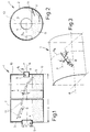
- a washing drum 1 with a diameter d of 150 cm in the selected example and a length n of 500 cm has, in an end wall 3 which closes the cylindrical drum wall 2, a feed device 4 for laundry S in the form of oiled mill scale.
- the diameter e of the feed device 4 is approximately 60 cm, whereas the diameter t of an inlet 6 provided in the opposite end wall 5 for a wash liquor L is approximately 30 cm.
- slats 11 are provided, the surface F of which includes an inclination angle w t or w 2 on the one hand to a circumferential contour U k and on the other hand to a wall line P running parallel to a drum axis A (FIG. 3).
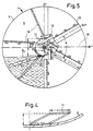
- the length C of the slats 11 measures approximately 150 mm, their width f then 80 mm. 4 illustrates the projection height i (e.g. 40 mm).
- a plurality of lamellae 11 determine a helical line G on an imaginary line, that is to say they form a composite spiral. For reasons of clarity, only a few of the slats 11 are shown in the drawing - however, several coils are present in the washing drum 1.
- the slats 11 are adjustable with respect to the angles W 1 and W 2 in order to be able to adapt the shape of that helix to the respective laundry.
- the washing drum 1 is used to clean oiled piles, such as oiled roller scale or aluminum chips, the oil film of which is washed out on the surface of the metal in the alkali L.
- the liquor L contained in the laundry S is designated by Q.
- the slats 11 are preferred attached in such a way that part of the items to be washed falls back on its conveying path to the underlying - ie upstream - lamella 11, thereby extending the conveying path.
- the laundry S can be raised above the suds level Q s , and it falls depending on the inclination of the surface F onto the next spiral underneath.
- the transfer from a lamella 11 to the one below it should be carried out below the alkali level Q s .
- the dimensions of the angles of inclination w 1 and w 2 depend on the one hand on the angle of rubble of the items to be cleaned S and on the other hand on the angle of inclination z of the helix. Their slope in turn depends on the length n of the washing drum 1 and its number of revolutions, taking into account the dwell time of the laundry item L in the liquor Q required for cleaning.
- the degree of filling of the washing drum 1 is also important.
- the size of the surface F of the lamella 11 is 15 cm ⁇ 8 cm ⁇ 5 cm in the selected exemplary embodiment, the lamella 11 are shown exaggerated in the drawing.
- FIG. 5 there is a particularly preferred embodiment with a discharge channel 15 and discharge webs 16 which form tangents to a construction circle 17; the diameter g of which lies between the diameter h of the discharge opening 14 and the diameter of the drum axis 9. Thanks to this requirement, the laundry item S only slides above the horizontal line H from the discharge web 16.
- a nozzle assembly 40 is symbolically shown below the lye level Q s , from whose bores 41 the wash liquor is sprayed against the end wall 5. Thanks to the pressure of the wash liquor supplied, a zone free of residues is generated at the mirror Q s in the wash liquor already present, through which the laundry S can be lifted without interference.
- the alkaline wash liquor Q mainly has silicates and nonionic surfactants and, according to FIG. 6, is led from a first wash drum 1 a to a decanter 20, the overflow Q 1 of which passes into a separator 21 and from there through a heat exchanger 22 as liquor L. Washing drum 1 a is recycled. Instead of or in addition to the heat exchanger 22, an evaporation station neglected in the drawing can be provided.
- the number of revolutions of the decanter 20 is chosen according to the invention so that the adhesion of the oil to the laundry 5 - that is to say on the surface of the mill scale - is greater than the centrifugal force, so that the oil is largely discharged with the solid as decanter precipitation B.
- the items to be washed S after the first washing drum 1 a, are guided via a drainage channel 25 to a second washing drum 1 b , which in turn is connected to an alkali circuit as described for the washing drum 1 a .
- the laundry S 2 passes through the washing drum 1 b again through a drainage channel 25 - or a chamber filter press 26 - and then passes into a washing drum 1 c operated with clear water. A liquid exchange is carried out with this clear water, so that 1 c cleaned product from the washing drum Z exits.
- a mud-like material B is placed in the laundry; this is the residue from the decanter precipitation B, which has been largely freed of the oil drawn off at the oil drain 31 in a stirrer 30.
- air nozzles 34 are provided in the bottom area, which are optionally acted upon with wash liquor or air.
- the air supply via the air nozzles 34 is also interrupted, so that the oil can be drawn off from the suspension surface in the container 33.
- the sludge deposited at the bottom of the container 33 is whirled up again by means of the agitator 30. If the agitator 30 is in operation, the alkali supply is switched off and air is blown in again. The oil that has risen is sucked off again. This process is controlled depending on the oil content. If the decanter precipitate B to be processed here is largely deoiled, it is fed into a chamber filter press 26 together with the laundry S from the second washing drum 1 b .
- the oil obtained at the oil drain 31 is processed so that it can be sold again. This is essentially a separation of the oil from residual lye and suspended solids.
Landscapes
- Engineering & Computer Science (AREA)
- Chemical & Material Sciences (AREA)
- Manufacturing & Machinery (AREA)
- Geochemistry & Mineralogy (AREA)
- Geology (AREA)
- General Life Sciences & Earth Sciences (AREA)
- Life Sciences & Earth Sciences (AREA)
- Environmental & Geological Engineering (AREA)
- Materials Engineering (AREA)
- Mechanical Engineering (AREA)
- Metallurgy (AREA)
- Organic Chemistry (AREA)
- Cleaning And De-Greasing Of Metallic Materials By Chemical Methods (AREA)
- Detergent Compositions (AREA)
Abstract
Claims (16)
- I. Procédé pour le traitement de déblais salis par d'huile, battitures ou de matériaux semblables qui est produit lors des processus industriels en tant que lavée
caractérisé en ce que
le matériel sali par d'huile est envoyé dans un tambour laveur où il est lavé à contre-courant dans une lessive de 10 à 14 pH, cette lavée étant en même temps soulevée à la paroi du tambour par des surfaces d'appui. - 2. Procédé selon la revendication 1 caractérisé en ce que la lessive est ajustée de 12 à 14 pH.
- 3. Procédé selon la revendication 1 ou 2 caractérisé en ce que la lessive est mélangée avec environ 2 % de soude caustique et/ou que le lavage se fait à environ 50°C ou à une température plus élevée.
- 4. Procédé selon la revendication 1 ou 2 caractérisé en ce que est utilisée une lessive sans phosphate et sans carbone.
- 5. Procédé selon une des revendications 1 à 4 caractérisé en ce que lors du lavage ou avant la répétition du lavage se fait un tamponnage avec potassium silicié ou avec silicate de sodium jusqu'à ce qu'il n'y a pas de réaction avec la lessive.
- 6. Procédé selon une des revendications 1 à 5 caractérisé en ce que après le lavage ou la répétition du lavage est fait une diffusion de liquides avec de l'eau pure et/ou que la lavée est déshydratée entre les procédés de lavage.
- 7. Procédé selon une des revendications 1 à 6 caractérisé en ce que la lessive est amenée derrière le tambour à travers d'un appareil à décanter et que une partie des matières en suspension fines est séparée de la lessive qui ensuite est amenée - avant le retour dans le tambour - à un séparateur pour être déshuilée et que d'autre côté de l'appareil à décanter sort de l'huile avec le matériel d'essai comme dépot décanter.
- 8. Procédé selon la revendication 7 caractérisé en ce que avant le retour au tambour la lessive est ajustée à sa concentration initiale et mise sur la température de lavage en traversant de préférance un échangeur thérmique et/ou un vaporisateur.
- 9. Procédé selon une des revendications 7 ou 8 caractérisé en ce que le dépôt décanter est délayer dans de la lessive.
- 10. Procédé selon une des revendications 7 à 9 caractérisé en ce que après être déshuilé le dépôt décanter est déshydraté avec la lavée sortie du tambour.
- 11. Procédé selon une des revendications 7 à 10 caractérisé en ce que le dépôt décanter est amené à un mélangeur dont le récipient (33) possède vers le fond des buses d'air qui sont injectées en option avec de la lessive ou de l'air, que l'huile est décantée de la surface de suspension dans le récipient et que la boue déposée au fond du récipient du mélangeur est de nouveau soulevée en tourbillons.
- 12. Procédé selon une des revendications précédentes caractérisé en ce que lors de l'utilisation de trois tambours la lessive est sortie du premier tambour et amenée à un appareil à décanter duquel d'un côté la surverse de la lessive est amenée à un séparateur pour être déshuilée et ensuite retournée dans le premier tambour et du quel d'autre côté le dépôt décanter est amené à un mélangeur, que la lavée sortie du premier tambour est amenée au deuxième tambour par l'intermédiaire d'une tranchée d'eau, ce deuxième tambour étant raccordé de sa part à un circuit de lessive semblable à celui du premier tambour, que la décharge du mélangeur est amenée avec la lavée sortie du deuxième tambour à un filtre-presse à chambres, ou à une tranchée d'eau et ensuite au troisième tambour qui fonctionne avec de l'eau pure et duquel est sortie la lavée purifiée.
- 13. Procédé selon une des revendications 1 à 12 caractérisé en ce que les surfaces d'appui à la paroi de tambour par lesquelles la lavée est soulevée sont des lamelles placées de manière inclinée à la surface intérieure de la paroi du tambour dont plusieurs se trouvent sur une hélice et que de préférance la surface de la lamelle forme des angles d'inclinaison d'un côté avec le contour circonférentiel de la paroi du tambour (2) et d'autre côté avec une parallèle à l'axe du tambour dans la paroi du tambour.
- 14. Procédé selon la revendication 13 caractérisé en ce que au moins un des angles d'inclinaison (W1' w2) se monte à 30° et/ou que les angles d'inclinaison (wi, w2) des lamelles dans le tambour sont réglables.
- 15. Procédé selon une des revendications 1 à 14 caractérisé en ce que la lavée est soulevée à la paroi du tambour par des traverses supplémentaires (12, 16) qui sont attribuées à la paroi frontale de décharge du tambour qui se trouvent au-dessus du point marginal plus bas de l'ouverture de décharge (14) de manière inclinée vers celle-ci et qui sont le cas échéant, des tangentes à un cercle de construction (17) autour de l'axe du tambour dont le diamètre (g) est plus grand que celui de l'arbre de tambour et inférieur à celui de l'ouverture de décharge (14) (fig 5, à gauche).
- 16. Procédé selon une des revendications précédentes en particulier selon la revendication 15 caractérisé en ce que le jet d'au moins une amenée de lessive (40) dans le tambour est dirigé contre la paroi frontale de décharge (5) de celle-ci qui est amené de préférance au-dessous du niveau de la lessive (Qs) au côté de l'arbre avec des traverses tournant en haut (16).
Applications Claiming Priority (4)
| Application Number | Priority Date | Filing Date | Title |
|---|---|---|---|
| DE8325846U | 1983-09-08 | ||
| DE19838325846 DE8325846U1 (de) | 1983-09-08 | 1983-09-08 | Waschtrommel zur aufnahme einer reinigungslauge |
| DE3422545 | 1984-06-18 | ||
| DE3422545 | 1984-06-18 |
Publications (2)
| Publication Number | Publication Date |
|---|---|
| EP0157805A1 EP0157805A1 (fr) | 1985-10-16 |
| EP0157805B1 true EP0157805B1 (fr) | 1989-08-02 |
Family
ID=25822228
Family Applications (1)
| Application Number | Title | Priority Date | Filing Date |
|---|---|---|---|
| EP19840903430 Expired EP0157805B1 (fr) | 1983-09-08 | 1984-09-06 | Procede, installation et/ou dispositif de preparation de battitures enduites d'huile ou de materiaux similaires |
Country Status (5)
| Country | Link |
|---|---|
| US (1) | US4988391A (fr) |
| EP (1) | EP0157805B1 (fr) |
| DE (1) | DE3479228D1 (fr) |
| IT (1) | IT1181216B (fr) |
| WO (1) | WO1985001069A1 (fr) |
Cited By (1)
| Publication number | Priority date | Publication date | Assignee | Title |
|---|---|---|---|---|
| DE4317815C1 (de) * | 1993-05-28 | 1994-06-01 | Vaw Ver Aluminium Werke Ag | Verfahren und Vorrichtung zur Reinigung von Aluminiumspänen |
Families Citing this family (8)
| Publication number | Priority date | Publication date | Assignee | Title |
|---|---|---|---|---|
| US5047083A (en) * | 1989-06-15 | 1991-09-10 | Nalco Chemical Company | Process for de-oiling mill scale |
| DE4039613C2 (de) * | 1990-12-12 | 1994-10-06 | Vaw Ver Aluminium Werke Ag | Vorrichtung zur kontinuierlichen Gegenstrombehandlung von Schüttgütern mit einer Flüssigkeit |
| WO1992014849A1 (fr) * | 1991-02-26 | 1992-09-03 | Tetra Technologies, Inc. | Procede et appareil de degraissage des matieres de rebut consistant en pailles de laminage |
| US6423151B1 (en) | 2000-02-29 | 2002-07-23 | Kinectrics Inc. | Removal of toxic contaminants from porous material |
| US7066187B2 (en) * | 2001-09-15 | 2006-06-27 | Mueller Alois | Modular treatment plant having horizontal drum machines |
| GB2529874A (en) * | 2014-09-05 | 2016-03-09 | Darlow Lloyd & Sons Ltd | Reuse of by-products from metallurgical processes, processing of waste materials and products thereof |
| CN112090872A (zh) * | 2020-07-20 | 2020-12-18 | 安徽劦达装备科技有限公司 | 一种用于废铁桶碎片除漆除渣碱洗设备 |
| CN116124883B (zh) * | 2023-04-19 | 2023-06-23 | 中国煤炭地质总局勘查研究总院 | 一种油砂含油率检测设备及在油砂资源储量评价中的应用 |
Family Cites Families (17)
| Publication number | Priority date | Publication date | Assignee | Title |
|---|---|---|---|---|
| US1580723A (en) * | 1923-09-06 | 1926-04-13 | Laval Separator Co De | Process for reclaiming oil from metal chips |
| GB878673A (en) * | 1957-01-30 | 1961-10-04 | Ici Ltd | Improved alkali baths for metal treatment |
| US3163929A (en) * | 1962-03-28 | 1965-01-05 | Sanders A Goodstein | Chip cleaning method |
| US3484289A (en) * | 1965-11-03 | 1969-12-16 | Alvin Wasserman | Method of processing metals for use in alloying furnaces |
| US3522093A (en) * | 1967-02-27 | 1970-07-28 | Chem Cleaning & Equipment Serv | Processes of cleaning and passivating reactor equipment |
| US3746553A (en) * | 1971-03-24 | 1973-07-17 | Kraft Sesame Corp | Process for cleaning spices and herbs |
| US3715324A (en) * | 1971-10-18 | 1973-02-06 | G Krall | Insoluble polymeric diazonium salt chromogen |
| US3997359A (en) * | 1972-11-07 | 1976-12-14 | Joseph Daniel Dankoff | Reclamation of components from grinding swarf |
| US4168714A (en) * | 1975-07-22 | 1979-09-25 | Hoesch Werke Aktiengesellschaft | Apparatus for treating rolling mill scale |
| AT347198B (de) * | 1975-07-22 | 1978-12-11 | Hoesch Werke Ag | Verfahren und vorrichtung zum behandeln von walzzunder |
| US4075370A (en) * | 1976-04-28 | 1978-02-21 | Ogden Metals, Inc. | Passivating metallic cuttings and turnings |
| US4097306A (en) * | 1976-08-09 | 1978-06-27 | Prab Conveyors, Inc. | Method of cleaning swarf |
| GB2012815B (en) * | 1978-01-16 | 1982-07-21 | Metal Box Co Ltd | Stripping coatings from articles |
| CA1129801A (fr) * | 1979-06-08 | 1982-08-17 | Research Council Of Alberta | Recyclage par voie alcaline pour la separation des hydrocarbures lourds et des bitumes |
| US4336136A (en) * | 1980-06-02 | 1982-06-22 | Giguere Marcel L | System for processing soils contaminated by crude oils or other refined petroleum products |
| DE3043220C2 (de) * | 1980-11-15 | 1982-10-07 | Schauenburg Maschinen- und Anlagen-Bau GmbH, 4330 Mülheim | Verfahren und Anlage zur Reduzierung des Ölgehaltes von ölverschmutztem Walzsinter u.dgl. |
| DE3223011A1 (de) * | 1981-12-01 | 1983-07-14 | Thyssen Industrie Ag, 4300 Essen | Verfahren und anlage zur reinigung von mit fettigen substanzen, insbesondere oel, verschmutztem walzzunder und zur gewinnung von erdoel aus oelhaltigen mineralien |
-
1984
- 1984-09-06 EP EP19840903430 patent/EP0157805B1/fr not_active Expired
- 1984-09-06 US US06/734,280 patent/US4988391A/en not_active Expired - Fee Related
- 1984-09-06 DE DE8484903430T patent/DE3479228D1/de not_active Expired
- 1984-09-06 WO PCT/DE1984/000183 patent/WO1985001069A1/fr not_active Ceased
- 1984-09-10 IT IT8341284A patent/IT1181216B/it active
Cited By (2)
| Publication number | Priority date | Publication date | Assignee | Title |
|---|---|---|---|---|
| DE4317815C1 (de) * | 1993-05-28 | 1994-06-01 | Vaw Ver Aluminium Werke Ag | Verfahren und Vorrichtung zur Reinigung von Aluminiumspänen |
| EP0626470A1 (fr) * | 1993-05-28 | 1994-11-30 | VAW Aluminium AG | Procédé et appareil pour la purification de copeaux d'aluminium |
Also Published As
| Publication number | Publication date |
|---|---|
| IT8483412A0 (it) | 1984-09-10 |
| US4988391A (en) | 1991-01-29 |
| WO1985001069A1 (fr) | 1985-03-14 |
| DE3479228D1 (en) | 1989-09-07 |
| IT1181216B (it) | 1987-09-23 |
| EP0157805A1 (fr) | 1985-10-16 |
Similar Documents
| Publication | Publication Date | Title |
|---|---|---|
| EP0543322B1 (fr) | Procédé pour le nettoyage des parts métalliques | |
| DE4138432C1 (fr) | ||
| DE3801150A1 (de) | Verfahren und vorrichtung zum kontinuierlichen reinigen von kontaminierten boeden | |
| DE2735878A1 (de) | Verfahren zur entfernung von schmierfluessigkeitsrueckstaenden von metallspaenen | |
| DE4039109A1 (de) | Verfahren zur aufbereitung von kontaminierten boeden | |
| EP2484451A2 (fr) | Centrifugeuse à bol plein dotée d'un séchage du gâteau de matière sèche | |
| EP2113490B1 (fr) | Procédé et dispositif de séparation mécanique de matières brutes secondaires à partir des boues contenant du fer | |
| DE3223011A1 (de) | Verfahren und anlage zur reinigung von mit fettigen substanzen, insbesondere oel, verschmutztem walzzunder und zur gewinnung von erdoel aus oelhaltigen mineralien | |
| DE4345077C2 (de) | Vorrichtung zum Reinigen und Entfetten der Oberflächen von Blechen | |
| WO1985001069A1 (fr) | Procede, installation et/ou dispositif de preparation de battitures enduites d'huile ou de materiaux similaires | |
| DE2837491A1 (de) | Kompakte vorrichtung zur kontinuierlichen behandlung eines emulgierte kohlenwasserstoffe enthaltenden abwassers | |
| DE3004545A1 (de) | Kondensator zum ausscheiden von feststoffen aus einem dampf-gas-gemisch und aus trueben bei der gewinnung von metallendurch chlorierung aus seltenen erden | |
| DE2709515A1 (de) | Verfahren und vorrichtung zur entfernung von ueberzuegen auf metallischen gegenstaenden | |
| CH643749A5 (de) | Verfahren zur entsalzung von heizoel. | |
| DE3040385A1 (de) | Verfahren zur oberflaechenreinigung von quarzkristallstuecken und vorrichtung zur durchfuehrung des verfahrens | |
| DE4402185A1 (de) | Verfahren und Vorrichtung zum Reinigen von Entfettungsmitteln | |
| DE3432702A1 (de) | Verfahren, anlage und/oder vorrichtung zum aufbereiten von veroeltem haufwerk o.dgl. materialien | |
| DE3043220C2 (de) | Verfahren und Anlage zur Reduzierung des Ölgehaltes von ölverschmutztem Walzsinter u.dgl. | |
| DE19715839B4 (de) | Verfahren und Vorrichtung zur Reinigung von öl- und wasserhaltigen Walzzunderschlämmen | |
| DE4137445C2 (fr) | ||
| EP0612548A1 (fr) | Procédé pour la séparation d'émulsions du type huile-dans eau | |
| DE3438864A1 (de) | Entoelungseinrichtung fuer wasser-oel-mischungen | |
| DE4230780C2 (de) | Verfahren und Vorrichtung zur Aufbereitung wässriger Reststoffe | |
| DE4132411A1 (de) | Gerbanlage zum gerben und behandeln von haeuten und fellen mit thermostabilem flottenrecycling und thermostabiler flottenentsorgung (hittar-system) | |
| DE4320935C1 (de) | Anlage zur Aufbereitung feinkörniger, öl- und fetthaltiger Schlämme oder Sande |
Legal Events
| Date | Code | Title | Description |
|---|---|---|---|
| PUAI | Public reference made under article 153(3) epc to a published international application that has entered the european phase |
Free format text: ORIGINAL CODE: 0009012 |
|
| AK | Designated contracting states |
Designated state(s): BE CH DE LI LU NL |
|
| 17P | Request for examination filed |
Effective date: 19850909 |
|
| 17Q | First examination report despatched |
Effective date: 19880204 |
|
| GRAA | (expected) grant |
Free format text: ORIGINAL CODE: 0009210 |
|
| AK | Designated contracting states |
Kind code of ref document: B1 Designated state(s): BE CH DE LI LU NL |
|
| REF | Corresponds to: |
Ref document number: 3479228 Country of ref document: DE Date of ref document: 19890907 |
|
| PLBE | No opposition filed within time limit |
Free format text: ORIGINAL CODE: 0009261 |
|
| STAA | Information on the status of an ep patent application or granted ep patent |
Free format text: STATUS: NO OPPOSITION FILED WITHIN TIME LIMIT |
|
| 26N | No opposition filed | ||
| EPTA | Lu: last paid annual fee | ||
| PGFP | Annual fee paid to national office [announced via postgrant information from national office to epo] |
Ref country code: DE Payment date: 19990529 Year of fee payment: 15 |
|
| PGFP | Annual fee paid to national office [announced via postgrant information from national office to epo] |
Ref country code: NL Payment date: 19990921 Year of fee payment: 16 |
|
| PGFP | Annual fee paid to national office [announced via postgrant information from national office to epo] |
Ref country code: BE Payment date: 19990922 Year of fee payment: 16 |
|
| PGFP | Annual fee paid to national office [announced via postgrant information from national office to epo] |
Ref country code: LU Payment date: 19990923 Year of fee payment: 16 |
|
| PGFP | Annual fee paid to national office [announced via postgrant information from national office to epo] |
Ref country code: CH Payment date: 19990930 Year of fee payment: 16 |
|
| PG25 | Lapsed in a contracting state [announced via postgrant information from national office to epo] |
Ref country code: DE Free format text: LAPSE BECAUSE OF NON-PAYMENT OF DUE FEES Effective date: 20000701 |
|
| PG25 | Lapsed in a contracting state [announced via postgrant information from national office to epo] |
Ref country code: LU Free format text: LAPSE BECAUSE OF NON-PAYMENT OF DUE FEES Effective date: 20000906 |
|
| PG25 | Lapsed in a contracting state [announced via postgrant information from national office to epo] |
Ref country code: LI Free format text: LAPSE BECAUSE OF NON-PAYMENT OF DUE FEES Effective date: 20000930 Ref country code: CH Free format text: LAPSE BECAUSE OF NON-PAYMENT OF DUE FEES Effective date: 20000930 Ref country code: BE Free format text: LAPSE BECAUSE OF NON-PAYMENT OF DUE FEES Effective date: 20000930 |
|
| BERE | Be: lapsed |
Owner name: VON BORMANN GEORG Effective date: 20000930 |
|
| PG25 | Lapsed in a contracting state [announced via postgrant information from national office to epo] |
Ref country code: NL Free format text: LAPSE BECAUSE OF NON-PAYMENT OF DUE FEES Effective date: 20010401 |
|
| REG | Reference to a national code |
Ref country code: CH Ref legal event code: PL |
|
| NLV4 | Nl: lapsed or anulled due to non-payment of the annual fee |
Effective date: 20010401 |