EP0157844B1 - Inkontinenzgerät für weibliche personen - Google Patents
Inkontinenzgerät für weibliche personen Download PDFInfo
- Publication number
- EP0157844B1 EP0157844B1 EP84903646A EP84903646A EP0157844B1 EP 0157844 B1 EP0157844 B1 EP 0157844B1 EP 84903646 A EP84903646 A EP 84903646A EP 84903646 A EP84903646 A EP 84903646A EP 0157844 B1 EP0157844 B1 EP 0157844B1
- Authority
- EP
- European Patent Office
- Prior art keywords
- limb
- urethra
- incontinence
- external
- tensioning means
- Prior art date
- Legal status (The legal status is an assumption and is not a legal conclusion. Google has not performed a legal analysis and makes no representation as to the accuracy of the status listed.)
- Expired
Links
- 206010021639 Incontinence Diseases 0.000 title claims abstract description 20
- 210000003708 urethra Anatomy 0.000 claims abstract description 31
- 210000001215 vagina Anatomy 0.000 claims abstract description 20
- 210000003414 extremity Anatomy 0.000 claims description 62
- 210000002700 urine Anatomy 0.000 claims description 22
- 210000003141 lower extremity Anatomy 0.000 claims description 12
- 206010066218 Stress Urinary Incontinence Diseases 0.000 claims description 7
- 208000022170 stress incontinence Diseases 0.000 claims description 7
- 210000003679 cervix uteri Anatomy 0.000 claims description 6
- 210000003905 vulva Anatomy 0.000 claims description 5
- 210000003689 pubic bone Anatomy 0.000 claims description 4
- 230000004048 modification Effects 0.000 description 26
- 238000012986 modification Methods 0.000 description 26
- 239000000463 material Substances 0.000 description 15
- 210000001364 upper extremity Anatomy 0.000 description 9
- 239000012530 fluid Substances 0.000 description 8
- 238000000034 method Methods 0.000 description 5
- 230000003387 muscular Effects 0.000 description 4
- 239000004743 Polypropylene Substances 0.000 description 3
- 230000007774 longterm Effects 0.000 description 3
- -1 polypropylene Polymers 0.000 description 3
- 229920001155 polypropylene Polymers 0.000 description 3
- 230000001052 transient effect Effects 0.000 description 3
- PEDCQBHIVMGVHV-UHFFFAOYSA-N Glycerine Chemical compound OCC(O)CO PEDCQBHIVMGVHV-UHFFFAOYSA-N 0.000 description 2
- 230000000694 effects Effects 0.000 description 2
- 239000007788 liquid Substances 0.000 description 2
- 239000000126 substance Substances 0.000 description 2
- 238000001356 surgical procedure Methods 0.000 description 2
- 241000272525 Anas platyrhynchos Species 0.000 description 1
- 206010011224 Cough Diseases 0.000 description 1
- 208000035874 Excoriation Diseases 0.000 description 1
- 239000001828 Gelatine Substances 0.000 description 1
- 229920000569 Gum karaya Polymers 0.000 description 1
- 206010020751 Hypersensitivity Diseases 0.000 description 1
- 241000934878 Sterculia Species 0.000 description 1
- 230000007815 allergy Effects 0.000 description 1
- 239000002537 cosmetic Substances 0.000 description 1
- 230000003670 easy-to-clean Effects 0.000 description 1
- 239000006260 foam Substances 0.000 description 1
- 229920000159 gelatin Polymers 0.000 description 1
- 235000019322 gelatine Nutrition 0.000 description 1
- 235000011187 glycerol Nutrition 0.000 description 1
- 208000015181 infectious disease Diseases 0.000 description 1
- 208000014674 injury Diseases 0.000 description 1
- 238000003780 insertion Methods 0.000 description 1
- 230000037431 insertion Effects 0.000 description 1
- 235000010494 karaya gum Nutrition 0.000 description 1
- 239000000231 karaya gum Substances 0.000 description 1
- 229940039371 karaya gum Drugs 0.000 description 1
- 230000014759 maintenance of location Effects 0.000 description 1
- 238000004519 manufacturing process Methods 0.000 description 1
- 239000000203 mixture Substances 0.000 description 1
- 238000000465 moulding Methods 0.000 description 1
- 210000004400 mucous membrane Anatomy 0.000 description 1
- 239000004033 plastic Substances 0.000 description 1
- 229920003023 plastic Polymers 0.000 description 1
- 229920001083 polybutene Polymers 0.000 description 1
- 229920000642 polymer Polymers 0.000 description 1
- 229940024463 silicone emollient and protective product Drugs 0.000 description 1
- 230000008733 trauma Effects 0.000 description 1
- 230000002747 voluntary effect Effects 0.000 description 1
Images


Classifications
-
- A—HUMAN NECESSITIES
- A61—MEDICAL OR VETERINARY SCIENCE; HYGIENE
- A61F—FILTERS IMPLANTABLE INTO BLOOD VESSELS; PROSTHESES; DEVICES PROVIDING PATENCY TO, OR PREVENTING COLLAPSING OF, TUBULAR STRUCTURES OF THE BODY, e.g. STENTS; ORTHOPAEDIC, NURSING OR CONTRACEPTIVE DEVICES; FOMENTATION; TREATMENT OR PROTECTION OF EYES OR EARS; BANDAGES, DRESSINGS OR ABSORBENT PADS; FIRST-AID KITS
- A61F2/00—Filters implantable into blood vessels; Prostheses, i.e. artificial substitutes or replacements for parts of the body; Appliances for connecting them with the body; Devices providing patency to, or preventing collapsing of, tubular structures of the body, e.g. stents
- A61F2/0004—Closure means for urethra or rectum, i.e. anti-incontinence devices or support slings against pelvic prolapse
- A61F2/0031—Closure means for urethra or rectum, i.e. anti-incontinence devices or support slings against pelvic prolapse for constricting the lumen; Support slings for the urethra
- A61F2/005—Closure means for urethra or rectum, i.e. anti-incontinence devices or support slings against pelvic prolapse for constricting the lumen; Support slings for the urethra with pressure applied to urethra by an element placed in the vagina
-
- A—HUMAN NECESSITIES
- A61—MEDICAL OR VETERINARY SCIENCE; HYGIENE
- A61F—FILTERS IMPLANTABLE INTO BLOOD VESSELS; PROSTHESES; DEVICES PROVIDING PATENCY TO, OR PREVENTING COLLAPSING OF, TUBULAR STRUCTURES OF THE BODY, e.g. STENTS; ORTHOPAEDIC, NURSING OR CONTRACEPTIVE DEVICES; FOMENTATION; TREATMENT OR PROTECTION OF EYES OR EARS; BANDAGES, DRESSINGS OR ABSORBENT PADS; FIRST-AID KITS
- A61F5/00—Orthopaedic methods or devices for non-surgical treatment of bones or joints; Nursing devices ; Anti-rape devices
- A61F5/44—Devices worn by the patient for reception of urine, faeces, catamenial or other discharge; Colostomy devices
- A61F5/451—Genital or anal receptacles
- A61F5/455—Genital or anal receptacles for collecting urine or discharge from female member
-
- Y—GENERAL TAGGING OF NEW TECHNOLOGICAL DEVELOPMENTS; GENERAL TAGGING OF CROSS-SECTIONAL TECHNOLOGIES SPANNING OVER SEVERAL SECTIONS OF THE IPC; TECHNICAL SUBJECTS COVERED BY FORMER USPC CROSS-REFERENCE ART COLLECTIONS [XRACs] AND DIGESTS
- Y10—TECHNICAL SUBJECTS COVERED BY FORMER USPC
- Y10S—TECHNICAL SUBJECTS COVERED BY FORMER USPC CROSS-REFERENCE ART COLLECTIONS [XRACs] AND DIGESTS
- Y10S128/00—Surgery
- Y10S128/25—Artificial sphincters and devices for controlling urinary incontinence
Definitions
- the present invention relates to an incontinence device particularly adapted for the use of female patients.
- Incontinence in females may be a transient condition or a long term condition or an involuntary condition.
- the present invention has a number of aspects which address these different conditions but all the aspects have in common the characteristic of an internal portion which is held in or urged into functional cooperation with the urethra by securement of an external portion to tensioning means secured to, or mounted on the users body externally or the users clothing.
- transient may be when the incontinence has been caused by trauma such as an operation and the patient can be expected gradually to regain control of bladder function.
- a drainage version of the device in accordance with the invention may be most appropriate, since it will accommodate inad- vertant bladder leakage but enable the user to observe her increasing degree of control and gain confidence therefrom.
- This form of device is also useful where the patient has long term incontinence and for example is bed ridden.
- condition referred to as long term may on the other hand require more complete control as indeed may the transient condition when the patient has left hospital.
- a restrictive version of the invention is used in which the internal portion of the device occludes the urethra so that the device is removed to discharge the bladder.
- Hybrids of these two versions are also envisaged in which a drainage channel is provided in the device, but this is occludable either by operation of an external control device or has an occlusion which can be overcome internally by the user exerting muscular force to express urine from the bladder past the occlusion.
- the former arrangement is preferred.
- involuntary is a further condition of female incontinence which is known as stress incontinence.
- This is a condition in which involuntary discharge of urine occurs only in certain circumstances such as when the person coughs or jumps. This is caused by the bladder dropping.
- Known techniques which have been applied to try to control this condition comprise the so-called watch spring pessary and a surgical procedure in which a ligature is placed round the urethra. Both techniques aim to relocate the urethra in the normal position. The former technique is not very effective, the device tending to slip from the correct position and the latter technique involves a surgical procedure.
- the third version of the present invention addresses the problem of stress incontinence.
- the internal portion of the device in accordance with the present invention functions to relocate the urethra but is urged into the correct position by the external securement and tensioning of the device.
- the present invention which encompasses both drainage devices of the general type described in US-A-3116734 as well as urethral occlusion devices, is characterised in that the external portion consists of a lower external limb which is generally shaped such that, in use, the tensioning means pulls the lower limb forwards so that the lower limb is positioned at least partially within the vulva and against the pubic bone.
- the present invention consists preferably of a simple moulded device which can be worn in the vagina, and which is easy to use in that it can easily be inserted and removed by the patient herself and worn, when required, at home. It may conveniently be moulded in a one-piece form which is cheap to manufacture and easy to clean or cheap enough to be disposable.
- Duct means may be provided to permit discharge of urine through the device. These may extend from the opening of the urethra to outside the vaginal opening. In this form, the invention retains one of the advantages of the catheter in that the urine can still be observed and its volume measured for diagnostic purposes.
- the internal limb may have occlusion means arranged in use to occlude the urethra and thus prevent discharge of urine from the bladder.
- the protuberance is compressible and is such that it will prevent involuntary discharge of urine but permit voluntary discharge brought about by muscular activity of the user.
- the protuberance in another form of this aspect of the invention can be increased in size or reduced in size by control means located externally in use.
- the protuberance may comprise a fluid filled bag, e.g. a liquid or gas, e.g. air, filled bag, connected to pump means which in use are located externally.
- a fluid filled bag e.g. a liquid or gas, e.g. air, filled bag
- the occlusion means are, provided on the upper limb by a forwardly facing protuberance, the pressure of which on the vaginal wall causes or assists the urethral occlusion.
- the device may also be held in position by a rearwardly-extending portion which is pressed against the dorsal vaginal wall.
- This rearwardly-extending portion may be either a rigid loop attached to the upper limb, or a moulded extension to the base of the U, or preferably may be generally shaped so as to conform to the lower vaginal wall proximate to the vaginal opening.
- the device is preferably provided with a second duct to allow egress of natural vaginal fluids.
- a rearwardly extending portion extends from the region of the upper end of the interior portion and across the vagina laterally and extends into the region of the cervix or past it but stops short of the dorsall wall of the vagina. This assists in maintaining the device in the laterally correct position and is particularly useful in the stress incontinence version of the invention.
- the device may be made of a rigid or semi-rigid substance and is preferably provided with soft pads or coverings for comfort.
- the tensioning means may conveniently comprise a strap or cord attached at one end to a belt, the tension being used to the elasticity of the cord or that of the belt, or both, the belt also constituting the securing means.
- the strap may be of a soft or padded material or for it to be sheathed.
- the device is generally rigid but is provided with a flexible portion between the limbs allowing hinging motion therebetween.
- a suitable substance of putty-like consistency may be used.
- the first limb may be shorter than the second limb, or they may be of essentially equal length, but this is not essential; the upper limb may be significantly shorter provided the necessary seal can be maintained. On the other hand, an arrangement in which the lower or outer limit is shorter is not excluded.
- Figures 3A, 3B and 8 on the one hand and Figure 14 on the other hand reflects the wide range of different shapes and sizes of the vaginal cavity, which in fact really only exists as a cavity when a member is inserted into it.
- the most constant feature is the location of the anterior dorsal vaginal wall and its relationship to the pubic bone, (25 in Figure 3B).
- the shape of the pubic bone can vary widely.
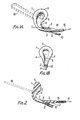
- the invention takes the form shown in Figure 1, and consists of two integrally connected limbs 1 and 2, the inner or upper limb 1 broadening out into a tongue or in elevation (see Figure IB) light bulb shaped plan, and the outer of lower limb 2 being narrower and not broadening out at its end.
- the limbs 1 and 2 together provide a generally U or V-shaped configuration, the inner face 3 of the lower limb of the U being generally flat or concave.
- the inner face 4 of the upper limb 1 affords a centrally disposed medially extending duct, channel, or groove 5 defined by the edges of the limb 1, which edges are slightly rounded at its far end 6.
- the edges 4 of the channel 5 may also be rounded along its length.
- the channel issues out of the end 6 of the limb 1 and extends around the base of the U some distance (e.g. about 20 to 30% e.g. 25% of the length) along the lower limb 2, where it terminates on the surface of the limb 2 in a rounded end 7.
- the channel 5 communicates with an internal duct 8, at or near its end 7, which duct extends more or less diagonally through the limb 2 to emerge through its outer face at 9, at or near the end of the limb 2. This angle enables the bladder to be emptied even when the woman is sitting down.
- the duct 8 is there connected to, or continues as a tube 10.
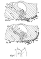
- the limb 1 of the device is inserted into the entrance of the vagina, and is positioned so as to be located in the vagina as shown in Figure 3A, with the limb 1 being placed against the anterior vaginal wall 11 the channel 5 being positioned so as to follow the course of the urethra 12. It is not essential for the limb 1 to extend as far into the vagina as shown in Figure 3A. It may be shorter, provided an adequate seal can be maintained between the vaginal wall 11 and the edges 4 of the channel 5.
- the lower limb 2 points forwardly and is positioned against the outer surface of the body, within the vulva 13.
- the urethral opening 14 is thus positioned within the channel 5. Any urine escaping from the urethral opening 14 will pass along the channel 5, through the duct 8 and pass into the tube 10 where it may be collected by any suitable means such as a receptacle attached to the patient's leg.
- the device is held in position by means of external tensioning means one form of which is a strap 15 which is attached to or is a continuation of the second limb 2 from its forward end 16.
- the strap 15 (which may be padded or sheathed for comfort) may conveniently be attached to a belt 17 as shown in Figure 4 and is maintained in tension by its own elasticity or that of the belt 17, or both.
- a plastics tube 16A which may extend (as shown in Figure 3B) from the end of limb 2 (to which, it may be connected) out beyond the vulva 13, e.g. as far as 16B (see Figure 3B). This prevents the tensioning means rubbing the user.
- the means 15 may only be elastic within such a tube and thereafter be connected to the belt by an inelastic connection.
- the belt may be elastic or inelastic. This tension causes the limb 1 to be pressed against the anterior vaginal wall 11.
- the necessary seal between the vaginal wall 11 and the edges 4 of the channel 5 may be enhanced by lining the edges 4 with any suitable material such as a soft pad, or a cohesive gum of suitable consistency may be used.
- suitable gums include a mixture of Karaya gum, glycerine and gelatine mixed to a putty-like consistency, or alternatively liquid poly- merssuch as a cellulose-polybutene combination may be used.
- Figure 3B shows a further modification in which a dorsal extension 1A of generally duck bill shape extends rearwardly from the top back face of the limb 1 towards or past the cervix, but stops short of the dorsal wall of the vagina and extends across this region of the vagina.
- a dorsal extension of this sort is also shown and described in Figure 20 (see reference 207). This extension helps maintain accurate lateral location of the device in use.
- the necessary support may be increased internally particularly against lateral movement.
- This may take the form of a generally rigid but resilient loop 18, which is attached to the back or outer face of the limb 1 as shown in Figures 1 and 3A by dashed lines.
- the belt and strap again hold the device in place and cause the limb 1 to be pressed against the anterior vaginal wall 11 in the position previously described.
- the loop 18 being pressed against the upper dorsal vaginal wall 19 behind the cervix 20 with the natural elasticity of the vaginal wall 19 helps to hold the device in place particularly against lateral movement.
- the device is shaped so as to be held in place between the anterior and dorsal vaginal walls, 11, 21 in the vaginal entrance as well as being held in place by the belt and strap.
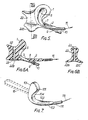
- the limbs I, 2 are generally as described above for the first embodiment, but the base of the U is extended to form a generally saddle-shaped protrusion 22, moulded to conform to the general shape of the lower dorsal vaginal wall 21 and provided on either side and its lower edge by outwardly and downwardly extending wings 22B and 22C which in use bear against the users external body surface outside the vagina.
- the device In use, the device is held in position by the combined pressure of the anterior wall 11 on the upper limb 1 and that of the dorsal wall 21 on the saddle-shaped protrusion 22 as well as the belt and strap.
- the protrusion 22 is provided with a generally vertically disposed duct 23 extending between its upper and lower surfaces, which duct serves to allow egress of natural vaginal fluids, and to permit easy removal of the device.
- the device may be made of any suitably flexible material such as rubber, or it may be made of a more rigid material such as polypropylene and provided with pads of compressible material for comfort, in the necessary regions.
- the structure should be sufficiently rigid to ensure secure location in the vagina and to enable the force exerted by the strap 15 to pull the limb 1 against the vaginal wall 11.
- the base of the U, between the limbs 1 and 2 may be made of a more flexible material to allow some hinging movement between the limbs, thus accommodating personal differences in vaginal shape.
- the loop. 18 is present the hinging embodiment can be used or the device can be made of more flexible material throughout.
- the use of a nonreactive material may be useful to patients with allergies to rubber or silicone products.
- This first version, the drainage version, of the invention deals with incontinence by collecting the urine.
- the second version, the restrictive version, of the invention mechanically causes retention of the urine.
- this restrictive version of the invention takes the form shown in Figure 7 and consists of two integrally connected limbs 101, 102.
- the limbs 101 and 102 together provide a generally U or V-shaped configuration, the inner face 103 of the lower limb 102 being generally flat or concave.
- the innerface 104 of the upper limb is generally flat or convex and terminates in an inwardly-facing protuberance 105, of which the edges are rounded as shown in Figure 7.
- the limb 101 of the device is inserted into the entrance to the vagina, and is positioned so as to be located in the vagina as shown in Figure 8 with the limb 101 being placed against the anterior vaginal wall 11, following the line of the urethra 12.
- the lower limb 102 points forwardly and is positioned against the outer surface of the body within the vulva 13.
- the device is held in position by means of tensioning means, one form of which is a strap 115 which is attached to or is a continuation of the lower limb 102 at its forward end 116.
- the strap 115 (which may be padded for comfort or sheathed as described above in connection with Figure 3B) may conveniently be attached to a belt 17 (as shown in Figure 4 above) and is maintained in tension by its own elasticity or that of the belt 17, or both.
- This tension causes the limb 101 to be pressed against the anterior vaginal wall 11 directly over the course of the urethra 12.
- the pressure of the limb 101, and particularly that due to the protuberance 105 causes the urethra 12 to collapse (as shown in Figure 8), so preventing urine flow.
- the necessary support may be increased internally particularly against lateral movement.
- This may take the form of a rigid loop 118 which is attached to the back or outer face of the limb 101 as shown in Figures 7 and 8 by dashed lines.
- the belt and strap again hold the device in place, the limb 101 being pressed against the anterior vaginal wall 11 in the position previously described.
- the loop 118 being pressed against the upper dorsal vaginal wall 19 behind the cervix 20 with the natural elasticity of the vaginal wall 19 helps hold the device in place particularly against lateral movement.
- the device is shaped so as to be held in place between the anterior and dorsal vaginal walls 11, 21, proximate the vaginal entrance as well as being held in place by the belt and strap.
- the limbs 101 and 102 are generally as described above for the first modification of the second embodiment but the base of the U or V is extended to form a generally saddle-shaped protrusion 122, moulded to conform with the general shape of the lower dorsal vaginal wall 21.
- the device is held in position by the combined pressure of the anterior wall 11 on the upper limb 1 and that of the dorsal wall 21 on the saddle-shaped protrusion 122 as well as the belt and strap.
- the protrusion 122 is provided with a generally vertically-disposed duct 123 extending between its upper and lower surfaces, which duct serves to allow egress of natural vaginal fluids and enables the device to be removed easily, and if desired wings 122B and C (not shown) as described above for Figure 5.
- the limb 101 it is not essential for the limb 101 to extend as far into the vagina as shown in Figure 8. It may be shorter, provided that it extends far enough above the urethral opening 14 to allow the occlusion of the urethra 12 without significant leakage.
- the protuberance 105 at the end of the limb 101 is likewise not essential to the invention; the pressure of the limb 101 alone on the urethra 12 can be sufficient to cause it to collapse but the protuberance aids certainty of operation.
- the device may be made of any suitably flexible material such as rubber, or it may be made of a more rigid material such as polypropylene, and provided with pads of compressible material, for comfort, in the necessary regions.
- the structure should be sufficiently rigid to ensure secure location in the vagina, and to enable the force exerted by the strap 15 to pull the limb 101 and the protuberance 105 against the interior vaginal wall 11 sufficiently hard to occlude the urethra 12, If the device is made of a generally rigid material the base of the U, between the limbs 101 and 102, may be made of a more flexible material to allow some hinging movement between the limbs, thus accommodating personal differences in vaginal shape. When the loop 118 is present the hinging embodiment may be used or the device may be made of a more flexible material throughout.
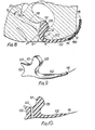
- the device in this third modification of the second embodiment is a polypropylene moulding about 3 mms thick.
- the device before insertion has a shepherd-crook longitudinal cross section having a long straight portion 52 corresponding to the limb 102 having a connecting link 66 at its free end and broadening into a paddle shaped end 75 at the end where it curves round to form a broadened plate 51 of egg saped plan view corresponding to the limb 1 in the first embodiment.
- This plate 51 is curved inwardly in cross-section towards the portion 52 so as to afford a protuberance 55 effective to apply pressure to the urethra and thus occlude it in use.
- the straight portion 76 of the limb 52 is preferably sheathed in soft polymer or rubber 77 so as to prevent discomfort or excoriation of the mucous membrane at the lower end and may be made sufficiently flexible to conform in use to the user's body as shown in Figure 14.
- the edges 74 of the plate 51 are carefully moulded to rounded shapes with the same aim in mind, and in addition the soft sheathing may extend to cover the plate 51 as is also shown at 78 in Figure 14.
- FIG. 15 and 16 has an inner or upper limb 151 and an outer or lower limb 152 from the end of which extends tensioning means(indicated diagrammatically at 15) as in the other embodiments.
- the upper end of the inner limb 152 is oval in cross section ( Figure 16) the rigid back face 155 carrying a compressible cushion 157, e.g. having a foam or fluid filled interior 156 and an impervious covering 158.
- This cushion is of such compressibility as under the pressure of the tensioning means 15 exerted via the back face 155 to occlude the urethra and prevent urine flow but also to be capable of being further compressed when muscular pressure is exerted on the bladder to force urine down the urethra and past this cushion 157.
- the arrangement in Figures 17 and 18 has the cushion 157 replaced by a fluid filled bag, e.g. an airbag 160, again mounted on the front side of the rigid back 155 and connected via a tube 161 with a small hand operable pump 162 which in use is located outside the body.
- a fluid filled bag e.g. an airbag 160
- the pump can be used to inflate the airbag, e.g. to the position shown in dotted lines in Figure 18 to shut off urine flow.
- the pump 162 is also provided with a release valve 163 is that the airbag can be easily deflated to permit discharge of urine.
- duct means will be provided to allow discharge of urine.
- a duct may merely be an opening through the device, e.g. the limb 151 or may be a duct such as shown in the arrangement of Figures 1 to 6.
- FIGS. 19 and 20 show the third embodiment of the invention, the stress incontinence version.
- the inner limb 201 is generally of spoon shape whilst the outer limb 202 is narrower.
- the tensioning means extend away from the end of the limb 202 as in the other embodiments and as illustrated diagrammatically at 15.
- a slot-like duct 205 extends around the bend which joins the limbs 201 and 202 enabling urineto be discharged from the urethral opening 14 without the device needing to be removed from the vagina.
- the top edge 206 of the inner limb 201 holds the users urethra in or near the normal position and reduces or alleviates stress incontinence.
- the arrangement in Figure 20 has a further feature in the dorsal extension 207 which is akin to the extension IA shown in Figure 3B and is of similar duck-bill shape and extent (extending to near the cervix but stopping short thereof and extending across the vagina) and function (helping to maintain lateral location).
Landscapes
- Health & Medical Sciences (AREA)
- Urology & Nephrology (AREA)
- Public Health (AREA)
- Life Sciences & Earth Sciences (AREA)
- Veterinary Medicine (AREA)
- Engineering & Computer Science (AREA)
- Biomedical Technology (AREA)
- Heart & Thoracic Surgery (AREA)
- Vascular Medicine (AREA)
- General Health & Medical Sciences (AREA)
- Animal Behavior & Ethology (AREA)
- Oral & Maxillofacial Surgery (AREA)
- Cardiology (AREA)
- Transplantation (AREA)
- Epidemiology (AREA)
- Nursing (AREA)
- Orthopedic Medicine & Surgery (AREA)
- Orthopedics, Nursing, And Contraception (AREA)
Claims (12)
Priority Applications (1)
| Application Number | Priority Date | Filing Date | Title |
|---|---|---|---|
| AT84903646T ATE36644T1 (de) | 1983-09-27 | 1984-09-27 | Inkontinenzgeraet fuer weibliche personen. |
Applications Claiming Priority (6)
| Application Number | Priority Date | Filing Date | Title |
|---|---|---|---|
| GB08325847A GB2147809A (en) | 1983-09-27 | 1983-09-27 | Urethral occlusion device |
| GB8325848 | 1983-09-27 | ||
| GB08325848A GB2148715B (en) | 1983-09-27 | 1983-09-27 | Urine drainage device |
| GB8325847 | 1983-09-27 | ||
| GB08423591A GB2146901B (en) | 1983-09-27 | 1984-09-18 | Incontinence devices for women |
| GB8423591 | 1984-09-18 |
Publications (2)
| Publication Number | Publication Date |
|---|---|
| EP0157844A1 EP0157844A1 (de) | 1985-10-16 |
| EP0157844B1 true EP0157844B1 (de) | 1988-08-24 |
Family
ID=27262200
Family Applications (1)
| Application Number | Title | Priority Date | Filing Date |
|---|---|---|---|
| EP84903646A Expired EP0157844B1 (de) | 1983-09-27 | 1984-09-27 | Inkontinenzgerät für weibliche personen |
Country Status (6)
| Country | Link |
|---|---|
| US (1) | US4875898A (de) |
| EP (1) | EP0157844B1 (de) |
| AU (1) | AU3438384A (de) |
| CA (1) | CA1242124A (de) |
| DE (1) | DE3473562D1 (de) |
| WO (1) | WO1985001438A1 (de) |
Families Citing this family (32)
| Publication number | Priority date | Publication date | Assignee | Title |
|---|---|---|---|---|
| US5176664A (en) * | 1990-10-09 | 1993-01-05 | Kenneth Weisman | Female voiding assist device and method |
| US5520606A (en) * | 1990-10-18 | 1996-05-28 | Schoolman; Arnold | Mechanical urinary sphincter device |
| US5224494A (en) * | 1992-03-19 | 1993-07-06 | Enhorning Goran E | Vaginal pessary |
| US6048306A (en) * | 1998-08-14 | 2000-04-11 | Theodore E. Spielberg | Non-invasive dual acting urological press for the prevention of female incontinence |
| US6699174B1 (en) | 2001-01-18 | 2004-03-02 | Patricia A. Bennett | Female urinary incontinence device |
| US6458072B1 (en) | 2001-04-19 | 2002-10-01 | Kimberly-Clark Worldwide, Inc. | Urinary incontinence device |
| US6478726B1 (en) | 2001-04-19 | 2002-11-12 | Kimberly-Clark Worldwide, Inc. | Method for alleviating female urinary incontinence |
| US6558370B2 (en) | 2001-06-05 | 2003-05-06 | Kimberly-Clark Worldwide, Inc. | Urinary incontinence device |
| US6770025B2 (en) | 2002-09-18 | 2004-08-03 | Kimberly-Clark Worldwide, Inc. | Molar shaped vaginal incontinence insert |
| US6676594B1 (en) | 2002-09-18 | 2004-01-13 | Kimberly-Clark Worldwide, Inc. | C-shaped vaginal incontinence insert |
| US6808485B2 (en) | 2002-12-23 | 2004-10-26 | Kimberly-Clark Worldwide, Inc. | Compressible resilient incontinence insert |
| GB2435215B (en) * | 2006-02-17 | 2011-08-03 | Gaynor Morgan | Vaginal device |
| FR2900817B1 (fr) | 2006-05-12 | 2008-12-19 | Gambro Lundia Ab | Bandage a usage medical pour un tube implante dans un patient, ainsi que le procede d'application de ce bandage sur la peau d'un patient |
| US10004584B2 (en) | 2006-07-10 | 2018-06-26 | First Quality Hygienic, Inc. | Resilient intravaginal device |
| US8177706B2 (en) | 2006-07-10 | 2012-05-15 | Mcneil-Ppc, Inc. | Method of treating urinary incontinence |
| US8613698B2 (en) | 2006-07-10 | 2013-12-24 | Mcneil-Ppc, Inc. | Resilient device |
| CN104257450B (zh) | 2006-07-10 | 2017-05-10 | 第一次质量卫生公司 | 弹性装置 |
| US10219884B2 (en) | 2006-07-10 | 2019-03-05 | First Quality Hygienic, Inc. | Resilient device |
| US20090095304A1 (en) * | 2007-10-15 | 2009-04-16 | Sharon Ann Richardson | Vaginal pessary for the management of stress incontinence |
| US8202263B2 (en) * | 2009-02-11 | 2012-06-19 | Michael Feloney | Vaginal barrier and female urethral catheterization assisting device |
| US9408683B2 (en) | 2009-05-27 | 2016-08-09 | Parapatch, Inc. | Method and device for treating female pelvic nerve dysfunction |
| US8684008B2 (en) * | 2009-05-27 | 2014-04-01 | Cora St. Anne | Method and device for female urinary incontinence |
| CA2763361C (en) | 2009-05-28 | 2018-05-01 | Contine Corporation | Correction of stress urinary incontinence |
| US9072582B2 (en) | 2013-03-14 | 2015-07-07 | Ryan Maaskamp | Rectocele device |
| US9216105B2 (en) | 2013-03-14 | 2015-12-22 | Medicele, Llc. | Rectocele and cystocele device |
| US9186234B2 (en) | 2013-04-23 | 2015-11-17 | Terell Reglin | Apparatus for promoting urorectal organ emptying and related method |
| US20160331407A1 (en) * | 2015-05-14 | 2016-11-17 | LGO Medical, LLC | Evacuation Assist Device and Methods |
| USD798462S1 (en) | 2016-04-01 | 2017-09-26 | Parapatch, Inc. | Clitoral adhesive device |
| AU2017395751B2 (en) | 2017-01-24 | 2023-11-02 | Liv Labs Inc. | Stress urinary incontinence (SUI) device |
| US11259957B2 (en) | 2019-09-25 | 2022-03-01 | Ryan Maaskamp | Rectocele guide |
| WO2023049175A1 (en) * | 2021-09-23 | 2023-03-30 | Purewick Corporation | Fluid collection assemblies including one or more leak prevention features |
| USD1071181S1 (en) | 2022-04-20 | 2025-04-15 | Liv Labs Inc. | Urinary incontinence device |
Family Cites Families (18)
| Publication number | Priority date | Publication date | Assignee | Title |
|---|---|---|---|---|
| US2638093A (en) * | 1949-12-20 | 1953-05-12 | Kulick George | Vaginal insert |
| GB867348A (en) * | 1958-09-25 | 1961-05-03 | Louis A Terman | Personal sanitary convenience |
| US3116734A (en) | 1961-06-07 | 1964-01-07 | Louis A Terman | Intravaginal urinal |
| GB1115727A (en) * | 1965-11-15 | 1968-05-29 | Harry Hall Tomkin | Apparatus controlling incontinence in the female |
| GB1193261A (en) * | 1966-02-28 | 1970-05-28 | Philip Dent | Improvements in and relating to Sanitary Appliances for Personal Use |
| GB1216662A (en) * | 1967-03-09 | 1970-12-23 | Harry Ratcliffe | A personal urine collecting device |
| US3528423A (en) * | 1967-06-20 | 1970-09-15 | John W Lee | Female incontinence device |
| GB1289107A (de) * | 1968-12-10 | 1972-09-13 | ||
| GB1315964A (en) * | 1969-09-26 | 1973-05-09 | Edwards Le | Incontinence device for female use |
| US3705575A (en) * | 1969-09-26 | 1972-12-12 | Lynn Euryl Edwards | Incontinence device for female use |
| GB1253497A (en) * | 1970-02-20 | 1971-11-17 | Jacob Paul Ellis | Urinary collection device |
| US3661155A (en) * | 1970-02-24 | 1972-05-09 | Rosemary Lindan | Female urinary incontinence device |
| GB1359343A (en) * | 1972-11-07 | 1974-07-10 | Levy N | Pneumatic inhibitor for female incontinence |
| US4194508A (en) * | 1978-03-28 | 1980-03-25 | Anderson Kenneth E | External female urinary drainage device |
| US4246901A (en) * | 1978-05-30 | 1981-01-27 | Nasa | Urine collection device |
| US4270539A (en) * | 1979-04-27 | 1981-06-02 | Nasa | Urine collection apparatus |
| GB2090144A (en) * | 1980-12-31 | 1982-07-07 | Thames Valley Medical Ltd | Female incontinence device |
| US4496355A (en) * | 1982-11-16 | 1985-01-29 | Illinois Tool Works Inc. | External female urinary appliance |
-
1984
- 1984-09-26 CA CA000464018A patent/CA1242124A/en not_active Expired
- 1984-09-27 WO PCT/GB1984/000331 patent/WO1985001438A1/en not_active Ceased
- 1984-09-27 DE DE8484903646T patent/DE3473562D1/de not_active Expired
- 1984-09-27 EP EP84903646A patent/EP0157844B1/de not_active Expired
- 1984-09-27 AU AU34383/84A patent/AU3438384A/en not_active Abandoned
-
1989
- 1989-02-06 US US07/307,235 patent/US4875898A/en not_active Expired - Lifetime
Also Published As
| Publication number | Publication date |
|---|---|
| US4875898A (en) | 1989-10-24 |
| CA1242124A (en) | 1988-09-20 |
| DE3473562D1 (en) | 1988-09-29 |
| AU3438384A (en) | 1985-04-23 |
| EP0157844A1 (de) | 1985-10-16 |
| WO1985001438A1 (en) | 1985-04-11 |
Similar Documents
| Publication | Publication Date | Title |
|---|---|---|
| CA1242124A (en) | Incontienence devices for women | |
| US4889533A (en) | Female urinary collection devices having hollow-walled filled urine receptacles | |
| US6428521B1 (en) | Female external catheter device | |
| US6131575A (en) | Urinary incontinence device | |
| US6592560B2 (en) | Urine retention and collection devices for incontinent women | |
| US4681572A (en) | Female urinary incontinence device | |
| US4904248A (en) | Female incontinent urine collection device | |
| US4568339A (en) | Female incontinence device | |
| US5036867A (en) | Urinary incontinence device | |
| US4986823A (en) | Urinary aid for human females | |
| US20110028922A1 (en) | Female External Incontinence Device | |
| US3116734A (en) | Intravaginal urinal | |
| AU3791399A (en) | Externally supported female urinary collector | |
| CA1214086A (en) | Female urinary incontinence device | |
| US7476219B2 (en) | Urinary incontinence device | |
| GB2146901A (en) | Incontinence devices for women | |
| JPS5997661A (ja) | 女性失調症用装置 | |
| AU728736B2 (en) | Urinary incontinence device | |
| JPH04500471A (ja) | 尿排泄装置 | |
| CN215875095U (zh) | 一种治疗尿失禁的男性吊带 | |
| GB2147809A (en) | Urethral occlusion device | |
| GB2148715A (en) | Urine drainage device | |
| CN222426444U (zh) | 一种男性留置导尿管防溢卫生棉 | |
| MXPA99005457A (es) | Dispositivo de incontinencia urinaria |
Legal Events
| Date | Code | Title | Description |
|---|---|---|---|
| PUAI | Public reference made under article 153(3) epc to a published international application that has entered the european phase |
Free format text: ORIGINAL CODE: 0009012 |
|
| AK | Designated contracting states |
Designated state(s): AT BE CH DE FR GB LI LU NL SE |
|
| 17P | Request for examination filed |
Effective date: 19851004 |
|
| 17Q | First examination report despatched |
Effective date: 19861217 |
|
| GRAA | (expected) grant |
Free format text: ORIGINAL CODE: 0009210 |
|
| AK | Designated contracting states |
Kind code of ref document: B1 Designated state(s): AT BE CH DE FR LI LU NL SE |
|
| REF | Corresponds to: |
Ref document number: 36644 Country of ref document: AT Date of ref document: 19880915 Kind code of ref document: T |
|
| REF | Corresponds to: |
Ref document number: 3473562 Country of ref document: DE Date of ref document: 19880929 |
|
| ET | Fr: translation filed | ||
| PLBE | No opposition filed within time limit |
Free format text: ORIGINAL CODE: 0009261 |
|
| STAA | Information on the status of an ep patent application or granted ep patent |
Free format text: STATUS: NO OPPOSITION FILED WITHIN TIME LIMIT |
|
| 26N | No opposition filed | ||
| EPTA | Lu: last paid annual fee | ||
| EAL | Se: european patent in force in sweden |
Ref document number: 84903646.2 |
|
| PGFP | Annual fee paid to national office [announced via postgrant information from national office to epo] |
Ref country code: SE Payment date: 20020904 Year of fee payment: 19 |
|
| PGFP | Annual fee paid to national office [announced via postgrant information from national office to epo] |
Ref country code: FR Payment date: 20020910 Year of fee payment: 19 |
|
| PGFP | Annual fee paid to national office [announced via postgrant information from national office to epo] |
Ref country code: AT Payment date: 20020911 Year of fee payment: 19 |
|
| PGFP | Annual fee paid to national office [announced via postgrant information from national office to epo] |
Ref country code: LU Payment date: 20020927 Year of fee payment: 19 |
|
| PGFP | Annual fee paid to national office [announced via postgrant information from national office to epo] |
Ref country code: NL Payment date: 20020930 Year of fee payment: 19 |
|
| PGFP | Annual fee paid to national office [announced via postgrant information from national office to epo] |
Ref country code: CH Payment date: 20021001 Year of fee payment: 19 |
|
| PGFP | Annual fee paid to national office [announced via postgrant information from national office to epo] |
Ref country code: DE Payment date: 20021002 Year of fee payment: 19 |
|
| PGFP | Annual fee paid to national office [announced via postgrant information from national office to epo] |
Ref country code: BE Payment date: 20021129 Year of fee payment: 19 |
|
| PG25 | Lapsed in a contracting state [announced via postgrant information from national office to epo] |
Ref country code: LU Free format text: LAPSE BECAUSE OF NON-PAYMENT OF DUE FEES Effective date: 20030927 Ref country code: AT Free format text: LAPSE BECAUSE OF NON-PAYMENT OF DUE FEES Effective date: 20030927 |
|
| PG25 | Lapsed in a contracting state [announced via postgrant information from national office to epo] |
Ref country code: SE Free format text: LAPSE BECAUSE OF NON-PAYMENT OF DUE FEES Effective date: 20030928 |
|
| PG25 | Lapsed in a contracting state [announced via postgrant information from national office to epo] |
Ref country code: LI Free format text: LAPSE BECAUSE OF NON-PAYMENT OF DUE FEES Effective date: 20030930 Ref country code: CH Free format text: LAPSE BECAUSE OF NON-PAYMENT OF DUE FEES Effective date: 20030930 Ref country code: BE Free format text: LAPSE BECAUSE OF NON-PAYMENT OF DUE FEES Effective date: 20030930 |
|
| BERE | Be: lapsed |
Owner name: *EAKIN THOMAS GEORGE Effective date: 20030930 |
|
| PG25 | Lapsed in a contracting state [announced via postgrant information from national office to epo] |
Ref country code: NL Free format text: LAPSE BECAUSE OF NON-PAYMENT OF DUE FEES Effective date: 20040401 Ref country code: DE Free format text: LAPSE BECAUSE OF NON-PAYMENT OF DUE FEES Effective date: 20040401 |
|
| EUG | Se: european patent has lapsed | ||
| REG | Reference to a national code |
Ref country code: CH Ref legal event code: PL |
|
| PG25 | Lapsed in a contracting state [announced via postgrant information from national office to epo] |
Ref country code: FR Free format text: LAPSE BECAUSE OF NON-PAYMENT OF DUE FEES Effective date: 20040528 |
|
| NLV4 | Nl: lapsed or anulled due to non-payment of the annual fee |
Effective date: 20040401 |
|
| REG | Reference to a national code |
Ref country code: FR Ref legal event code: ST |