EP0157977A2 - Appareil pour l'évaluation de matériel en particules - Google Patents
Appareil pour l'évaluation de matériel en particules Download PDFInfo
- Publication number
- EP0157977A2 EP0157977A2 EP84305773A EP84305773A EP0157977A2 EP 0157977 A2 EP0157977 A2 EP 0157977A2 EP 84305773 A EP84305773 A EP 84305773A EP 84305773 A EP84305773 A EP 84305773A EP 0157977 A2 EP0157977 A2 EP 0157977A2
- Authority
- EP
- European Patent Office
- Prior art keywords
- fraction
- sample
- frame
- carriage
- receptacle
- Prior art date
- Legal status (The legal status is an assumption and is not a legal conclusion. Google has not performed a legal analysis and makes no representation as to the accuracy of the status listed.)
- Withdrawn
Links
- 239000011236 particulate material Substances 0.000 title claims abstract description 7
- 238000011156 evaluation Methods 0.000 title claims description 4
- 230000003287 optical effect Effects 0.000 claims abstract description 22
- 238000005070 sampling Methods 0.000 claims abstract description 16
- 239000002245 particle Substances 0.000 claims abstract description 15
- 239000000463 material Substances 0.000 claims abstract description 11
- 238000000034 method Methods 0.000 claims abstract description 9
- 230000008569 process Effects 0.000 claims abstract description 9
- 238000000926 separation method Methods 0.000 claims abstract description 6
- 241000208125 Nicotiana Species 0.000 claims description 49
- 235000002637 Nicotiana tabacum Nutrition 0.000 claims description 49
- 238000007689 inspection Methods 0.000 claims description 8
- 230000000694 effects Effects 0.000 claims description 3
- 230000005484 gravity Effects 0.000 claims description 2
- 239000000725 suspension Substances 0.000 claims description 2
- 239000000126 substance Substances 0.000 claims 1
- 238000007873 sieving Methods 0.000 description 9
- 238000005259 measurement Methods 0.000 description 7
- 238000004458 analytical method Methods 0.000 description 6
- 235000019504 cigarettes Nutrition 0.000 description 3
- 230000005355 Hall effect Effects 0.000 description 2
- 230000009471 action Effects 0.000 description 2
- 230000008859 change Effects 0.000 description 2
- 239000000428 dust Substances 0.000 description 2
- 238000010191 image analysis Methods 0.000 description 2
- 238000005303 weighing Methods 0.000 description 2
- 238000004364 calculation method Methods 0.000 description 1
- 230000003247 decreasing effect Effects 0.000 description 1
- 238000010586 diagram Methods 0.000 description 1
- 238000006073 displacement reaction Methods 0.000 description 1
- 238000010894 electron beam technology Methods 0.000 description 1
- 238000005516 engineering process Methods 0.000 description 1
- 239000010419 fine particle Substances 0.000 description 1
- 239000012530 fluid Substances 0.000 description 1
- 230000006870 function Effects 0.000 description 1
- 210000003128 head Anatomy 0.000 description 1
- 238000003384 imaging method Methods 0.000 description 1
- 230000001939 inductive effect Effects 0.000 description 1
- 230000000750 progressive effect Effects 0.000 description 1
- 210000001525 retina Anatomy 0.000 description 1
- 238000004088 simulation Methods 0.000 description 1
- 238000002834 transmittance Methods 0.000 description 1
Images




Classifications
-
- G—PHYSICS
- G01—MEASURING; TESTING
- G01N—INVESTIGATING OR ANALYSING MATERIALS BY DETERMINING THEIR CHEMICAL OR PHYSICAL PROPERTIES
- G01N15/00—Investigating characteristics of particles; Investigating permeability, pore-volume or surface-area of porous materials
- G01N15/02—Investigating particle size or size distribution
- G01N15/0272—Investigating particle size or size distribution with screening; with classification by filtering
-
- A—HUMAN NECESSITIES
- A24—TOBACCO; CIGARS; CIGARETTES; SIMULATED SMOKING DEVICES; SMOKERS' REQUISITES
- A24B—MANUFACTURE OR PREPARATION OF TOBACCO FOR SMOKING OR CHEWING; TOBACCO; SNUFF
- A24B3/00—Preparing tobacco in the factory
- A24B3/18—Other treatment of leaves, e.g. puffing, crimpling, cleaning
-
- A—HUMAN NECESSITIES
- A24—TOBACCO; CIGARS; CIGARETTES; SIMULATED SMOKING DEVICES; SMOKERS' REQUISITES
- A24B—MANUFACTURE OR PREPARATION OF TOBACCO FOR SMOKING OR CHEWING; TOBACCO; SNUFF
- A24B5/00—Stripping tobacco; Treatment of stems or ribs
-
- A—HUMAN NECESSITIES
- A24—TOBACCO; CIGARS; CIGARETTES; SIMULATED SMOKING DEVICES; SMOKERS' REQUISITES
- A24B—MANUFACTURE OR PREPARATION OF TOBACCO FOR SMOKING OR CHEWING; TOBACCO; SNUFF
- A24B7/00—Cutting tobacco
-
- G—PHYSICS
- G01—MEASURING; TESTING
- G01N—INVESTIGATING OR ANALYSING MATERIALS BY DETERMINING THEIR CHEMICAL OR PHYSICAL PROPERTIES
- G01N15/00—Investigating characteristics of particles; Investigating permeability, pore-volume or surface-area of porous materials
- G01N15/10—Investigating individual particles
- G01N15/14—Optical investigation techniques, e.g. flow cytometry
- G01N15/1468—Optical investigation techniques, e.g. flow cytometry with spatial resolution of the texture or inner structure of the particle
Definitions
- This invention relates to apparatus for the evaluation of particulate material e.g., cut tobacco, in relation to its particle geometry.
- the particle geometry of cut tobacco is related to the filling and capacity and firmness of cut tobacco and accordingly it is customary to assess the geometry and to adjust the associated tobacco machinery accordingly.
- assessment by optical measurement as at present carried out takes days to obtain results.
- filling capacity we mean specific volume in cc/gm and firmness is the pressure per volumetric strain.
- An object of the present invention is to provide apparatus for image analysis whereby rapid determination of particle geometry and especially for use with cut tobacco although applicable to other particulate material.
- the length of the strands in the second fraction is matched to the limit of fluidity.
- the inventor has observed that separation of the strands is possible if the optimum value of strand length can be obtained at which the tobacco becomes fluid in the same way as the tobacco becomes fluidic at the zone in the cigarette maker when the'tobacco is poured in a continuous stream into a channel prior to being wrapped in paper to form a continuous rod.
- the first fraction comprises very long tangled strands which will not pass the top sieve. They are longer than 5 mm and up to 20 mm and thus longer than needed for cigarette making. They are not analysed because they will be broken into smaller particles prior to cigarette making and so are only weighed as a fraction.
- the second fraction is the medium and short strands, which pass the first sieve having preferably 5 mm diameter holes and are easily separable. They are generally from 1 to 5 mm long, although some slightly longer strands can find their way through the holes, and comprise the fraction which one is concerned to improve in length by process improvements in order to enhance filling power. This second fraction which is the most fluidic is weighed and optically analysed.
- the third fraction is the fines or dust, below 1 mm in length, which decrease filfing power and only needs to be weighed.
- a quantity of cut tobacco is first entered into a vibratory tobacco feeder 1, driven by stepping motors 2, which feeder automatically meters the tobacco in a controlled manner into a sieving section 3. It is necessary to control the tobacco feed rate or the amount of tobacco into the sieving section so as to give efficient sieving and to avoid choking the sieving section 3.
- the sieving section 3 consists of two sieve layers depending on the degree of size classification required.
- the upper sieve separates long strands of tobacco, and the lower sieve separates intermediate size strands. Fine particles of tobacco fall onto a tray 4.
- the sieves vibrate for a length of time to allow the tobacco to be efficiently classified.
- the sieving section will be further described in relation to Figure 2.
- the classified tobacco fractions lying on the sieve are transferred to the bins of weighers 6a,6b and 6c in the weighing area 6.
- the mass of tobacco in each fraction is computed by subtraction as each bin is emptied.
- a representative sample of tobacco is now taken from the intermediate size fraction following the weigher 6b by means of a sampling device 7 to be described later, and deposited on an optical inspection surface 8. The remaining tobacco is transferred out of the machine by a conveyor system 9.
- the sample of tobacco is now spread on the table 8 by vibrating the table.
- the table 8 provides an optical surface on which optical inspection can be carried out.
- An optical scanning head 10 located on a support 11 over the surface 8 measures light reflectance from, or light transmittance through the tobacco strands and provides optical data to an electronic vision system 13 e.g., Intel Corporation California, USA, model 8086 interfaced with a frame freeze facility 14 e.g., from Imaging Technology Inc. California, USA.
- the optical scanning head 10 may be a line scan or array camera, e.g., a charge coupled device (CCD) line scan or image array.
- CCD charge coupled device
- the head could instead be a raster scan ' electron beam grey scale or colour camera which need not necessarily sense wavelengths of light that are sensed by the human retina.
- the vision system 13 analyses the geometry (i.e.., length, width, curvature) and/or the colour of the tobacco strands and presents the conclusions on a display 14.
- the geometry and/or colour is analysed by sampling the intensity and wavelength of light at predetermined pixel areas or points. These data are provided by the optical scanner and stored in corresponding electronic memory locations and subsequently processed using electronic logic.
- Electronic logic is defined as software, digital logic and.analogue electronics.
- the vision system may be calibrated by either measuring the size of a predetermined reference image in the field of view or by adjusting the image magnification such as to allow the predetermined image to encompass certain number of pixels.
- the conclusions are also used to control the behaviour of associated tobacco machinery, so as to achieve predetermined objectives such as strand cut width.
- the tobacco cutter would produce the set point cut width using the vision system-as a measurement device.
- the sample is now removed from the optical surface to allow the analysis of a fresh sample.
- a microcomputer 18 controls the actions of all the components including the stepping motors, electromagnetic vibrators, load cell, amplitude sensor and position switches in the apparatus by way of a digital input/output card 16, a power drive rack 19 and wiring loom 20 and also analyses the weight measurements of the classified tobacco.
- the conclusions drawn from the weight and geometry measurements are presented on the t.v. monitor 14 and may also be used to control the behaviour of associated tobacco machinery.
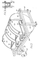
- the sieving section 3 is shown in Figure 2 and comprises an entry opening 22a leading to three stacked trays 21, 22, 23 of which the top and middle trays are sieves. Sieve layers are shown at 24.
- a transparent top 15 reduces tobacco and moisture loss.
- the bottom tray 23 is supported on a carriage 23a suspended adjacent to its opposite ends on transverse rods 25, 26 that are mounted on the lower ends of four upright suspension bars 28.
- the upper ends of these bars are connected to variable radius bearings 29 carried by transverse spindles 30 driven by stepping motors 31, 32 through flexible couplers 33.
- the spindles 30 are mounted in blocks 35 on a frame 36 which is supported by suitable supports (not shown).
- Each of the spindles also carries two variable radius counter masses 37.
- Two levers 40, 41 are pivoted to the frame 36 at 39 and are connected by connecting rods 42 to pivots 43 which are mounted on the tray at the centre of gra vity of the tray and bin.
- the levers 40 are connected together by a bridge 45 which is vertically adjustable by screw 46 operated by a stepping motor 47.
- Each spindle 30 has a Hall effect switch 48 associated with it to give a reference point for the step motor 31, 32.
- a light sensor 50 serves to give a constant tobacco carpet height on to the top sieve layer.
- the angle between the levers and the connecting rods 42 can be adjusted so that the pivotal connection 44 can be above or below the line between 43 and 39 and according to this adjustment the tray will be given a jerking motion to throw the tobacco forwards or backwards at controllable speed.
- An optical switch 54, windows 55, and reflector 56 serve to indicate when the bins are full.
- the bins are pivotally mounted on an inner frame 58 which is pivoted at 59 to in outer frame 60.
- the frame 60 ids pivotally mounted at the upper ends of columns 61 and is connected by links 62, 63 to pivots at the lower ends of the columns.
- the bins are drivable independantly about their pivots by stepping motors 64 through a toothed belt on drive 65.
- the frame 60 has a projecting arm 65 which carries a load cell 66 which measures the weight of tobacco in the bins and an adjustable spring 67 to offset the weight of the bins and links.
- wiper blades 70 driven by a step motor 71.
- a sampling cup 75 ( Figure 4) can be reciprocated horizontally below the outlet of the central bin 52 so as to collect a tobacco sample as the bin is rotated to tip out a stream of tobacco.
- a representative sample is obtained.
- the entire contents are tipped out and the reciprocation matched to the flow so that the cup fills just as the bin empties. In this way the sample is representative of the entire contents of the bin.
- a series of samples may be taken on progressive tipping of the bin and successively analysed.
- the software controlling the sampling and tipping may be written in such a manner that after analysis of say a succession of two or three samples being found to fall within set parameters no further sampling of the batch within the bin takes place, the bin simply emptying the conveyor 9.
- the cup is mounted on one end of a rod 77 which can be rotated about its axis so as to present the cup 75 in an upright tobacco receiving position and can be rotated to invert the cup in order to empty the tobacco from it.
- the rod is mounted in a carriage 78 which is slidably mounted by wheels 79 on guideways 80. The rotary movements of the rod are limited by stops 81.
- the rod carries a pinion 83 in gear with a rack 84 slidably mounted in the carriage 78, and attached to a spindle 85 which is urged by a spring 82 on the direction which keeps the cup 75 upright.
- the carriage is mounted on a toothed belt 86 which is engaged by pinions 87, 88 the latter being drivable by a stepping motor 90. Projecting between the runs of the belt from the guideways is a stop pin 91. When the carriage is driven towards the left ( Figure 4) the carriage comes into engagement with the stop pin 91 and further movement causes the rack 84 to slide against the action of the spring 82 thereby rotating the pinion 83 and rod 77 to invert the cup 75.
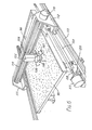
- the cup 75 empties the tobacco on to a vibrating table 95, Figures 5 and 6 (shown at 6 in Figure 1) at a position indicated at 96 ( Figure 6).
- the table is attached to a cruciform frame 97 at four positions 98 and the arms of the frame ard seated on four vibration mounting springs 100 respectively.
- These springs are fixed to a sub-frame 101 which is fixed to a suitable foundation by brackets 102.
- the centre of the frame 97 is mounted on an electromagnetic vibrator 102 which provides a vertical force moving function.
- An inductive linear displacement sensor 103 detects the amplitude of vibration.
- the table is horizontal and vibration causes the tobacco to spread out over the table. On completion of the optical inspection the table is cleared of tobacco by a wiper blade attached to the camera x-y carriage.
- the camera 105 for the inspection of the tobacco is provided with focus and servo-zoom device. Associated with the camera are a red filter 106, a green filter 107, and a transparent plate 108 which can be moved vertically and serves to flatten a small area of tobacco on to the table while it is under observation which permits good focus and forces the tobacco into a plane for accurate strand measurement.
- the camera is mounted on a gantry 104 supporting a carriage 109 that is slidable on guideways 110 transversely of the table.
- the guideways 110 are mounted on plates 111, 112 slidable on rails 113.
- the carriage 109 is movable transversely by a stepping motor 115 and screw 116 and the gantry is movable longitudinally by a stepping motor 117 and screw 118.
- the motors 115, 117 the camera can be caused to scan over a required area of the table.
Landscapes
- Chemical & Material Sciences (AREA)
- Dispersion Chemistry (AREA)
- Physics & Mathematics (AREA)
- Health & Medical Sciences (AREA)
- Life Sciences & Earth Sciences (AREA)
- Analytical Chemistry (AREA)
- Biochemistry (AREA)
- General Health & Medical Sciences (AREA)
- General Physics & Mathematics (AREA)
- Immunology (AREA)
- Pathology (AREA)
- Manufacturing Of Cigar And Cigarette Tobacco (AREA)
- Jigging Conveyors (AREA)
Applications Claiming Priority (6)
| Application Number | Priority Date | Filing Date | Title |
|---|---|---|---|
| GB8323206 | 1983-08-30 | ||
| GB838323207A GB8323207D0 (en) | 1983-08-30 | 1983-08-30 | Feeding of particulate material |
| GB838323208A GB8323208D0 (en) | 1983-08-30 | 1983-08-30 | Sampling of particulate material |
| GB8323208 | 1983-08-30 | ||
| GB838323206A GB8323206D0 (en) | 1983-08-30 | 1983-08-30 | Evaluation of particulate material |
| GB8323207 | 1983-08-30 |
Publications (2)
| Publication Number | Publication Date |
|---|---|
| EP0157977A2 true EP0157977A2 (fr) | 1985-10-16 |
| EP0157977A3 EP0157977A3 (fr) | 1986-02-05 |
Family
ID=27262192
Family Applications (1)
| Application Number | Title | Priority Date | Filing Date |
|---|---|---|---|
| EP84305773A Withdrawn EP0157977A3 (fr) | 1983-08-30 | 1984-08-23 | Appareil pour l'évaluation de matériel en particules |
Country Status (1)
| Country | Link |
|---|---|
| EP (1) | EP0157977A3 (fr) |
Cited By (7)
| Publication number | Priority date | Publication date | Assignee | Title |
|---|---|---|---|---|
| FR2637983A1 (fr) * | 1988-10-19 | 1990-04-20 | Rhone Poulenc Chimie | Procede et installation pour l'analyse granulometrique d'un materiau constitue de particules |
| EP0413577A3 (fr) * | 1989-08-18 | 1992-12-30 | R.J. Reynolds Tobacco Company | Procédé et appareil pour l'analyse automatique de la dégradation de feuilles de tabac traitées |
| EP1091203A3 (fr) * | 1999-10-08 | 2002-02-06 | British-American Tobacco (Germany) GmbH | Procédé de mesure des particules d'un flux de particules de tabac |
| WO2001053607A3 (fr) * | 2000-01-20 | 2002-04-04 | Aggregate Res Ind L L C | Procede de fabrication de beton |
| CN102829730A (zh) * | 2012-09-05 | 2012-12-19 | 江苏中烟工业有限责任公司 | 切丝宽度测定方法 |
| CN110074447A (zh) * | 2019-04-18 | 2019-08-02 | 河南中烟工业有限责任公司 | 一种梗拐再利用装置 |
| CN113693252A (zh) * | 2021-08-18 | 2021-11-26 | 安徽腾耀机电科技有限公司 | 一种烟草加工分级自动除尘装置及其使用方法 |
Family Cites Families (3)
| Publication number | Priority date | Publication date | Assignee | Title |
|---|---|---|---|---|
| DE2623578C2 (de) * | 1975-05-27 | 1987-01-15 | The University of Queensland, Santa Lucia, Queensland | Vorrichtung zur automatischen Bestimmung der Größe und Anzahl von Teilchen in einem Teilchenfeld |
| NZ191765A (en) * | 1978-10-09 | 1983-03-15 | Victoria State | Fibre sample scanning and measuring apparatus |
| US4248253A (en) * | 1979-06-11 | 1981-02-03 | Brown & Williamson Tobacco Corp. | Method for separating veins from lamina of tobacco leaf |
-
1984
- 1984-08-23 EP EP84305773A patent/EP0157977A3/fr not_active Withdrawn
Cited By (10)
| Publication number | Priority date | Publication date | Assignee | Title |
|---|---|---|---|---|
| FR2637983A1 (fr) * | 1988-10-19 | 1990-04-20 | Rhone Poulenc Chimie | Procede et installation pour l'analyse granulometrique d'un materiau constitue de particules |
| EP0413577A3 (fr) * | 1989-08-18 | 1992-12-30 | R.J. Reynolds Tobacco Company | Procédé et appareil pour l'analyse automatique de la dégradation de feuilles de tabac traitées |
| EP1091203A3 (fr) * | 1999-10-08 | 2002-02-06 | British-American Tobacco (Germany) GmbH | Procédé de mesure des particules d'un flux de particules de tabac |
| US6542234B1 (en) | 1999-10-08 | 2003-04-01 | British-American Tobacco (Germany) Gmbh | Method of detecting the particles of a tobacco particle stream |
| WO2001053607A3 (fr) * | 2000-01-20 | 2002-04-04 | Aggregate Res Ind L L C | Procede de fabrication de beton |
| US6379031B1 (en) | 2000-01-20 | 2002-04-30 | Aggregate Research Industries, Llc | Method for manufacturing concrete |
| CN102829730A (zh) * | 2012-09-05 | 2012-12-19 | 江苏中烟工业有限责任公司 | 切丝宽度测定方法 |
| CN110074447A (zh) * | 2019-04-18 | 2019-08-02 | 河南中烟工业有限责任公司 | 一种梗拐再利用装置 |
| CN110074447B (zh) * | 2019-04-18 | 2021-12-17 | 河南中烟工业有限责任公司 | 一种梗拐再利用装置 |
| CN113693252A (zh) * | 2021-08-18 | 2021-11-26 | 安徽腾耀机电科技有限公司 | 一种烟草加工分级自动除尘装置及其使用方法 |
Also Published As
| Publication number | Publication date |
|---|---|
| EP0157977A3 (fr) | 1986-02-05 |
Similar Documents
| Publication | Publication Date | Title |
|---|---|---|
| JP2774873B2 (ja) | 積み重ねたふるいを用いる自動粒子サイズ・アナライザ | |
| EP2330400B1 (fr) | Appareil de mesure de particules, notamment pour l'analyse de grandeurs de grains de matériaux en vrac fins et très fins | |
| US5059310A (en) | Analytical sieve apparatus | |
| EP0157977A2 (fr) | Appareil pour l'évaluation de matériel en particules | |
| CN116559023B (zh) | 一种集料堆积密度自动测试装置及方法 | |
| CA2022483C (fr) | Methode et appareil d'analyse automatique de la degradation du tabac en feuille transforme | |
| CN113575014B (zh) | 入料结构、送料装置及考种机 | |
| CN2702919Y (zh) | 自动计量机 | |
| DE60311227T2 (de) | Inspektionsapparatur zur Inspektion eines körnigen Materials | |
| US4405023A (en) | Apparatus for handling and weighing fruits and the like | |
| DE19612077A1 (de) | Verfahren und Anordnung zum Ermitteln der Masse von stabförmigen Artikeln der tabakverarbeitenden Industrie | |
| DE3686628T2 (de) | Vorrichtung zur ueberwachung des kohlenstoffgehaltes von kesselflugasche. | |
| US4699011A (en) | Automatic compactability tester | |
| EP0420578B1 (fr) | Dispositif de délivrance et machine de triage | |
| DE3714551A1 (de) | Geraet zum messen der scheinbaren dichte eines gutes | |
| CN114729832B (zh) | 用于生产牲畜用饲料的装置和方法 | |
| CN117169064B (zh) | 一种自动采样分析的饲料组分筛分定级设备 | |
| JPS60155945A (ja) | 果粒材料の評価方法およびこの方法を実施する装置 | |
| CN109821780A (zh) | 动态茶叶精选系统 | |
| EP0139060A1 (fr) | Appareil d'alimentation de matériaux | |
| CN118583713B (zh) | 一种盐产品堆积密度检测设备 | |
| CN207242729U (zh) | 一种多列输送定向排列机 | |
| US3426853A (en) | Horizontal vibratory dispenser with weighing and tilting discharger | |
| CN114199728A (zh) | 一种用于针状焦自动分析检测方法和检测装置 | |
| EP0492737B1 (fr) | Procédé et appareil pour le triage des pommes de terre |
Legal Events
| Date | Code | Title | Description |
|---|---|---|---|
| PUAI | Public reference made under article 153(3) epc to a published international application that has entered the european phase |
Free format text: ORIGINAL CODE: 0009012 |
|
| AK | Designated contracting states |
Designated state(s): DE GB IT |
|
| PUAL | Search report despatched |
Free format text: ORIGINAL CODE: 0009013 |
|
| AK | Designated contracting states |
Designated state(s): DE GB IT |
|
| STAA | Information on the status of an ep patent application or granted ep patent |
Free format text: STATUS: THE APPLICATION IS DEEMED TO BE WITHDRAWN |
|
| 18D | Application deemed to be withdrawn |
Effective date: 19861007 |
|
| RIN1 | Information on inventor provided before grant (corrected) |
Inventor name: NICKOLS, FRANCIS MALCOLM JOHN |