EP0158016B1 - Armoire - Google Patents
Armoire Download PDFInfo
- Publication number
- EP0158016B1 EP0158016B1 EP85100983A EP85100983A EP0158016B1 EP 0158016 B1 EP0158016 B1 EP 0158016B1 EP 85100983 A EP85100983 A EP 85100983A EP 85100983 A EP85100983 A EP 85100983A EP 0158016 B1 EP0158016 B1 EP 0158016B1
- Authority
- EP
- European Patent Office
- Prior art keywords
- holes
- hollow profile
- mountings
- row
- longitudinal groove
- Prior art date
- Legal status (The legal status is an assumption and is not a legal conclusion. Google has not performed a legal analysis and makes no representation as to the accuracy of the status listed.)
- Expired
Links
- 208000029154 Narrow face Diseases 0.000 claims abstract 3
- 239000000969 carrier Substances 0.000 claims 2
- 210000002105 tongue Anatomy 0.000 description 12
- 238000007789 sealing Methods 0.000 description 3
- IHQKEDIOMGYHEB-UHFFFAOYSA-M sodium dimethylarsinate Chemical class [Na+].C[As](C)([O-])=O IHQKEDIOMGYHEB-UHFFFAOYSA-M 0.000 description 3
- 239000000725 suspension Substances 0.000 description 2
- 238000005192 partition Methods 0.000 description 1
Images



Classifications
-
- A—HUMAN NECESSITIES
- A47—FURNITURE; DOMESTIC ARTICLES OR APPLIANCES; COFFEE MILLS; SPICE MILLS; SUCTION CLEANERS IN GENERAL
- A47B—TABLES; DESKS; OFFICE FURNITURE; CABINETS; DRAWERS; GENERAL DETAILS OF FURNITURE
- A47B96/00—Details of cabinets, racks or shelf units not covered by a single one of groups A47B43/00 - A47B95/00; General details of furniture
- A47B96/14—Bars, uprights, struts, or like supports, for cabinets, brackets, or the like
- A47B96/1416—Uprights receiving panels and brackets
-
- A—HUMAN NECESSITIES
- A47—FURNITURE; DOMESTIC ARTICLES OR APPLIANCES; COFFEE MILLS; SPICE MILLS; SUCTION CLEANERS IN GENERAL
- A47B—TABLES; DESKS; OFFICE FURNITURE; CABINETS; DRAWERS; GENERAL DETAILS OF FURNITURE
- A47B47/00—Cabinets, racks or shelf units, characterised by features related to dismountability or building-up from elements
- A47B47/04—Cabinets, racks or shelf units, characterised by features related to dismountability or building-up from elements made mainly of wood or plastics
- A47B47/05—Cabinets, racks or shelf units, characterised by features related to dismountability or building-up from elements made mainly of wood or plastics with panels on a separate frame, e.g. a metal frame
-
- A—HUMAN NECESSITIES
- A47—FURNITURE; DOMESTIC ARTICLES OR APPLIANCES; COFFEE MILLS; SPICE MILLS; SUCTION CLEANERS IN GENERAL
- A47B—TABLES; DESKS; OFFICE FURNITURE; CABINETS; DRAWERS; GENERAL DETAILS OF FURNITURE
- A47B96/00—Details of cabinets, racks or shelf units not covered by a single one of groups A47B43/00 - A47B95/00; General details of furniture
- A47B96/14—Bars, uprights, struts, or like supports, for cabinets, brackets, or the like
- A47B96/1425—Uprights secured to ceiling and floor
-
- E—FIXED CONSTRUCTIONS
- E04—BUILDING
- E04B—GENERAL BUILDING CONSTRUCTIONS; WALLS, e.g. PARTITIONS; ROOFS; FLOORS; CEILINGS; INSULATION OR OTHER PROTECTION OF BUILDINGS
- E04B2/00—Walls, e.g. partitions, for buildings; Wall construction with regard to insulation; Connections specially adapted to walls
- E04B2/74—Removable non-load-bearing partitions; Partitions with a free upper edge
- E04B2002/7483—Details of furniture, e.g. tables or shelves, associated with the partitions
Definitions
- the invention relates to a cabinet consisting of detachably interconnected parts with at least one rail serving as an edge connection and as a support for fittings.
- fittings for example hook plates, and plates provided with recesses for receiving the hooks on the edges of the individual parts of a piece of furniture to be connected to one another.
- the fitting of the fittings which is usually carried out using templates, is a time-consuming and complex measure.
- the hollow profile rails serving as support supports are arranged in a broad side wall with a row of holes extending in the longitudinal direction and with a distance from the row of holes arranged to provide longitudinal groove.
- the longitudinal groove is intended for the immediate reception of the marginal edges of the rear and side walls, while fittings or fastening elements can be inserted into the holes in the row of holes for receiving intermediate floors or fastening cross struts.
- a hinge fitting is also provided there, which engages with bent tongues in a longitudinal groove on a further broad side surface of the hollow profile rail.
- the invention has for its object to provide a cabinet of the type specified, in which a particularly simple, yet reliable and positionally secured attachment of the fittings to the rail forming the edge connection is guaranteed.
- some of the fittings are designed as right-angled supports for a base or top cover.
- Another group of fittings forms a bracket for receiving telescopic rails.
- a third group of fittings has a groove formed by right-angled bends for holding a rear wall of the cabinet, while a fourth group of fittings has a leg bent vertically with screw holes for fastening to a rear wall of the cabinet.
- a larger group of fittings have two double-bent hook tongues which engage in holes in the row of holes at a distance from one another, while the same or different fittings have two single-bent tongues which engage in the longitudinal groove and serve to secure the position.
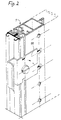
- the hollow profile rail 1 has on one narrow side a tongue 2 having a barb profile and on the opposite narrow side a longitudinal groove 5.
- a side wall lying flat against the narrow side of the hollow profile rail 1 and having a longitudinal groove is connected to the hollow profile rail 1.
- rows of holes 3 are provided in the longitudinal direction of the hollow profile rail, in whose holes hook-shaped tongues of different fittings engage, as shown in FIGS. 5, 6, 7 and 9.
- an undercut longitudinal groove 4 is further provided, in which engages a locking member 14, as shown in FIG. 10, by means of which the various fittings are clamped on the broad side or the broad sides of the hollow profile rail 1.
- the fitting 11 shown in FIG. 1 which has two hook tongues 111 engaging in the holes 3, two right-angled tongues 112 engaging in the longitudinal groove 4, serving to secure the position, is used to introduce the crossbar 142 of the locking member 17 serving elongated hole 113 and a groove 114 formed by right-angled bends into which the rear wall is inserted.
- the angular fitting 12 shown in FIG. 6 is used, the longer leg of which is designed in the same way as the longer leg of the fitting 11.
- the shorter leg has two bores 121 for receiving screws by means of which the rear wall is connected to the fitting 12.
- the shorter leg of the fitting 10 has an elongated hole 101 Inclusion of a holding member by means of which the screen is held on the fitting 10.
- the fittings 13 shown in FIG. 10 designed as suspension brackets, are used. These have double-bent hook tongues 131 on their upward-pointing leg and single-bent tongues 132 on the downward-pointing leg, which go into the holes 3 engage in the broad side of the hollow profile rail 1.
- the locking member 14 shown in FIG. 10 and used to clamp the fittings on the profile rails 1 and their locking has a clamping disc 141 and at a distance therefrom a cross bar 142 which engages in the longitudinal groove 4 of a broad side wall of the hollow profile rail 1 and after rotation around 90 ° engages behind the lateral bars of the longitudinal groove 4.
Landscapes
- Life Sciences & Earth Sciences (AREA)
- Engineering & Computer Science (AREA)
- Wood Science & Technology (AREA)
- Furniture Connections (AREA)
- Mutual Connection Of Rods And Tubes (AREA)
- Bidet-Like Cleaning Device And Other Flush Toilet Accessories (AREA)
- Fencing (AREA)
Claims (12)
Priority Applications (1)
| Application Number | Priority Date | Filing Date | Title |
|---|---|---|---|
| AT85100983T ATE48224T1 (de) | 1984-02-20 | 1985-01-31 | Schrank. |
Applications Claiming Priority (2)
| Application Number | Priority Date | Filing Date | Title |
|---|---|---|---|
| DE19848405083U DE8405083U1 (de) | 1984-02-20 | 1984-02-20 | Schrank |
| DE8405083U | 1984-02-20 |
Related Child Applications (1)
| Application Number | Title | Priority Date | Filing Date |
|---|---|---|---|
| EP89103038.9 Division-Into | 1989-02-22 |
Publications (2)
| Publication Number | Publication Date |
|---|---|
| EP0158016A1 EP0158016A1 (fr) | 1985-10-16 |
| EP0158016B1 true EP0158016B1 (fr) | 1989-11-29 |
Family
ID=6763765
Family Applications (1)
| Application Number | Title | Priority Date | Filing Date |
|---|---|---|---|
| EP85100983A Expired EP0158016B1 (fr) | 1984-02-20 | 1985-01-31 | Armoire |
Country Status (3)
| Country | Link |
|---|---|
| EP (1) | EP0158016B1 (fr) |
| AT (1) | ATE48224T1 (fr) |
| DE (3) | DE8405083U1 (fr) |
Families Citing this family (4)
| Publication number | Priority date | Publication date | Assignee | Title |
|---|---|---|---|---|
| DE3538402A1 (de) * | 1985-10-29 | 1987-04-30 | Andreas Moeslinger | Moebelsystem fuer den wohn- und arbeitsbereich |
| DE3804660A1 (de) * | 1988-02-15 | 1989-08-17 | Pan Brasilia Werk Gmbh | Schrank oder schrankwand |
| DE3834276A1 (de) * | 1988-10-08 | 1990-04-12 | Ver Spezialmoebel Verwalt | Moebeleinheit |
| DE8910709U1 (de) * | 1989-09-08 | 1991-01-17 | Waiko Möbelwerke GmbH & Co KG, 7071 Durlangen | Zerlegbare Schrankwand mit einem Profil aus Metall und Beschlagteilen |
Family Cites Families (4)
| Publication number | Priority date | Publication date | Assignee | Title |
|---|---|---|---|---|
| DE1779115A1 (de) * | 1968-07-09 | 1971-12-30 | Peter Ruppel Ladeneinrichtunge | Vorrichtung zum Aufhaengen von Vitrinen oder aehnlichen Gegenstaenden |
| FR2479671A1 (fr) * | 1980-04-04 | 1981-10-09 | Mullca | Meuble de rangement a structure metallique autoportante |
| DE3133456C2 (de) * | 1981-08-24 | 1984-10-31 | Knürr-Mechanik für die Elektronik AG, 8000 München | Möbelstück, insbesondere EDV- oder Labor-Mobiliar |
| GB2116833B (en) * | 1982-01-22 | 1986-02-26 | C O M Coop Operai Metallurg | Modular section for furniture assembly |
-
1984
- 1984-02-20 DE DE19848405083U patent/DE8405083U1/de not_active Expired
-
1985
- 1985-01-31 EP EP85100983A patent/EP0158016B1/fr not_active Expired
- 1985-01-31 DE DE8585100983T patent/DE3574448D1/de not_active Expired - Fee Related
- 1985-01-31 DE DE8989103038T patent/DE3578661D1/de not_active Expired - Fee Related
- 1985-01-31 AT AT85100983T patent/ATE48224T1/de not_active IP Right Cessation
Also Published As
| Publication number | Publication date |
|---|---|
| EP0158016A1 (fr) | 1985-10-16 |
| DE3574448D1 (de) | 1990-01-04 |
| ATE48224T1 (de) | 1989-12-15 |
| DE8405083U1 (de) | 1984-05-30 |
| DE3578661D1 (de) | 1990-08-16 |
Similar Documents
| Publication | Publication Date | Title |
|---|---|---|
| DE69326847T2 (de) | Tragärmezusammensetzung für regale | |
| DE69511676T2 (de) | Regalanordnung | |
| DE3021245A1 (de) | Display | |
| EP2434229A1 (fr) | Crochet de toit pour le montage de modules solaires sur des toits | |
| DE19647802C1 (de) | Montageschiene für einen Schaltschrank | |
| DE3325681A1 (de) | Elektrische apparatedosenbaugruppe und dafuer vorgesehener befestigungswinkel | |
| EP0158016B1 (fr) | Armoire | |
| EP0456104B1 (fr) | Support profilé pour un système d'agencement de magasins ou similaires | |
| WO2007101773A2 (fr) | Système de rail mural | |
| EP0732788A1 (fr) | Ensemble comprenant un support pour plafond et une console | |
| WO1999012657A1 (fr) | Paroi de cabine pour chaine de vernissage | |
| DE10134396C1 (de) | Bausatz zum Einsetzen eines Wandelementes in eine Wandöffnung einer doppelschaligen Ständerwand | |
| DE10044969A1 (de) | Wandprofilleiste | |
| EP0322403B1 (fr) | Armoire | |
| DE102007009667B4 (de) | Profilkonstruktion | |
| DE102005004654B4 (de) | Flexibles Präsentationssystem und Profilschiene hierfür | |
| WO1999035948A1 (fr) | Systeme de revetement pour cuve, de preference pour baignoire | |
| DE4421614A1 (de) | Fassadenverkleidung | |
| WO2000051465A1 (fr) | Dispositif permettant de fixer des rayons d'etagere | |
| DE69420798T2 (de) | Fernsprechverteilerleiste | |
| EP2084996A2 (fr) | Élément support et système pour la réalisation de stands d'exposition et semblables | |
| DE19931038C2 (de) | Verkleidungssystem für eine Wanne, vorzugsweise Badewanne | |
| EP1145666A1 (fr) | Etagère en particulier pour des bibliothèques | |
| DE102005056437B3 (de) | Raumteiler | |
| WO2023164734A1 (fr) | Agencement de montage |
Legal Events
| Date | Code | Title | Description |
|---|---|---|---|
| PUAI | Public reference made under article 153(3) epc to a published international application that has entered the european phase |
Free format text: ORIGINAL CODE: 0009012 |
|
| AK | Designated contracting states |
Designated state(s): AT DE FR GB NL SE |
|
| 17P | Request for examination filed |
Effective date: 19860415 |
|
| 17Q | First examination report despatched |
Effective date: 19870805 |
|
| GRAA | (expected) grant |
Free format text: ORIGINAL CODE: 0009210 |
|
| AK | Designated contracting states |
Kind code of ref document: B1 Designated state(s): AT DE FR GB NL SE |
|
| REF | Corresponds to: |
Ref document number: 48224 Country of ref document: AT Date of ref document: 19891215 Kind code of ref document: T |
|
| XX | Miscellaneous (additional remarks) |
Free format text: TEILANMELDUNG 89103038.9 EINGEREICHT AM 31/01/85. |
|
| REF | Corresponds to: |
Ref document number: 3574448 Country of ref document: DE Date of ref document: 19900104 |
|
| ET | Fr: translation filed | ||
| GBT | Gb: translation of ep patent filed (gb section 77(6)(a)/1977) | ||
| PLBE | No opposition filed within time limit |
Free format text: ORIGINAL CODE: 0009261 |
|
| PLBE | No opposition filed within time limit |
Free format text: ORIGINAL CODE: 0009261 |
|
| STAA | Information on the status of an ep patent application or granted ep patent |
Free format text: STATUS: NO OPPOSITION FILED WITHIN TIME LIMIT |
|
| 26N | No opposition filed | ||
| 26N | No opposition filed | ||
| PGFP | Annual fee paid to national office [announced via postgrant information from national office to epo] |
Ref country code: FR Payment date: 19940114 Year of fee payment: 10 |
|
| PGFP | Annual fee paid to national office [announced via postgrant information from national office to epo] |
Ref country code: AT Payment date: 19940117 Year of fee payment: 10 |
|
| PGFP | Annual fee paid to national office [announced via postgrant information from national office to epo] |
Ref country code: SE Payment date: 19940118 Year of fee payment: 10 Ref country code: GB Payment date: 19940118 Year of fee payment: 10 |
|
| PGFP | Annual fee paid to national office [announced via postgrant information from national office to epo] |
Ref country code: NL Payment date: 19940131 Year of fee payment: 10 |
|
| EAL | Se: european patent in force in sweden |
Ref document number: 85100983.7 |
|
| PG25 | Lapsed in a contracting state [announced via postgrant information from national office to epo] |
Ref country code: GB Effective date: 19950131 Ref country code: AT Effective date: 19950131 |
|
| PG25 | Lapsed in a contracting state [announced via postgrant information from national office to epo] |
Ref country code: SE Effective date: 19950201 |
|
| PG25 | Lapsed in a contracting state [announced via postgrant information from national office to epo] |
Ref country code: NL Effective date: 19950801 |
|
| GBPC | Gb: european patent ceased through non-payment of renewal fee |
Effective date: 19950131 |
|
| PG25 | Lapsed in a contracting state [announced via postgrant information from national office to epo] |
Ref country code: FR Effective date: 19950929 |
|
| NLV4 | Nl: lapsed or anulled due to non-payment of the annual fee |
Effective date: 19950801 |
|
| EUG | Se: european patent has lapsed |
Ref document number: 85100983.7 |
|
| REG | Reference to a national code |
Ref country code: FR Ref legal event code: ST |
|
| PGFP | Annual fee paid to national office [announced via postgrant information from national office to epo] |
Ref country code: DE Payment date: 19990225 Year of fee payment: 15 |
|
| PG25 | Lapsed in a contracting state [announced via postgrant information from national office to epo] |
Ref country code: DE Free format text: LAPSE BECAUSE OF NON-PAYMENT OF DUE FEES Effective date: 20001101 |