EP0158048A2 - Rührsysteme - Google Patents
Rührsysteme Download PDFInfo
- Publication number
- EP0158048A2 EP0158048A2 EP85101696A EP85101696A EP0158048A2 EP 0158048 A2 EP0158048 A2 EP 0158048A2 EP 85101696 A EP85101696 A EP 85101696A EP 85101696 A EP85101696 A EP 85101696A EP 0158048 A2 EP0158048 A2 EP 0158048A2
- Authority
- EP
- European Patent Office
- Prior art keywords
- impeller
- fibers
- blades
- leading edge
- edges
- Prior art date
- Legal status (The legal status is an assumption and is not a legal conclusion. Google has not performed a legal analysis and makes no representation as to the accuracy of the status listed.)
- Granted
Links
Images


Classifications
-
- B—PERFORMING OPERATIONS; TRANSPORTING
- B01—PHYSICAL OR CHEMICAL PROCESSES OR APPARATUS IN GENERAL
- B01F—MIXING, e.g. DISSOLVING, EMULSIFYING OR DISPERSING
- B01F27/00—Mixers with rotary stirring devices in fixed receptacles; Kneaders
- B01F27/80—Mixers with rotary stirring devices in fixed receptacles; Kneaders with stirrers rotating about a substantially vertical axis
- B01F27/91—Mixers with rotary stirring devices in fixed receptacles; Kneaders with stirrers rotating about a substantially vertical axis with propellers
-
- B—PERFORMING OPERATIONS; TRANSPORTING
- B01—PHYSICAL OR CHEMICAL PROCESSES OR APPARATUS IN GENERAL
- B01F—MIXING, e.g. DISSOLVING, EMULSIFYING OR DISPERSING
- B01F27/00—Mixers with rotary stirring devices in fixed receptacles; Kneaders
- B01F27/05—Stirrers
- B01F27/11—Stirrers characterised by the configuration of the stirrers
- B01F27/113—Propeller-shaped stirrers for producing an axial flow, e.g. shaped like a ship or aircraft propeller
-
- B—PERFORMING OPERATIONS; TRANSPORTING
- B01—PHYSICAL OR CHEMICAL PROCESSES OR APPARATUS IN GENERAL
- B01F—MIXING, e.g. DISSOLVING, EMULSIFYING OR DISPERSING
- B01F33/00—Other mixers; Mixing plants; Combinations of mixers
- B01F33/86—Mixing heads comprising a driven stirrer
- B01F33/862—Mixing heads comprising a driven stirrer the stirrer being provided with a surrounding stator
Definitions
- the present invention relates to mixing systems, and particularly to methods and apparatus for mixing and circulating liquids having fibers suspended therein.
- the present invention is especially suitable for use in mixing systems designed to treat waste water by the circulation of the water in tanks with an axial flow impeller in a draft tube.
- the invention is also suitable for use in other mixing applications liquid is circulated with an axial flow impeller.
- a system for mixing liquids in a tank in accordance with the invention utilizes an impeller which has opposite edges which respectively lead and trail each other as the impeller rotates.
- This system is operative to circulate the liquids through the tank along a flow path which extends axially of the impeller.
- the adhesion of fibers suspended in the liquid along the leading edge of the impeller is decreased, thereby preventing increased drag on the impeller due to the accumulation of the fibers on the leading edge as the impeller rotates.
- the adhesion is decreased by inclining the leading edge with respect to a radial line from the axis of the impeller sufficiently to be greater than the angle of repose of the fibers on the impeller.
- the angle of repose is that angle where the forces normal to the leading edge are sufficient to hold the fibers against the leading edge, considering the coefficient of friction of the surface of the impeller at the leading edge with respect to the fibers.
- the leading edge presents an inclined plane with an inclination larger than the angle of repose. Accordingly, the fibers are not held with sufficient force to maintain them on the leading edge and they continue to circulate with the liquid. This is in spite of the absence of any significant radial component of flow; the flow being essentially axial, particularly where the impeller is an axial flow impeller in a draft tube.
- the adhesion of the fibers along the leading edge may also be decreased by providing the portion of the impeller adjacent the leading edge with a surface of low coefficient of friction material, such a low coefficient of friction may be provided by polishing.
- Low coefficient of friction material is preferably provided by utilizing a plastic material presenting a low coefficient of friction to the fibers.
- a tank 10 which may be used for the mixing of liquids, such as waste water, having fibers in suspension.
- a draft tube 12 having a conical upper section 14 and a cylindrical lower section 16, is suspended from a beam 18 by posts 20. The lower section may also be diverging.
- the beam 18 also carries a drive assembly 22 including an electric motor 24 and gearing 26. Suitable bearings in the gearing section 26 rotatably support a drive shaft 28.
- An impeller 30 having a plurality of blade 32 is connected to a hub 34 which is connected to and driven by the drive shaft 28.
- the draft tube sections 14 and 16 define an impeller way 36.
- a sparge ring may be mounted below the impeller 30 in the lower section 16.
- air may be inducted through holes in the blades for sparging purposes as described in U.S. Patent No. 4,231,974.
- the operation and advantages of the impeller way 36 are described in U.S. Patent No. 3,477,382. Further information respecting the design of draft tube mixing systems may also be obtained from U.S. Patent No. 4,385,206.
- the impeller 34 is an axial flow impeller.
- Each of the blades have an airfoil shape and cause the liquid in the tank to be circulated through the draft tube, preferably downwardly when the system is used for mixing and aerating, although upward circulation may also be used. Vanes (not shown), for example as described in U.S. Patent No. 4,231,974, may be used to further direct the flow axially of the impeller.
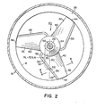
- the impeller has a plurality of blades, three blades 32 being used as shown in FIG. 2. Each of the blades is identical to the others. They are mounted 120° apart on the hub 34 and may be welded at their bases 35 to the hub 34.
- each blade 32 has an airfoil profile.
- the chord of the blade (CL) is measured between its leading edge 38 and its trailing edge 40.
- the blade has camber as measured between its midline 42 and chord.
- the blade also has twist, as shown in FIG. 3, in that the angle between the chord and the lower surface of the blade is greater at the base 35 of the blade than at the tip 44 thereof, and may be 10-18 0 greater.
- the camber may have a maximum length or value of from about 4 to 8 percent of the chord length.
- the location of the maximum chamber length may be from about 20% to about 60% of the chord length away from the leading edge 38 towards the trailing edge 40.
- the blade also has thickness between its upper and lower surfaces preferably from about 6 to 14 percent of the chord length.
- the width of the blade at the hub may be 22-28% of the chord length.
- the width of the blade at the tip may be 14-20% of the chord length.
- the tip chord angle (between the chord at the tip and the horizontal may be 5-25°.
- the blade may be constructed from a pair of plates 46 and 48, as shown in FIG. 4 which may be welded together near the leading and trailing edges.
- An insert 50 is provided in a portion extending approximately 10 percent of the length of each of the upper and lower surfaces from the leading to the trailing edges 38 and 40 of each blade 32. This insert is preferably a body of plastic materials which presents a surface having a low coefficient of friction.
- Ultra high molecular weight polyethlene (“UHMW”).
- UHMW ultra high molecular weight polyethlene
- TIVAR R Suitable material is available from Poly-Hi/Menasha Corp. under the trade name TIVAR R .
- Other material presenting a low coefficient of friction is suitable, for example a flouropolymer (such as known by the trade name Teflon). Ultra high molecular weight polyethelene is preferred.
- the tips 44 of the blades 32 have the shape of a sector of a circle and conform to the cylindrical inner periphery of the draft tube; extending to the inner periphery of the lower section 16, and separated therefrom only the necessary clearance to maintain manufacturing tolerances.
- the leading edge 38 is also longer than the trailing edge 40.
- the leading edge has an arcuate section 52 near the base end 35 and extends to a straight section 54.
- the trailing edge 40 is entirely straight.
- the arcuate section 52 is provided in order that the inclination of the leading edge can be sufficient so that the angle of repose of fibers which tend to accumulate on the leading edge is not reached.
- This angle of repose may be measured between the leading edge and radial lines extending from the axis 56 of the impeller (the center line of the shaft 28 and hub 34).
- the angle indicated as, 6, in FIG. 2 between a radial line 60 in a plane perpendicular to the axis 56 which intersects the leading edge 38 at a point 62, where the radial line has a length, R L , equal to 70 percent of the radius of the blade from the tip 44 to the axis 56 is 40°.
- This angle of inclination, 6, may be in a range from 20° to 60° depending upon the nature of the fibers which are suspended in the liquid being mixed and the coefficient of friction of the surface provided by the insert 50.
- a sufficient inclination angle 8 will suffice.
- the portion instead of providing an insert to present the portion of the surface at the leading edge with a low coefficient of friction, the portion may be polished.
- the low coefficient of friction material may be coated or otherwise bonded onto the surface.
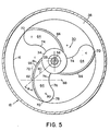
- the impeller 30 may be provided with blades 64 of a design shown in FIG. 5. These blades may be of airfoil profile their leading edges 66 are sectors of a circle.
- the angle of inclination, 6, as in FIG. 2 is measured at the intersection 62 of the radial line 60 of length 70% of the radius to the top 70 of the blade with the leading edge 66.
- the center of the sector is shown at 68 along a line perpendicular to tangent line 72.
- the trailing edge 74 of the blade is made up of two arcs, one of which 76 is a sector of a circle having its center at 68 and the other of which 78 is also a sector of a circle having its center 80 within the blade 64.
- the portion 81 of the blade adjacent the leading edge 66 may be provided by an insert of low coefficient of friction material, similar to the insert 50.
- the other techniques mentioned above, for providing low coefficient of friction in the surfaces of the portion 81, may alternatively be used.
Landscapes
- Chemical & Material Sciences (AREA)
- Chemical Kinetics & Catalysis (AREA)
- Engineering & Computer Science (AREA)
- Aviation & Aerospace Engineering (AREA)
- Mixers Of The Rotary Stirring Type (AREA)
- Aeration Devices For Treatment Of Activated Polluted Sludge (AREA)
- Processing And Handling Of Plastics And Other Materials For Molding In General (AREA)
Applications Claiming Priority (2)
| Application Number | Priority Date | Filing Date | Title |
|---|---|---|---|
| US59910984A | 1984-04-11 | 1984-04-11 | |
| US599109 | 1984-04-11 |
Publications (3)
| Publication Number | Publication Date |
|---|---|
| EP0158048A2 true EP0158048A2 (de) | 1985-10-16 |
| EP0158048A3 EP0158048A3 (en) | 1986-10-08 |
| EP0158048B1 EP0158048B1 (de) | 1990-10-31 |
Family
ID=24398251
Family Applications (1)
| Application Number | Title | Priority Date | Filing Date |
|---|---|---|---|
| EP85101696A Expired - Lifetime EP0158048B1 (de) | 1984-04-11 | 1985-02-15 | Rührsysteme |
Country Status (10)
| Country | Link |
|---|---|
| EP (1) | EP0158048B1 (de) |
| JP (1) | JPH0644981B2 (de) |
| KR (1) | KR920000538B1 (de) |
| AU (1) | AU569364B2 (de) |
| CA (1) | CA1249809A (de) |
| DE (1) | DE3580294D1 (de) |
| GB (1) | GB2157185A (de) |
| NZ (1) | NZ210861A (de) |
| PH (1) | PH22693A (de) |
| SG (1) | SG15392G (de) |
Cited By (10)
| Publication number | Priority date | Publication date | Assignee | Title |
|---|---|---|---|---|
| EP0469302A1 (de) * | 1990-07-26 | 1992-02-05 | General Signal Corporation | Mischungsrührer und Mischungssysteme zum Mischen von Flüssigkeiten und Flüssigkeitssuspensionen mit einem weiten Viskositätsbereich |
| EP0651672A4 (de) * | 1993-01-21 | 1995-03-21 | Gen Signal Corp | Erosionsbeständiger mischrotor. |
| BE1010118A3 (fr) * | 1996-04-05 | 1998-01-06 | Magotteaux Int | Helice de malaxeur. |
| KR100462245B1 (ko) * | 2002-07-15 | 2004-12-17 | 김승희 | 약품 용해장치 |
| EP1738863A1 (de) * | 2005-06-30 | 2007-01-03 | SPX Corporation | Mischrotor und Verfahren mit Unter- und Oberaussenblechen |
| EP1738861A1 (de) * | 2005-06-30 | 2007-01-03 | SPX Corporation | Mischrotor und Verfahren mit Schweissstellen |
| EP1738862A1 (de) * | 2005-06-30 | 2007-01-03 | SPX Corporation | Mischrotor und Verfahren mit vorgeformten Spitzenelementen |
| KR100852551B1 (ko) | 2007-02-07 | 2008-08-18 | 대우조선해양 주식회사 | 선박 탱크의 침전방지장치 |
| AU2006202877B2 (en) * | 2005-06-30 | 2010-12-02 | Spx Flow, Inc. | Mixing impeller and method with weld locations |
| CN111998757A (zh) * | 2020-08-28 | 2020-11-27 | 河海大学常州校区 | 一种粘性土水下休止角的测量装置及其方法 |
Families Citing this family (8)
| Publication number | Priority date | Publication date | Assignee | Title |
|---|---|---|---|---|
| GB8617569D0 (en) * | 1986-07-18 | 1986-08-28 | Davidson J F | Impellers |
| FR2784311B1 (fr) * | 1998-10-09 | 2000-12-08 | Air Liquide | Dispositif d'agitation d'un liquide dans un reacteur et d'injection d'un gaz dans ce liquide |
| JP2011240230A (ja) * | 2010-05-17 | 2011-12-01 | Hitachi Plant Technologies Ltd | 攪拌機の運転方法 |
| JP2015205250A (ja) * | 2014-04-22 | 2015-11-19 | 日立造船株式会社 | 攪拌装置 |
| CN104959066B (zh) * | 2015-06-12 | 2019-01-18 | 中国核电工程有限公司 | 一种用于核废物处理的搅拌桨及搅拌装置 |
| CN106422866B (zh) * | 2016-09-27 | 2018-09-28 | 嘉兴晟源工业设计有限公司 | 一种具有搅拌和罐装功能的一体式药粉搅拌机 |
| WO2019073835A1 (ja) * | 2017-10-12 | 2019-04-18 | 東レ株式会社 | メディア型分散機および液状分散物の製造方法 |
| KR102527653B1 (ko) * | 2021-01-13 | 2023-05-02 | 오브맘코리아컴퍼니 주식회사 | 천연 5종 컴플렉스 항균 원료 조성물 및 그 제조 장치 |
Family Cites Families (15)
| Publication number | Priority date | Publication date | Assignee | Title |
|---|---|---|---|---|
| GB296247A (en) * | 1928-01-09 | 1928-08-30 | Pfaudler Co Inc | Improvements in or relating to rotary agitators |
| GB1026384A (en) * | 1962-06-05 | 1966-04-20 | Activated Sludge Ltd | Improvements in or relating to aerators |
| US3367423A (en) * | 1966-06-13 | 1968-02-06 | Cornelius W. Van Ranst | Propeller |
| SE385819B (sv) * | 1972-11-13 | 1976-07-26 | S Hjorth | Propeller |
| US3870195A (en) * | 1973-04-26 | 1975-03-11 | Saco Lowell Corp | Apparatus for and method of feeding bobbin tubes |
| FR2315001A1 (fr) * | 1975-06-18 | 1977-01-14 | Entat Marcel | Procede de realisation de pales d'helices et pales d'helices perfectionnees obtenues par la mise en oeuvre de ce procede |
| JPS556081U (de) * | 1978-06-29 | 1980-01-16 | ||
| US4231974A (en) * | 1979-01-29 | 1980-11-04 | General Signal Corporation | Fluids mixing apparatus |
| JPS5639196U (de) * | 1979-09-04 | 1981-04-13 | ||
| US4378165A (en) * | 1980-12-30 | 1983-03-29 | General Signal Corporation | Draft tube apparatus |
| US4468130A (en) * | 1981-11-04 | 1984-08-28 | General Signal Corp. | Mixing apparatus |
| EP0079396A1 (de) * | 1981-11-12 | 1983-05-25 | Hans Kimmel | Flügel für ein rotierendes Misch- und Rührwerkzeug |
| US4480796A (en) * | 1982-01-25 | 1984-11-06 | Beloit Corporation | Pulping apparatus including improved rotor |
| GB2143440A (en) * | 1983-07-21 | 1985-02-13 | Morton Robert Dg Ltd | Mixers |
| JPS6119794U (ja) * | 1984-07-10 | 1986-02-05 | 石川島播磨重工業株式会社 | 高速増殖炉 |
-
1985
- 1985-01-11 AU AU37606/85A patent/AU569364B2/en not_active Ceased
- 1985-01-17 NZ NZ210861A patent/NZ210861A/en unknown
- 1985-01-21 JP JP60008929A patent/JPH0644981B2/ja not_active Expired - Lifetime
- 1985-02-05 CA CA000473601A patent/CA1249809A/en not_active Expired
- 1985-02-15 DE DE8585101696T patent/DE3580294D1/de not_active Expired - Lifetime
- 1985-02-15 EP EP85101696A patent/EP0158048B1/de not_active Expired - Lifetime
- 1985-02-20 PH PH31886A patent/PH22693A/en unknown
- 1985-02-21 GB GB08504508A patent/GB2157185A/en not_active Withdrawn
- 1985-02-22 KR KR1019850001122A patent/KR920000538B1/ko not_active Expired
-
1992
- 1992-02-18 SG SG153/92A patent/SG15392G/en unknown
Cited By (12)
| Publication number | Priority date | Publication date | Assignee | Title |
|---|---|---|---|---|
| EP0469302A1 (de) * | 1990-07-26 | 1992-02-05 | General Signal Corporation | Mischungsrührer und Mischungssysteme zum Mischen von Flüssigkeiten und Flüssigkeitssuspensionen mit einem weiten Viskositätsbereich |
| EP0651672A4 (de) * | 1993-01-21 | 1995-03-21 | Gen Signal Corp | Erosionsbeständiger mischrotor. |
| BE1010118A3 (fr) * | 1996-04-05 | 1998-01-06 | Magotteaux Int | Helice de malaxeur. |
| KR100462245B1 (ko) * | 2002-07-15 | 2004-12-17 | 김승희 | 약품 용해장치 |
| EP1738863A1 (de) * | 2005-06-30 | 2007-01-03 | SPX Corporation | Mischrotor und Verfahren mit Unter- und Oberaussenblechen |
| EP1738861A1 (de) * | 2005-06-30 | 2007-01-03 | SPX Corporation | Mischrotor und Verfahren mit Schweissstellen |
| EP1738862A1 (de) * | 2005-06-30 | 2007-01-03 | SPX Corporation | Mischrotor und Verfahren mit vorgeformten Spitzenelementen |
| US7481573B2 (en) | 2005-06-30 | 2009-01-27 | Spx Corporation | Mixing impeller with pre-shaped tip elements |
| AU2006202877B2 (en) * | 2005-06-30 | 2010-12-02 | Spx Flow, Inc. | Mixing impeller and method with weld locations |
| KR100852551B1 (ko) | 2007-02-07 | 2008-08-18 | 대우조선해양 주식회사 | 선박 탱크의 침전방지장치 |
| CN111998757A (zh) * | 2020-08-28 | 2020-11-27 | 河海大学常州校区 | 一种粘性土水下休止角的测量装置及其方法 |
| CN111998757B (zh) * | 2020-08-28 | 2022-06-14 | 河海大学常州校区 | 一种粘性土水下休止角的测量装置及其方法 |
Also Published As
| Publication number | Publication date |
|---|---|
| PH22693A (en) | 1988-11-14 |
| AU3760685A (en) | 1985-10-17 |
| EP0158048B1 (de) | 1990-10-31 |
| GB2157185A (en) | 1985-10-23 |
| EP0158048A3 (en) | 1986-10-08 |
| GB8504508D0 (en) | 1985-03-27 |
| CA1249809A (en) | 1989-02-07 |
| NZ210861A (en) | 1986-09-10 |
| DE3580294D1 (en) | 1990-12-06 |
| AU569364B2 (en) | 1988-01-28 |
| KR850007219A (ko) | 1985-12-02 |
| JPH0644981B2 (ja) | 1994-06-15 |
| KR920000538B1 (ko) | 1992-01-16 |
| SG15392G (en) | 1992-04-16 |
| JPS60227821A (ja) | 1985-11-13 |
Similar Documents
| Publication | Publication Date | Title |
|---|---|---|
| US4571090A (en) | Mixing systems | |
| EP0158048A2 (de) | Rührsysteme | |
| US3416729A (en) | Liquid aerator | |
| EP0078660B1 (de) | Mischrotor mit Axialflusswirkung | |
| US4468358A (en) | Apparatus for mixing air and liquid | |
| US4444510A (en) | Stirrer, having substantially triangular, radial blades, rising toward the circumference | |
| EP0880993B1 (de) | Rührschaufelanordnung mit asymmetrisch-konkaven Schaufeln | |
| US4540528A (en) | Apparatus for mixing gas and liquid | |
| US4231974A (en) | Fluids mixing apparatus | |
| US4802771A (en) | Mixing apparatus | |
| AU8026791A (en) | Mixing impellers and impeller systems for mixing and blending liquids and liquid suspensions having a wide range of viscosities | |
| US8220986B2 (en) | High efficiency mixer-impeller | |
| US5951162A (en) | Mixing impellers and impeller systems for mixing and blending liquids and liquid suspensions having efficient power consumption characteristics | |
| US5681146A (en) | Low head pumping system for fish farms | |
| US5525269A (en) | Impeller tiplets for improving gas to liquid mass transfer efficiency in a draft tube submerged turbine mixer/aerator | |
| US5052892A (en) | High efficiency mixer impeller | |
| US4519715A (en) | Propeller | |
| US2063301A (en) | Aerator | |
| US12390773B2 (en) | Gas dispersion system | |
| CN1005757B (zh) | 拌混系统 | |
| JP3239171B2 (ja) | 攪拌曝気装置における軸流インペラ | |
| JP3239170B2 (ja) | 攪拌曝気装置における軸流インペラ | |
| US4615623A (en) | Impeller for mixing tanks | |
| CA1207750A (en) | Propeller | |
| CA1073125A (en) | Flotation machine with mixing and aeration impeller and method |
Legal Events
| Date | Code | Title | Description |
|---|---|---|---|
| PUAI | Public reference made under article 153(3) epc to a published international application that has entered the european phase |
Free format text: ORIGINAL CODE: 0009012 |
|
| AK | Designated contracting states |
Designated state(s): DE FR GB IT NL SE |
|
| PUAL | Search report despatched |
Free format text: ORIGINAL CODE: 0009013 |
|
| AK | Designated contracting states |
Kind code of ref document: A3 Designated state(s): DE FR GB IT NL SE |
|
| 17P | Request for examination filed |
Effective date: 19870129 |
|
| 17Q | First examination report despatched |
Effective date: 19871203 |
|
| GRAA | (expected) grant |
Free format text: ORIGINAL CODE: 0009210 |
|
| ITF | It: translation for a ep patent filed | ||
| AK | Designated contracting states |
Kind code of ref document: B1 Designated state(s): DE FR GB IT NL SE |
|
| REF | Corresponds to: |
Ref document number: 3580294 Country of ref document: DE Date of ref document: 19901206 |
|
| ET | Fr: translation filed | ||
| ITTA | It: last paid annual fee | ||
| PLBE | No opposition filed within time limit |
Free format text: ORIGINAL CODE: 0009261 |
|
| STAA | Information on the status of an ep patent application or granted ep patent |
Free format text: STATUS: NO OPPOSITION FILED WITHIN TIME LIMIT |
|
| 26N | No opposition filed | ||
| EAL | Se: european patent in force in sweden |
Ref document number: 85101696.4 |
|
| PGFP | Annual fee paid to national office [announced via postgrant information from national office to epo] |
Ref country code: FR Payment date: 19960117 Year of fee payment: 12 |
|
| PGFP | Annual fee paid to national office [announced via postgrant information from national office to epo] |
Ref country code: SE Payment date: 19960122 Year of fee payment: 12 |
|
| PGFP | Annual fee paid to national office [announced via postgrant information from national office to epo] |
Ref country code: NL Payment date: 19960125 Year of fee payment: 12 |
|
| PGFP | Annual fee paid to national office [announced via postgrant information from national office to epo] |
Ref country code: DE Payment date: 19960130 Year of fee payment: 12 |
|
| PG25 | Lapsed in a contracting state [announced via postgrant information from national office to epo] |
Ref country code: SE Effective date: 19970216 |
|
| PG25 | Lapsed in a contracting state [announced via postgrant information from national office to epo] |
Ref country code: NL Effective date: 19970901 |
|
| PG25 | Lapsed in a contracting state [announced via postgrant information from national office to epo] |
Ref country code: FR Effective date: 19971030 |
|
| PG25 | Lapsed in a contracting state [announced via postgrant information from national office to epo] |
Ref country code: DE Effective date: 19971101 |
|
| EUG | Se: european patent has lapsed |
Ref document number: 85101696.4 |
|
| NLV4 | Nl: lapsed or anulled due to non-payment of the annual fee |
Effective date: 19970901 |
|
| REG | Reference to a national code |
Ref country code: FR Ref legal event code: ST |
|
| REG | Reference to a national code |
Ref country code: GB Ref legal event code: IF02 |
|
| PGFP | Annual fee paid to national office [announced via postgrant information from national office to epo] |
Ref country code: GB Payment date: 20020501 Year of fee payment: 18 |
|
| PG25 | Lapsed in a contracting state [announced via postgrant information from national office to epo] |
Ref country code: GB Free format text: LAPSE BECAUSE OF NON-PAYMENT OF DUE FEES Effective date: 20030215 |
|
| GBPC | Gb: european patent ceased through non-payment of renewal fee |