EP0158142A2 - Dispositif pour déterminer et/ou maintenir constant le rapport de mélange d'un mélange de liquide - Google Patents
Dispositif pour déterminer et/ou maintenir constant le rapport de mélange d'un mélange de liquide Download PDFInfo
- Publication number
- EP0158142A2 EP0158142A2 EP85102852A EP85102852A EP0158142A2 EP 0158142 A2 EP0158142 A2 EP 0158142A2 EP 85102852 A EP85102852 A EP 85102852A EP 85102852 A EP85102852 A EP 85102852A EP 0158142 A2 EP0158142 A2 EP 0158142A2
- Authority
- EP
- European Patent Office
- Prior art keywords
- switching
- detection fields
- diaphragm
- switching device
- floating body
- Prior art date
- Legal status (The legal status is an assumption and is not a legal conclusion. Google has not performed a legal analysis and makes no representation as to the accuracy of the status listed.)
- Granted
Links
Images
Classifications
-
- B—PERFORMING OPERATIONS; TRANSPORTING
- B41—PRINTING; LINING MACHINES; TYPEWRITERS; STAMPS
- B41F—PRINTING MACHINES OR PRESSES
- B41F7/00—Rotary lithographic machines
- B41F7/20—Details
- B41F7/24—Damping devices
- B41F7/26—Damping devices using transfer rollers
-
- B—PERFORMING OPERATIONS; TRANSPORTING
- B41—PRINTING; LINING MACHINES; TYPEWRITERS; STAMPS
- B41F—PRINTING MACHINES OR PRESSES
- B41F33/00—Indicating, counting, warning, control or safety devices
-
- G—PHYSICS
- G01—MEASURING; TESTING
- G01N—INVESTIGATING OR ANALYSING MATERIALS BY DETERMINING THEIR CHEMICAL OR PHYSICAL PROPERTIES
- G01N9/00—Investigating density or specific gravity of materials; Analysing materials by determining density or specific gravity
- G01N9/10—Investigating density or specific gravity of materials; Analysing materials by determining density or specific gravity by observing bodies wholly or partially immersed in fluid materials
- G01N9/12—Investigating density or specific gravity of materials; Analysing materials by determining density or specific gravity by observing bodies wholly or partially immersed in fluid materials by observing the depth of immersion of the bodies, e.g. hydrometers
- G01N9/18—Special adaptations for indicating, recording, or control
-
- G—PHYSICS
- G05—CONTROLLING; REGULATING
- G05D—SYSTEMS FOR CONTROLLING OR REGULATING NON-ELECTRIC VARIABLES
- G05D21/00—Control of chemical or physico-chemical variables, e.g. pH value
- G05D21/02—Control of chemical or physico-chemical variables, e.g. pH value characterised by the use of electric means
-
- Y—GENERAL TAGGING OF NEW TECHNOLOGICAL DEVELOPMENTS; GENERAL TAGGING OF CROSS-SECTIONAL TECHNOLOGIES SPANNING OVER SEVERAL SECTIONS OF THE IPC; TECHNICAL SUBJECTS COVERED BY FORMER USPC CROSS-REFERENCE ART COLLECTIONS [XRACs] AND DIGESTS
- Y10—TECHNICAL SUBJECTS COVERED BY FORMER USPC
- Y10T—TECHNICAL SUBJECTS COVERED BY FORMER US CLASSIFICATION
- Y10T137/00—Fluid handling
- Y10T137/2496—Self-proportioning or correlating systems
- Y10T137/2499—Mixture condition maintaining or sensing
- Y10T137/2504—By specific gravity
Definitions
- the invention relates to a device for determining and / or maintaining the mixing ratio of a liquid mixture, in particular for determining and maintaining the alcohol concentration of the dampening liquid used in the offset printing process, with a device in a vessel which is provided with an inlet and an overflow and is arranged in a liquid circuit. recorded floating body, which interacts with a switching device which can be activated as a function of its immersion depth.
- a valve is actuated mechanically by means of the floating body, which controls an admixing line for admixing alcohol.
- the valve opening and closing forces to be overcome by the floating body constant maintenance can only be achieved within a very wide range.
- Another disadvantage of this known arrangement is the fact that it is not possible to display and store the current alcohol concentration values. It is true that the use of proximity initiators assigned to the float has already been used to control the valve of the admixture line. There are no opening and closing forces to be overcome by the float. However, it is also not possible to display and save the current alcohol concentration values here.
- the mechanical fixation of the proximity initiators required fixes them to a very specific value. If the desired concentration changes, the proximity initiators must be adjusted. This results in a very high adjustment effort, since the adjustment of the proximity initiators is very difficult.
- an aperture can be actuated by means of the floating body, which is provided with detection fields arranged one above the other and can be scanned in a contact-free manner by means of a vertically arranged scanning device, the output of which lies at the actual value output of the switching device, which in addition to the actual value input is a setpoint input and has at least one switching output.
- the immersion depth of the float is a function of the specific weight of the rivers fed to the vessel liquidity.
- the specific weight of the liquid depends on the concentration of the individual components, in the case of a dampening solution, for example, on the alcohol concentration. As a rule, this dependency is not linear.
- the aperture is therefore advantageously designed such that the detection fields arranged one above the other are assigned to adjacent, equally wide areas of the concentrate of a liquid and that the height of the detection fields is in each case the change in the immersion depth of the float when the concentration changes between the limits of the respectively assigned area corresponds. This practically linearizes the above-mentioned relationship between specific weight and concentration.
- a further expedient further development of the higher-level measures may consist in the floating body having a diving body which is connected to the diaphragm by means of a rod fastened thereon which has a constant length over its entire length, which corresponds to at least the entire height of all the detection fields arranged one above the other.
- a rod fastened thereon which has a constant length over its entire length, which corresponds to at least the entire height of all the detection fields arranged one above the other.
- only the rod emerges more or less from the liquid. Due to the constant diameter, however, there are simple relationships between the buoyancy and the specific weight and thus the concentration sought.
- the immersion body attached to the rod nevertheless ensures a high overall buoyancy and therefore a high level of accuracy.
- a particularly simple and therefore particularly preferred Execution can consist in that the scanning device has at least one stationary arranged, preferably designed as a diode, optical transmitter and at least one, opposite this, preferably designed as a photocell, optical receiver, and that the aperture is designed as an optical aperture, which in intervenes in the space between the transmitter and receiver.
- the use of light for scanning the diaphragm advantageously results in a simple design and still ensures high accuracy.
- the detection fields can expediently be designed in the form of the so-called Gray code. This results in a very precise and. nevertheless very space-saving arrangement.
- the non-printing areas of the printing plate are known to be moistened with a dampening solution which, in addition to water, essentially contains alcohol and possibly a small amount of acid and / or alkali. It is desirable to keep the mixing ratio of these components as constant as possible.
- a dampening solution which, in addition to water, essentially contains alcohol and possibly a small amount of acid and / or alkali. It is desirable to keep the mixing ratio of these components as constant as possible.
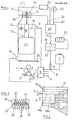
- 1 shows an offset printing press 1 is indicated, the plate cylinder 2 is supplied by means of an inking unit 3 with color and by means of a dampening unit 4 with a Feuchtm tt l p l.
- the dampening unit 4 is provided with a tub 5 which can be acted upon with dampening solution.
- the dampening solution is circulated via a treatment system 6, in which the consumption of dampening solution is also supplemented.
- the treatment plant 5 is provided with the inputs 6 assigned to the individual components.
- the input 6 assigned to the alcohol is connected to a tank 7 and can be opened and closed by means of a valve 8, to which an actuating motor 9 designed as a solenoid is assigned.
- the device for keeping the alcohol content constant consists of a vessel 12, which is arranged in the circulation circuit leading over the treatment plant 5 and is provided upstream here with respect to the treatment plant 5 and is provided with a bottom inlet 10 and an overflow 11 arranged at a higher level, in which a float 13 is received is.
- An aperture 14 is fastened to the floating body 13 and is scanned by a stationary scanning device 15.
- the aperture 14, as can best be seen from FIG. 2, is provided with detection fields 16 arranged one above the other, each of which has a specific concentration are assigned.
- the scanning device 15 is arranged and designed so that a detection field 16 can be detected in each case. Which field is covered depends on. how deep the float 13 is immersed in the liquid contained in the vessel 12.
- This immersion depth in turn depends on the specific weight of the liquid, since the buoyancy force acting on the floating body, ie the weight of the displaced liquid, must be in balance with the total weight of the floating body 13 and the aperture 14. This is a measure of the concentration of alcohol, since the specific gravity to the dampening solution by a known function with the Al koho - changes lkonzentration.
- Each detection field 16 therefore contains information readable by the scanning device 15 about the alcohol concentration corresponding to the associated immersion depth of the floating body 13. The values obtained at the output of the scanning device 15 accordingly indicate the actual alcohol content and can be used directly as actual values for controlling the alcohol concentration.
- the floating body 13 is provided with a diving body 17 which never emerges from the liquid in the vessel 12 and a rod 18 which projects upwards therefrom and which penetrates the liquid level 19 in order to achieve a high buoyancy force.
- the aperture 14 is attached to the rod 18.
- the diameter of the rod 18 is comparatively small compared to the diameter of the immersion body 17 and is constant over the entire height of the rod 18. This results in simple geometric relationships, including those dependent on the immersion depth, for determining the alcohol content.
- the length of the rod 18 corresponds at least to the total height of the diaphragm 14, that is to say the total height of all detection fields 15 arranged one above the other.
- the desired depth of the immersion body 17 can be adjusted simply by weighting etc.
- the height of the detection fields 16 arranged one above the other corresponds to a range of the alcohol concentration corresponding to the desired constant maintenance accuracy. In practice it is desirable to keep the alcohol concentration constant within a range of 0.5%.
- the height of the detection fields 16 therefore corresponds to the change in the immersion depth of the floating body 13 when the alcohol concentration changes by 0.5% in each case. If the curve indicating the dependence of the immersion depth on the alcohol concentration was linear, all detection fields 16 would have the same height. However, the curve mentioned is not linear. This non-linearity can be compensated for by correspondingly varying the height of individual detection fields, as is indicated in FIG. 2, for example, using the detection fields 16a and 16b.
- the detection field 16a has a comparatively small height a.
- the detection field 16b has a comparatively large height. This means that the of the floating body 13 changes comparatively strongly over the assigned alcohol concentration range. This trick in terms of varying the height of the individual detection fields can therefore advantageously be used to linearize the alcohol curve.
- the aperture 14 is scanned contactlessly in the region of the scanning device 15.
- the aperture 14 should be designed as an optical aperture in which the intensity of the light passing through it is recorded as a measure of the alcohol concentration.
- the scanning device 15 is provided with at least one optical transmitter 20, for example in the form of a diode, and with at least one optical receiver 21, for example in the form of a photocell.
- the detection fields 16 are designed in such a way that they let light through at some points and not at some points, from which the desired information can be obtained.
- the detection fields 2, as indicated in FIG. 2 are designed in accordance with the so-called Gray code, a code width of 6 bits being provided. Accordingly, each detection field 16 is divided into 6 areas lying next to one another, which are translucent or opaque according to the legality of the Gray code. In FIG. 2, for example, the hatched areas are said to be opaque, the remaining areas are to be translucent.
- the scanning device 15 is provided with 6 transmitters 20 and 6 receivers 21 arranged next to one another, each of which is assigned to a region of the six regions of the detection fields 16.
- These juxtaposed transmitters 20 and receivers 21 in the form of diodes or photocells are received on a carrier 22 which is provided with a slot 23 bridging the distance between the transmitters and the receivers, into which the aperture 14 to be scanned engages.
- the panel 14 can consist, for example, of a card made of transparent material printed in accordance with the Gray code and accommodated in a frame 24 which can be guided in the slot 23.
- the carrier 22 is arranged stationary with respect to the vessel. For this purpose, as indicated in FIG. 1, the carrier 22 can simply be connected to the vessel 12, which in turn is fixed to a suitable stationary frame 25.
- the values recorded by the contactless scanning of the diaphragm 14 by means of the scanning device 15 are compared as actual values with / a target value, with a command to open or close the value from a possible difference between the actual value and the target value Alcohol input 6 associated valve 8 is formed.
- a switching device 28 provided with an actual value input 26 and a target value input 27 is provided, the actual value input 26 of which is located at the output of the scanning device 15 and the target value Value input 27 is connected to a setpoint generator.
- the target value transmitter 29 is expediently adjustable.
- the photocells forming the receivers 21 of the scanning device 15 act as photoelectric converters, which emit an electrical quantity corresponding to the incident light.
- the adjustable setpoint generator 29 can therefore be simply configured as a potentiometer.
- the transmitters 20 can be in continuous operation.
- the switching device 28 interrogates the receivers 21 simultaneously or in succession at time intervals.
- a control unit 30 which can be switched on and off manually is provided for activating and controlling the scanning device 15 and the switching device 28. It would be conceivable to switch the control unit 30 into the switch device 28 to integrate.
- the servomotor 9 assigned to the valve 8 here in the form of a contactor, is actuated in such a way that the valve 8 is kept open in the event of a lack of alcohol and is kept in the closed position when there is an excess of alcohol.
- the receiver 21 is queried at short time intervals.
- the switching device 28 is followed by an integrator 31 with a memory 32.
- the queried values are stored in the memory 32 and then integrated on.
- the integrated values result in an average value which is used as a control signal for the servomotor 9.
- these values are displayed on a digital display device 33 which can be controlled by the integrator 31.
- the coding of the aperture 16 and the design of the scanning device 15, each with a transmitter-receiver unit provided per bit, automatically digitize the recorded values, which facilitates digital display. It would be conceivable to integrate the integrator 31 and / or the display device 33 which can be controlled thereby and / or the servomotor 9 which can be controlled thereby in the switching device 28.
Landscapes
- Engineering & Computer Science (AREA)
- General Physics & Mathematics (AREA)
- Physics & Mathematics (AREA)
- General Health & Medical Sciences (AREA)
- Immunology (AREA)
- Chemical & Material Sciences (AREA)
- Analytical Chemistry (AREA)
- Biochemistry (AREA)
- Health & Medical Sciences (AREA)
- Mechanical Engineering (AREA)
- Life Sciences & Earth Sciences (AREA)
- Pathology (AREA)
- Automation & Control Theory (AREA)
- Investigating Or Analysing Materials By Optical Means (AREA)
- Accessories For Mixers (AREA)
- Control Of Non-Electrical Variables (AREA)
- Level Indicators Using A Float (AREA)
- Inking, Control Or Cleaning Of Printing Machines (AREA)
Priority Applications (1)
| Application Number | Priority Date | Filing Date | Title |
|---|---|---|---|
| AT85102852T ATE51719T1 (de) | 1984-03-27 | 1985-03-12 | Vorrichtung zur bestimmung und/oder konstanthaltung des mischungsverhaeltnisses einer fluessigkeitsmischung. |
Applications Claiming Priority (2)
| Application Number | Priority Date | Filing Date | Title |
|---|---|---|---|
| DE3411163A DE3411163C1 (de) | 1984-03-27 | 1984-03-27 | Vorrichtung zur Bestimmung und/oder Konstanthaltung des Mischungsverhältnisses einer Flüssigkeitsmischung |
| DE3411163 | 1984-03-27 |
Publications (3)
| Publication Number | Publication Date |
|---|---|
| EP0158142A2 true EP0158142A2 (fr) | 1985-10-16 |
| EP0158142A3 EP0158142A3 (en) | 1986-10-08 |
| EP0158142B1 EP0158142B1 (fr) | 1990-04-04 |
Family
ID=6231688
Family Applications (1)
| Application Number | Title | Priority Date | Filing Date |
|---|---|---|---|
| EP19850102852 Expired - Lifetime EP0158142B1 (fr) | 1984-03-27 | 1985-03-12 | Dispositif pour déterminer et/ou maintenir constant le rapport de mélange d'un mélange de liquide |
Country Status (5)
| Country | Link |
|---|---|
| US (1) | US4601306A (fr) |
| EP (1) | EP0158142B1 (fr) |
| JP (1) | JPS60238912A (fr) |
| AT (1) | ATE51719T1 (fr) |
| DE (2) | DE3411163C1 (fr) |
Cited By (2)
| Publication number | Priority date | Publication date | Assignee | Title |
|---|---|---|---|---|
| EP0693721A1 (fr) | 1994-07-22 | 1996-01-24 | Baldwin-Gegenheimer GmbH | Méthode et appareil pour mesurer et stabiliser la partie proportionnelle d'un composant liquide |
| CN110006735A (zh) * | 2019-06-03 | 2019-07-12 | 湖南乐准智芯生物科技有限公司 | 一种混匀状态识别方法及系统 |
Families Citing this family (9)
| Publication number | Priority date | Publication date | Assignee | Title |
|---|---|---|---|---|
| US4899774A (en) * | 1989-05-22 | 1990-02-13 | Keller Jr R Davidson | Fluidic density control for chlor alkali cells |
| US5551468A (en) * | 1994-01-04 | 1996-09-03 | Lemke; Chris A. | Fluidic density control for chlor alkali cells |
| DE19546971A1 (de) | 1995-12-15 | 1997-06-19 | Baldwin Gegenheimer Gmbh | Vorrichtung einer Druckmaschine |
| DE19802224C1 (de) * | 1998-01-22 | 1999-05-20 | Sita Messtechnik Gmbh | Verfahren und Vorrichtung zum Messen oder zum Messen und Einstellen der Konzentration einer Substanz in einer Flüssigkeit |
| SE9802690D0 (sv) * | 1998-08-07 | 1998-08-07 | Astra Ab | Mixing apparatus |
| DE102007012443A1 (de) * | 2007-03-15 | 2008-09-18 | Lindauer Dornier Gesellschaft Mit Beschränkter Haftung | Einrichtung zum Regeln der Dichte eines Flüssigkeitsgemisches und Verwendung der Einrichtung |
| CN107727197A (zh) * | 2017-10-11 | 2018-02-23 | 镇江乐科信息科技有限公司 | 一种基于信息技术的安全检测系统 |
| CN109433828A (zh) * | 2018-10-31 | 2019-03-08 | 攀钢集团攀枝花钢钒有限公司 | 一种湿平整自动配液的控制方法 |
| CN110801743B (zh) * | 2019-10-30 | 2021-10-01 | 遵义医学院附属医院 | 一种多梯度酒精可定量配制瓶 |
Family Cites Families (9)
| Publication number | Priority date | Publication date | Assignee | Title |
|---|---|---|---|---|
| US2543522A (en) * | 1945-06-08 | 1951-02-27 | Samuel J Cohen | Apparatus for proportioning liquids |
| FR1447071A (fr) * | 1964-10-08 | 1966-07-22 | Bizerba Werke Kraut Kg Wilh | Aéromètre pour la détermination du poids spécifique des liquides |
| DE2049195A1 (de) * | 1970-10-07 | 1972-04-27 | Willi Fricker Kupferschmiede U | Verfahren zur Regelung des Prozentgehaltes an Alkohol für Schnapsbrennereien |
| US3947356A (en) * | 1972-11-20 | 1976-03-30 | Maschinenfabrik Wifag | Arrangement for regulating the moistening solution mixture in a moistening solution preparation plant for an offset printing press |
| JPS512459A (fr) * | 1974-06-25 | 1976-01-10 | Nippon Soken | |
| US4131019A (en) * | 1975-04-10 | 1978-12-26 | Cominco Ltd. | Method and apparatus for measuring specific gravity of liquids in process streams |
| JPS5539059A (en) * | 1978-09-13 | 1980-03-18 | Japan Storage Battery Co Ltd | Liquid specific gravity detector |
| US4398554A (en) * | 1981-04-09 | 1983-08-16 | Nihon Den-Netsu Keiki Co., Ltd. | Flux control device |
| US4474204A (en) * | 1983-07-22 | 1984-10-02 | The Western Company Of North America | Delivery and metering device control system |
-
1984
- 1984-03-27 DE DE3411163A patent/DE3411163C1/de not_active Expired
-
1985
- 1985-03-08 US US06/709,958 patent/US4601306A/en not_active Expired - Lifetime
- 1985-03-12 AT AT85102852T patent/ATE51719T1/de not_active IP Right Cessation
- 1985-03-12 EP EP19850102852 patent/EP0158142B1/fr not_active Expired - Lifetime
- 1985-03-12 DE DE8585102852T patent/DE3577014D1/de not_active Expired - Fee Related
- 1985-03-26 JP JP60063186A patent/JPS60238912A/ja active Granted
Cited By (2)
| Publication number | Priority date | Publication date | Assignee | Title |
|---|---|---|---|---|
| EP0693721A1 (fr) | 1994-07-22 | 1996-01-24 | Baldwin-Gegenheimer GmbH | Méthode et appareil pour mesurer et stabiliser la partie proportionnelle d'un composant liquide |
| CN110006735A (zh) * | 2019-06-03 | 2019-07-12 | 湖南乐准智芯生物科技有限公司 | 一种混匀状态识别方法及系统 |
Also Published As
| Publication number | Publication date |
|---|---|
| DE3411163C1 (de) | 1985-09-12 |
| JPS60238912A (ja) | 1985-11-27 |
| EP0158142B1 (fr) | 1990-04-04 |
| ATE51719T1 (de) | 1990-04-15 |
| US4601306A (en) | 1986-07-22 |
| EP0158142A3 (en) | 1986-10-08 |
| JPH0460244B2 (fr) | 1992-09-25 |
| DE3577014D1 (de) | 1990-05-10 |
Similar Documents
| Publication | Publication Date | Title |
|---|---|---|
| DE3221621A1 (de) | Stellungsgeber fuer antriebsanlagen, insbesondere von fahrzeugen | |
| EP0158142A2 (fr) | Dispositif pour déterminer et/ou maintenir constant le rapport de mélange d'un mélange de liquide | |
| EP0085951A2 (fr) | Procédé et dispositif pour établissement des grandeurs à mesurer | |
| CH661592A5 (de) | Verfahren zur optischen gewichtsdarstellung bei dosiervorgaengen sowie dosierwaage zur durchfuehrung des verfahrens. | |
| DE2506357A1 (de) | Vorrichtung zur messung einer extinktionsaenderung pro zeiteinheit | |
| DE2229500B2 (de) | Verfahren und Vorrichtung zur Vorgabe der Einstellung der Farbzonenschrauben einer Druckmaschine | |
| DE10156809B4 (de) | Verfahren und Vorrichtung zur Blutzuckermessung | |
| EP0007009B1 (fr) | Procédé d'affichage de grandeurs de réglage pour la commande d'une machine à imprimer à cylindres rotatifs | |
| DE10080769B4 (de) | Anzeigeeinheit für ein Messinstrument | |
| DE2835744C2 (de) | Einrichtung zum kontinuierlichen Messen des Flüssigkeitsstandes in einem Behälter | |
| DE1635266C3 (de) | Verfahren zum Messen der Schußfadenlage laufender Gewebebahnen und Vorrichtung zur Durchführung des Verfahrens | |
| DE2436510C3 (de) | Vorrichtung zur Bestimmung der Lage eines gegenüber einer Skala beweglichen Bauteils | |
| DE2023467A1 (de) | Vorrichtung zur Messung der Farbdichte | |
| DE2156063C3 (de) | Anordnung zur Messung der Sichtweite bei wechselnden Wetterverhältnissen | |
| DE69113957T2 (de) | Verfahren und Vorrichtung zur Regelung des Feucht- und Farbgleichgewichts auf einer Druckplatte einer Offsetmaschine. | |
| DE69622935T2 (de) | Halter für flachen Probenträger mit verminderter Z-Achsenveränderlichkeit | |
| DE1549656A1 (de) | Automatische,digitale Daten verarbeitende Anlage zur Verwendung bei Analysen | |
| DE2839880B2 (de) | Vorrichtung zur Bestimmung der Lageänderung eines Gegenstandes | |
| DE3831087A1 (de) | Lederbearbeitungsvorrichtung | |
| DE3127138C2 (de) | Meßgefäß mit fest angebrachten Enzymen | |
| CH655183A5 (de) | Verfahren und vorrichtung zur farbauftragsbestimmung einer aufsichtsbildvorlage. | |
| DE2946122A1 (de) | Vorrichtung zum messen der dicke eines farbfilms | |
| DE10062165A1 (de) | Vorrichtung zum Bestimmen des Gehalts an Frostschutzmittel von wässrigen Lösungen | |
| DE3505520A1 (de) | Verfahren und vorrichtung zum betrieb von biologischen klaeranlagen, insbesondere belebtschlammbecken | |
| Marwedel | Kollektiver Selbstunterricht: ein brauchbarer Einstieg in quantitative Methoden? |
Legal Events
| Date | Code | Title | Description |
|---|---|---|---|
| PUAI | Public reference made under article 153(3) epc to a published international application that has entered the european phase |
Free format text: ORIGINAL CODE: 0009012 |
|
| AK | Designated contracting states |
Designated state(s): AT BE CH DE FR GB IT LI LU NL SE |
|
| PUAL | Search report despatched |
Free format text: ORIGINAL CODE: 0009013 |
|
| AK | Designated contracting states |
Kind code of ref document: A3 Designated state(s): AT BE CH DE FR GB IT LI LU NL SE |
|
| 17P | Request for examination filed |
Effective date: 19870225 |
|
| 17Q | First examination report despatched |
Effective date: 19880615 |
|
| GRAA | (expected) grant |
Free format text: ORIGINAL CODE: 0009210 |
|
| AK | Designated contracting states |
Kind code of ref document: B1 Designated state(s): AT BE CH DE FR GB IT LI LU NL SE |
|
| REF | Corresponds to: |
Ref document number: 51719 Country of ref document: AT Date of ref document: 19900415 Kind code of ref document: T |
|
| ITF | It: translation for a ep patent filed | ||
| GBT | Gb: translation of ep patent filed (gb section 77(6)(a)/1977) | ||
| REF | Corresponds to: |
Ref document number: 3577014 Country of ref document: DE Date of ref document: 19900510 |
|
| ET | Fr: translation filed | ||
| PLBE | No opposition filed within time limit |
Free format text: ORIGINAL CODE: 0009261 |
|
| STAA | Information on the status of an ep patent application or granted ep patent |
Free format text: STATUS: NO OPPOSITION FILED WITHIN TIME LIMIT |
|
| 26N | No opposition filed | ||
| ITTA | It: last paid annual fee | ||
| PGFP | Annual fee paid to national office [announced via postgrant information from national office to epo] |
Ref country code: BE Payment date: 19930219 Year of fee payment: 9 |
|
| PGFP | Annual fee paid to national office [announced via postgrant information from national office to epo] |
Ref country code: CH Payment date: 19930223 Year of fee payment: 9 Ref country code: AT Payment date: 19930223 Year of fee payment: 9 |
|
| PGFP | Annual fee paid to national office [announced via postgrant information from national office to epo] |
Ref country code: LU Payment date: 19930224 Year of fee payment: 9 |
|
| EPTA | Lu: last paid annual fee | ||
| PGFP | Annual fee paid to national office [announced via postgrant information from national office to epo] |
Ref country code: SE Payment date: 19940211 Year of fee payment: 10 |
|
| PG25 | Lapsed in a contracting state [announced via postgrant information from national office to epo] |
Ref country code: LU Free format text: LAPSE BECAUSE OF NON-PAYMENT OF DUE FEES Effective date: 19940312 Ref country code: AT Effective date: 19940312 |
|
| PG25 | Lapsed in a contracting state [announced via postgrant information from national office to epo] |
Ref country code: LI Effective date: 19940331 Ref country code: CH Effective date: 19940331 Ref country code: BE Effective date: 19940331 |
|
| PGFP | Annual fee paid to national office [announced via postgrant information from national office to epo] |
Ref country code: NL Payment date: 19940331 Year of fee payment: 10 |
|
| BERE | Be: lapsed |
Owner name: BALDWIN-GEGENHEIMER G.M.B.H. Effective date: 19940331 |
|
| REG | Reference to a national code |
Ref country code: CH Ref legal event code: PL |
|
| EAL | Se: european patent in force in sweden |
Ref document number: 85102852.2 |
|
| PG25 | Lapsed in a contracting state [announced via postgrant information from national office to epo] |
Ref country code: SE Effective date: 19950313 |
|
| PG25 | Lapsed in a contracting state [announced via postgrant information from national office to epo] |
Ref country code: NL Effective date: 19951001 |
|
| NLV4 | Nl: lapsed or anulled due to non-payment of the annual fee |
Effective date: 19951001 |
|
| EUG | Se: european patent has lapsed |
Ref document number: 85102852.2 |
|
| REG | Reference to a national code |
Ref country code: GB Ref legal event code: IF02 |
|
| PGFP | Annual fee paid to national office [announced via postgrant information from national office to epo] |
Ref country code: GB Payment date: 20020218 Year of fee payment: 18 |
|
| PGFP | Annual fee paid to national office [announced via postgrant information from national office to epo] |
Ref country code: DE Payment date: 20020315 Year of fee payment: 18 |
|
| PGFP | Annual fee paid to national office [announced via postgrant information from national office to epo] |
Ref country code: FR Payment date: 20020318 Year of fee payment: 18 |
|
| PG25 | Lapsed in a contracting state [announced via postgrant information from national office to epo] |
Ref country code: GB Free format text: LAPSE BECAUSE OF NON-PAYMENT OF DUE FEES Effective date: 20030312 |
|
| PG25 | Lapsed in a contracting state [announced via postgrant information from national office to epo] |
Ref country code: DE Free format text: LAPSE BECAUSE OF NON-PAYMENT OF DUE FEES Effective date: 20031001 |
|
| GBPC | Gb: european patent ceased through non-payment of renewal fee |
Effective date: 20030312 |
|
| PG25 | Lapsed in a contracting state [announced via postgrant information from national office to epo] |
Ref country code: FR Free format text: LAPSE BECAUSE OF NON-PAYMENT OF DUE FEES Effective date: 20031127 |
|
| REG | Reference to a national code |
Ref country code: FR Ref legal event code: ST |