EP0158207A2 - Gekühlte Rollen für das Stranggiessen von Flachplatinen - Google Patents
Gekühlte Rollen für das Stranggiessen von Flachplatinen Download PDFInfo
- Publication number
- EP0158207A2 EP0158207A2 EP85103510A EP85103510A EP0158207A2 EP 0158207 A2 EP0158207 A2 EP 0158207A2 EP 85103510 A EP85103510 A EP 85103510A EP 85103510 A EP85103510 A EP 85103510A EP 0158207 A2 EP0158207 A2 EP 0158207A2
- Authority
- EP
- European Patent Office
- Prior art keywords
- mantle
- refrigerating
- roller according
- conduits
- central pivot
- Prior art date
- Legal status (The legal status is an assumption and is not a legal conclusion. Google has not performed a legal analysis and makes no representation as to the accuracy of the status listed.)
- Ceased
Links
- 238000009749 continuous casting Methods 0.000 title claims abstract description 11
- 239000000463 material Substances 0.000 claims abstract description 17
- RYGMFSIKBFXOCR-UHFFFAOYSA-N Copper Chemical compound [Cu] RYGMFSIKBFXOCR-UHFFFAOYSA-N 0.000 claims abstract 2
- 229910052802 copper Inorganic materials 0.000 claims abstract 2
- 239000010949 copper Substances 0.000 claims abstract 2
- 229910052751 metal Inorganic materials 0.000 claims description 12
- 239000012530 fluid Substances 0.000 claims description 11
- 239000002184 metal Substances 0.000 claims description 11
- 238000005266 casting Methods 0.000 claims description 4
- 239000000853 adhesive Substances 0.000 claims description 2
- 230000001070 adhesive effect Effects 0.000 claims description 2
- 238000004873 anchoring Methods 0.000 claims description 2
- 239000000945 filler Substances 0.000 claims description 2
- 239000007788 liquid Substances 0.000 claims description 2
- 239000004570 mortar (masonry) Substances 0.000 claims description 2
- 239000011347 resin Substances 0.000 claims description 2
- 229920005989 resin Polymers 0.000 claims description 2
- 238000000465 moulding Methods 0.000 claims 1
- 238000001816 cooling Methods 0.000 abstract description 6
- XLYOFNOQVPJJNP-UHFFFAOYSA-N water Substances O XLYOFNOQVPJJNP-UHFFFAOYSA-N 0.000 abstract description 5
- 239000004568 cement Substances 0.000 abstract description 3
- 239000004576 sand Substances 0.000 abstract description 2
- 238000007711 solidification Methods 0.000 abstract description 2
- 230000008023 solidification Effects 0.000 abstract description 2
- 229910001338 liquidmetal Inorganic materials 0.000 abstract 1
- 239000000203 mixture Substances 0.000 abstract 1
- 230000002459 sustained effect Effects 0.000 abstract 1
- 238000003466 welding Methods 0.000 description 4
- 238000004026 adhesive bonding Methods 0.000 description 3
- 238000007599 discharging Methods 0.000 description 2
- 239000004033 plastic Substances 0.000 description 2
- 229920003023 plastic Polymers 0.000 description 2
- 230000008646 thermal stress Effects 0.000 description 2
- 230000032683 aging Effects 0.000 description 1
- 239000011083 cement mortar Substances 0.000 description 1
- 238000010276 construction Methods 0.000 description 1
- 239000012809 cooling fluid Substances 0.000 description 1
- 239000000428 dust Substances 0.000 description 1
- 239000011426 gypsum mortar Substances 0.000 description 1
- 239000012535 impurity Substances 0.000 description 1
- 150000002739 metals Chemical class 0.000 description 1
- 238000000034 method Methods 0.000 description 1
Images


Classifications
-
- B—PERFORMING OPERATIONS; TRANSPORTING
- B22—CASTING; POWDER METALLURGY
- B22D—CASTING OF METALS; CASTING OF OTHER SUBSTANCES BY THE SAME PROCESSES OR DEVICES
- B22D11/00—Continuous casting of metals, i.e. casting in indefinite lengths
- B22D11/06—Continuous casting of metals, i.e. casting in indefinite lengths into moulds with travelling walls, e.g. with rolls, plates, belts, caterpillars
- B22D11/0637—Accessories therefor
- B22D11/068—Accessories therefor for cooling the cast product during its passage through the mould surfaces
- B22D11/0682—Accessories therefor for cooling the cast product during its passage through the mould surfaces by cooling the casting wheel
Definitions
- This invention relates to the continuous casting plants, and more particularly to a cooled roller for the continuous casting of flat bars or plate like metallic elements.
- a roller comprising:
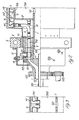
- a continuous casting plant for casting metal flat bars or sheet like elements S is shown.
- the said plant comprises two counter-rotating rollers R, rotating respectivelly in the directions of the arrows F and Fl, defining between their upper portions a pit P in which the molten metal from the tundish T is poured, and from which the said molten metal is moulded into a continuous flat bar or sheet S by the action of the said rollers R.
- the said roller comprises, as shown, a central pivot 1 formed by a tubular member of great thickness.
- a second tubular member 2 is concentrically disposed around the pivot 1, the said tubular member 2 being sealed at its ends by the annular plates 2'.
- Concentrically on the tubular member 2, the cylindrical outer mantle 4 of the roller is disposed, leaving between the inner surface of mantle 4 and the outer surface of the tubular member 2 an annular chamber 3.
- the inner surface of the mantle 4 is formed with a plurality of channels 41 for the flow of a refrigerating fluid, normally water.
- Each channel 41 is connected through a flexible pipe 6 to a flange member 7 welded to the pivot 1.
- a second flange member 11 is secured by means of bolts 10, to the flange 7.
- a plurality of cocks 12 are seated, each controlling the flow of refrigerating fluid from the inlet 19 through the passages 119 and 219 in the flanges 11 and 7, to the feeding pipes 6 and from said pipes to the refrigerating channels 41.
- the refrigerating water is fed to the inlet 19 from a suitable source, through an (undisclosed) rotating joint.
- the water flowing in the channels 41 is thereafter discharged through pipes 61, communicating with the interior of the tubular member 2, and therefrom through radial holes 101 formed in the pivot 1, into the interior of pivot 1, and therefrom through discharging pipe 20 to the exterior.
- the roller R is driven through the pinion 102 in mesh with the toothed crown 103 connected to the pivot 1.
- the roller R is supported for rotation on two end supports 9, secured to the frame (not shown) of the casting plant, with the interposition between said supports 9 and the flange 7 of an antifriction ring 8.
- a cross bar 121,122 is secured, formed at its ends with a cam like profile.
- the said cross bars 121,122 cooperates with the actuating pins 13,14, fastened to the case 15 secured to the support 9, and extending radially inwardly into the path of the said cross bars 121,122, so as to automatically open or close the cocks 12 during rotation of the roller R. In this manner it is possible to cool only that portion of the mantle 4 which is in contact with the molten metal, leaving the remaining of the mantle 4 at its average temperature.
- the thermal excursion of the mantle 4 is substantially reduced, thus reducing the thermal stress to which it is subjected.
- the chamber 3, between the channels 41 and the tubular member 2, is filled with a suitable cement 303, as it will be described in further detail below.
- the channel 41 may be formed in many ways. Some preferred embodiments of said channels are shown in Figures 6 to 8, and will be described particularly below.
- the said channels 41 are formed by securing to the inner surface of the mantle 4, for instance by means of welding, glueing or riveting, a sheet 42 provided with parallel ribs, or corrugations 142.
- the said channels 41 are formed by securing to the inner surface of the mantle 4, for instance by welding, glueing or riveting, a number of sidewise extending parallel channel-like substantially U-shaped members 43.
- the channels 41 are formed by engraving a number of grooves 44 into the inner surface of the mantle 4, and by closing said grooves by means of thin strips 45 extending between the parallel ribs 46 separating the single contiguous grooves from one another.
- the said strips may again be secured to said grooves by welding, glueing or riveting.
- they are secured by riveting the free ends of said ribs 46, as shown at 47.
- the strips 45 or the channel like elements 42 or 43 may be made of metal or of plastics.
- any suitable cement or bonding material may be used, which is apt to firmly bond the mantle 4 to the tubular member 2, or to the pivot 1.
- Suitable materials which may be used to this end are for instance semi-liquid mortars and similar materials, especially quick setting cement and/or gypsum mortars; self-hardening resins, or plastic materials which may be also mixed with sand, saw dust or other filling materials; adhesive pasts. or the like, mixed or not with inert fillers.
- anchoring elements 48,49 may be provided, as shown in Figures 2 and 7, secured both to the mantle 4 and to the tubular element 2, to be let into the filling material 303.
- the filling mass 303 has the purpose of transmitting the driving torque from the central pivot (through the tubular element 2) to the mantle 4, as well as to preserve the cylindrical shape of the mantle 4, and to sustain the thin walls of the channels 41.
- the intermediate tubular element 2 is shown between the pivot 1 and the mantle 2, the said element may be missing, and the chamber 200 defined by the said element may be filled with the filling material 303.
- roller according to the invention has many advantages with respect to the prior art rollers. Among the said advantages, the following may be cited:
- rollers according to the invention are related to the efficiency and the uniformity of its cooling.
- Rollers provided with a long mantle may present a difference in temperature of from 5° to 15°C between the cooling fluid inlet and outlet ends of the channels 41. Whenever this occours, it may be advisable to feed the channels 41 alternately from one side and from the opposite one of the roller R. In this instance; the exhaust pipes 61 are connected to the chamber 200, as shown in Figure 2. Should' the rollers be very long, and for instance should their length be in the order of 2 meters, the channels 41 are suitably fed from both ends, with their outlets 141 communicating with the central portion of the chamber 200, as shown in Figure 3.
- the length of the channel 41 is reduced to one half of the length of the mantle 4, thus reducing also the thermal difference along the channel.
Landscapes
- Engineering & Computer Science (AREA)
- Mechanical Engineering (AREA)
- Rolls And Other Rotary Bodies (AREA)
- Continuous Casting (AREA)
Applications Claiming Priority (2)
| Application Number | Priority Date | Filing Date | Title |
|---|---|---|---|
| IT8412483A IT1180469B (it) | 1984-04-06 | 1984-04-06 | Rullo raffreddato per la colata continua di prodotti piatti |
| IT1248384 | 1984-04-06 |
Publications (2)
| Publication Number | Publication Date |
|---|---|
| EP0158207A2 true EP0158207A2 (de) | 1985-10-16 |
| EP0158207A3 EP0158207A3 (de) | 1986-07-30 |
Family
ID=11140697
Family Applications (1)
| Application Number | Title | Priority Date | Filing Date |
|---|---|---|---|
| EP85103510A Ceased EP0158207A3 (de) | 1984-04-06 | 1985-03-25 | Gekühlte Rollen für das Stranggiessen von Flachplatinen |
Country Status (4)
| Country | Link |
|---|---|
| US (1) | US4669527A (de) |
| EP (1) | EP0158207A3 (de) |
| JP (1) | JPS60231556A (de) |
| IT (1) | IT1180469B (de) |
Cited By (1)
| Publication number | Priority date | Publication date | Assignee | Title |
|---|---|---|---|---|
| EP0246188A1 (de) * | 1986-05-14 | 1987-11-19 | Lauener Engineering AG | Giesswalze und Verfahren zum Ueberholen derselben |
Families Citing this family (1)
| Publication number | Priority date | Publication date | Assignee | Title |
|---|---|---|---|---|
| US5626183A (en) * | 1989-07-14 | 1997-05-06 | Fata Hunter, Inc. | System for a crown control roll casting machine |
Family Cites Families (9)
| Publication number | Priority date | Publication date | Assignee | Title |
|---|---|---|---|---|
| US2433121A (en) * | 1944-01-29 | 1947-12-23 | Beloit Iron Works | Drier drum |
| US2693012A (en) * | 1950-09-08 | 1954-11-02 | Gen Motors Corp | Method and apparatus for manufacturing sheet material |
| GB929662A (en) * | 1958-09-04 | 1963-06-26 | Paul Kleinewefers | A calender roller |
| GB890360A (en) * | 1959-11-24 | 1962-02-28 | Aluminum International Inc | Apparatus for casting molten metal |
| US3144905A (en) * | 1960-11-15 | 1964-08-18 | Albert William | Roll construction |
| US3430683A (en) * | 1967-01-12 | 1969-03-04 | American Metal Climax Inc | Feed tip for continuous strip casting machine |
| DE2149941C3 (de) * | 1971-10-06 | 1975-01-02 | Wsesojusnij Nautschno-Issledowatel' Skij I Projektno-Konstruktorskij Institut Metallurgitscheskowo Maschinostrojenija, Moskau | Kühlsystem für die Walzen einer Walzenkokille |
| JPS58168462A (ja) * | 1982-03-31 | 1983-10-04 | Hitachi Zosen Corp | 薄肉鋳片連続鋳造設備におけるツインモ−ルドロ−ラ冷却装置 |
| JPS6035221B2 (ja) * | 1982-10-12 | 1985-08-13 | 石川島播磨重工業株式会社 | 金属帯板連続鋳造方法及びその装置 |
-
1984
- 1984-04-06 IT IT8412483A patent/IT1180469B/it active
-
1985
- 1985-03-25 EP EP85103510A patent/EP0158207A3/de not_active Ceased
- 1985-03-28 US US06/716,946 patent/US4669527A/en not_active Expired - Fee Related
- 1985-04-04 JP JP60070156A patent/JPS60231556A/ja active Pending
Cited By (2)
| Publication number | Priority date | Publication date | Assignee | Title |
|---|---|---|---|---|
| EP0246188A1 (de) * | 1986-05-14 | 1987-11-19 | Lauener Engineering AG | Giesswalze und Verfahren zum Ueberholen derselben |
| US4773468A (en) * | 1986-05-14 | 1988-09-27 | Larex Ag | Casting roll |
Also Published As
| Publication number | Publication date |
|---|---|
| JPS60231556A (ja) | 1985-11-18 |
| IT8412483A0 (it) | 1984-04-06 |
| EP0158207A3 (de) | 1986-07-30 |
| IT1180469B (it) | 1987-09-23 |
| US4669527A (en) | 1987-06-02 |
Similar Documents
| Publication | Publication Date | Title |
|---|---|---|
| US7422049B2 (en) | Tubular mould for continuous casting | |
| EP1106321B1 (de) | Rotierende Kühlwalze | |
| US3452394A (en) | Extruder heads | |
| WO1998017459A1 (en) | Modular disk coextrusion die | |
| US7654726B2 (en) | Multi-shaft extruder | |
| GB2156252A (en) | Improvements in continuous casting | |
| US20130122133A1 (en) | Continuous Bi-Metallic Twin Bore Barrel for Screw Extruder and Method of Making Same | |
| EP0029416A1 (de) | Kühlelement für Lichtbogenschmelzöfen | |
| EP0158207A2 (de) | Gekühlte Rollen für das Stranggiessen von Flachplatinen | |
| CN86107495A (zh) | 中空带底铸造产品的铸型和铸造方法 | |
| NZ270931A (en) | Pressbending apparatus for glass sheets such as vehicle windscreens | |
| US3295172A (en) | Continuous casting mold | |
| CZ236589A3 (en) | Apparatus for continuous or semi-continuous casting of metallic materials | |
| BG64511B1 (bg) | Метод за производство на съставен охладителен елемент за топилна зона на металургичен реактор и охладителен елемент, произведен по метода | |
| US7147033B2 (en) | Dual drum type continuous casting device and method for continuous casting | |
| CN106578272A (zh) | 一种巧克力浇注装置 | |
| US1969135A (en) | Heat exchanger | |
| CN212598769U (zh) | 一种用于铸管生产的新型流槽 | |
| RU2161546C1 (ru) | Способ непрерывного многоручьевого горизонтального литья плоских слитков, установка для осуществления способа, многоручьевой кристаллизатор и тянущее устройство для этой установки | |
| JPS6213996A (ja) | パネル型熱交換器 | |
| KR102096757B1 (ko) | 원심주조 금형 조립체 | |
| CN207592739U (zh) | 一种制备高铬铸铁基陶瓷增强复合材料的装置 | |
| JPS61209753A (ja) | モ−ルド板 | |
| GB1564738A (en) | Tuyeres | |
| JPS6213995A (ja) | パネル型熱交換器 |
Legal Events
| Date | Code | Title | Description |
|---|---|---|---|
| PUAI | Public reference made under article 153(3) epc to a published international application that has entered the european phase |
Free format text: ORIGINAL CODE: 0009012 |
|
| AK | Designated contracting states |
Designated state(s): AT BE CH DE FR GB IT LI LU NL SE |
|
| PUAL | Search report despatched |
Free format text: ORIGINAL CODE: 0009013 |
|
| AK | Designated contracting states |
Kind code of ref document: A3 Designated state(s): AT BE CH DE FR GB IT LI LU NL SE |
|
| 17P | Request for examination filed |
Effective date: 19861105 |
|
| 17Q | First examination report despatched |
Effective date: 19870409 |
|
| STAA | Information on the status of an ep patent application or granted ep patent |
Free format text: STATUS: THE APPLICATION HAS BEEN REFUSED |
|
| 18R | Application refused |
Effective date: 19881010 |