EP0158241B1 - Interrupteur électrique - Google Patents
Interrupteur électrique Download PDFInfo
- Publication number
- EP0158241B1 EP0158241B1 EP85103775A EP85103775A EP0158241B1 EP 0158241 B1 EP0158241 B1 EP 0158241B1 EP 85103775 A EP85103775 A EP 85103775A EP 85103775 A EP85103775 A EP 85103775A EP 0158241 B1 EP0158241 B1 EP 0158241B1
- Authority
- EP
- European Patent Office
- Prior art keywords
- lever
- contact
- point
- arm
- armature
- Prior art date
- Legal status (The legal status is an assumption and is not a legal conclusion. Google has not performed a legal analysis and makes no representation as to the accuracy of the status listed.)
- Expired - Lifetime
Links
- 230000008878 coupling Effects 0.000 claims description 2
- 238000010168 coupling process Methods 0.000 claims description 2
- 238000005859 coupling reaction Methods 0.000 claims description 2
- 238000010791 quenching Methods 0.000 claims description 2
- 230000000171 quenching effect Effects 0.000 claims 1
- 239000004020 conductor Substances 0.000 description 2
- 238000010276 construction Methods 0.000 description 2
- 230000007246 mechanism Effects 0.000 description 2
- 238000000926 separation method Methods 0.000 description 2
- 230000009471 action Effects 0.000 description 1
- 238000009434 installation Methods 0.000 description 1
- 239000002184 metal Substances 0.000 description 1
- 230000007935 neutral effect Effects 0.000 description 1
- 230000004044 response Effects 0.000 description 1
- 230000001960 triggered effect Effects 0.000 description 1
Images
Classifications
-
- H—ELECTRICITY
- H01—ELECTRIC ELEMENTS
- H01H—ELECTRIC SWITCHES; RELAYS; SELECTORS; EMERGENCY PROTECTIVE DEVICES
- H01H71/00—Details of the protective switches or relays covered by groups H01H73/00 - H01H83/00
- H01H71/10—Operating or release mechanisms
- H01H71/12—Automatic release mechanisms with or without manual release
- H01H71/24—Electromagnetic mechanisms
- H01H71/2409—Electromagnetic mechanisms combined with an electromagnetic current limiting mechanism
-
- H—ELECTRICITY
- H01—ELECTRIC ELEMENTS
- H01H—ELECTRIC SWITCHES; RELAYS; SELECTORS; EMERGENCY PROTECTIVE DEVICES
- H01H71/00—Details of the protective switches or relays covered by groups H01H73/00 - H01H83/00
- H01H71/10—Operating or release mechanisms
- H01H71/12—Automatic release mechanisms with or without manual release
- H01H71/24—Electromagnetic mechanisms
- H01H71/2472—Electromagnetic mechanisms with rotatable armatures
Definitions
- the invention relates to a single-pole electrical switch with a fixed contact point and a movable contact piece formed on a contact lever, with an arc extinguishing device assigned to the contact point, with an electromagnetic and / or thermal release and with a rotary lever having a latching point, the magnet armature of the electromagnetic release to open the contact point acts on the latching point
- Electrical circuit breakers whose magnetic release is a so-called folding armature release, have the problem of deflecting the rotary movement of the armature onto the rotary movement of the movable contact lever, in particular with regard to the task of quickly opening the contact point in order to achieve a current limitation.
- the quick opening of the con Tact point causes the hinged armature to act on a push rod which is movably guided parallel to the central axis of the magnetic core, which strikes the contact lever when the hinged armature is tightening.
- This design is complex, since the push rod guide must be designed very precisely.
- a switch of the type mentioned is known from DE-C 21 32 738.
- the anchor designed as an impact anchor, acts on a first double-arm lever, which pivots a rotary lever, which forms a latching point with another lever, to open the latching point; when the latching point is opened, a switching mechanism with a toggle lever arrangement is released so that the contact lever can move in the opening direction.
- a further double arm lever is provided, which strikes the contact lever when the impact anchor is tightened and opens it.
- the path from the impact anchor to the contact point to its opening is a fairly long way, since the switching mechanism is interposed, so that the second lever is required in order to achieve a quick contact separation.
- the object of the invention is to achieve a quick contact separation with a simplified construction of the switching device.
- This object is achieved in that on one arm of the rotary lever designed as a double arm in the range of motion of the magnetic armature designed as a hinged armature for coupling the hinged armature with the rotary lever in the switch-off direction nose is formed, and that the other arm forms the latching point with the contact lever and when switching off it hits the contalet lever carrying the movable contact piece to open the contalet point.
- the switching device according to DE-A 22 42 128 does not have a hinged anchor, but an impact anchor, and the impact anchor also strikes the arm which is used directly to actuate the contact lever.
- an electrical switch has become known which has two contact points which are coupled to one another at least for manual switching off, one contact point of a phase conductor and the other Contact point are assigned to a neutral conductor.
- a switch with two contact points is to be created, which can be converted by simple measures so that either one contact point or both contact points can each be assigned an arc-quenching plate package.
- the housing is divided into two parts, and the contact pieces are also coupled to one another in a suitable form.
- a further embodiment of the invention is characterized in that the rotary lever strikes the contact lever approximately in the middle of the contact lever, approximately in the direction of the opening movement and approximately perpendicular to the longitudinal and transverse extension.
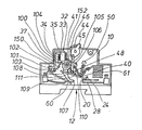
- the sole figure shows an insight into a switch according to the invention.
- the switch has a housing 10 which is designed in a shell construction and has two housing shells (not shown further).
- the housing has a recess 12 in its lower area, which enables the switching device to be snapped onto a U-shaped support rail in an installation distribution.
- the switching device has a contact point 20 which is formed from a movable contact piece 24 and a fixed contact piece 28.
- a hinged armature system 32 with a yoke 33, a coil 34 and a magnetic core 35 is provided.
- the magnetic core works together with a hinged armature 104, one end of which is supported at 37 on the leg 100 of the yoke 33 running parallel to the magnetic core 35.
- the switch has a contact lever 40, on which the movable contact piece 24 is integrally formed.
- a shift lever 45 is mounted on an axis 44, on which a rod 46 is articulated eccentrically to the axis 44 and is connected to the contact lever 40 via an eyelet 110 on the axis 48 passing through the contact lever 40.
- a tension spring 50 acts on the contact lever 40 and acts on the contact lever in the direction of opening.
- the yoke 33 essentially has an approximately Z-shaped shape, with a leg 101 adjoining the leg 100 of the yoke, which runs parallel to the central axis of the magnetic core 35, in an L-shaped manner, in which one Adjusting screw 102 is screwed in.
- a nut in the region of the leg 101, into which the adjusting screw is screwed through the leg 101.
- the nut would be loose in relation to the yoke, but fixed in the housing so that the adjusting screw does not turn the nut when screwing in.
- the vertical, extending leg 100 extends into a holding bracket 103, the other free leg of which is used to hold a thermobimetal 60.
- the tip of the adjusting screw 102 presses on the inner surface of this leg with the bimetallic 60, whereby the tripping can be set in the event of an overcurrent.
- a hinged armature 104 is mounted, which cooperates with a ratchet lever 105 designed as a rotary lever.
- the hinged anchor 104 acts directly on a nose 106 Pawl lever 105, which is rotatably mounted at 41.
- An extension 107 which projects into the movement path of the movable contact lever 40, is also formed on the latch lever 105.
- a rotation of the armature 104 also causes the movable contact lever 40 to rotate in the same direction via the nose 106 and the extension 107.
- a latching point 108 is provided diametrically opposite the nose 106, against which the contact lever 40 is pressed by means of the articulated gear, which is formed from the shift lever 45, the rod 46 and the support 48.
- a leaf spring 109 is guided on the movable contact lever, against which the axis 48 presses from above, so that the holder or the connection between the rod 46 and the contact lever 40 is a resilient connection.
- the spring 109 is significantly stronger than the spring 50, since it has to exert both the force of the spring 50, the contact force and the latching force.
- the eyelet 110 forms a kind of elongated hole 111 with the contact lever 40 and the axis 48 is pressed by the spring 109 against the upper end, that is to say the end of the elongated hole 111, which lies opposite the contact lever.
- the bimetallic metal 60 acts on the pawl lever 105 and, in the event of an overcurrent, rotates it counterclockwise about the axis 41. This releases the latching point 108 and the movable contact lever 40 can be moved into the switched-off position under the tension of the spring 50.
- the latch In the event of a release, the latch is only activated place solved and after overcoming the lead due to the distance between extension 107 and contact lever, the extension 107 acts on the contact lever.
- the hinged armature is constantly under the action of a tension spring 150, which continuously acts on the hinged armature in the switch-off direction and also determines the magnetic response value.
- a spiral spring 152 is provided which continuously acts on the latch lever in a clockwise direction, ie continuously presses the nose 108 against the contact lever 40 and thus ensures the latching.
Landscapes
- Physics & Mathematics (AREA)
- Electromagnetism (AREA)
- Breakers (AREA)
- Switch Cases, Indication, And Locking (AREA)
Claims (2)
- Coupe-circuit électrique unipolaire, comprenant un contact (20) présentant une pièce de contact (28) fixe et une pièce de contact (24) mobile, formée d'une seule pièce sur un levier de contact (40), un dispositif (61) d'extinction d'arc électrique associé au contact (20), un déclencheur électromagnétique (35) et/ou thermique (60), et un levier rotatif (105) présentant un emplacement d'encliquetage (108), l'armature (104) du déclencheur électromagnétique (35) agissant sur l'emplacement d'encliquetage (108) pour l'ouverture du contact (20), caractérisé par le fait que sur un bras du levier rotatif (105) réalisé sous forme de levier à deux bras, il est formé d'une seule pièce un doigt (106) faisant saillie dans la zone de mouvement de l'armature (104), réalisée sous forme d'armature battante, pour le couplage de l'armature battante avec le levier rotatif (105) dans la direction de la coupure, et que l'autre bras forme, avec le levier de contact (40), l'emplacement d'encliquetage (108) et tombe, lors de la coupure, sur le levier de contact (40) portant la pièce de contact (24) mobile, en vue de l'ouverture du contact (20).
- Coupe-circuit selon la revendication 1, caractérisé par le fait que le levier rotatif (105) tombe à peu près au milieu du levier de contact (40) à peu près dans la direction du mouvement d'ouverture et à peu près perpendiculairement à la longueur et la largeur du levier de contact (40).
Applications Claiming Priority (2)
| Application Number | Priority Date | Filing Date | Title |
|---|---|---|---|
| DE19843413808 DE3413808A1 (de) | 1984-04-12 | 1984-04-12 | Elektrischer schalter |
| DE3413808 | 1984-04-12 |
Publications (3)
| Publication Number | Publication Date |
|---|---|
| EP0158241A2 EP0158241A2 (fr) | 1985-10-16 |
| EP0158241A3 EP0158241A3 (en) | 1988-04-06 |
| EP0158241B1 true EP0158241B1 (fr) | 1991-02-27 |
Family
ID=6233391
Family Applications (1)
| Application Number | Title | Priority Date | Filing Date |
|---|---|---|---|
| EP85103775A Expired - Lifetime EP0158241B1 (fr) | 1984-04-12 | 1985-03-28 | Interrupteur électrique |
Country Status (7)
| Country | Link |
|---|---|
| EP (1) | EP0158241B1 (fr) |
| AU (1) | AU4098885A (fr) |
| DE (2) | DE3413808A1 (fr) |
| GB (1) | GB2157499B (fr) |
| IN (1) | IN164944B (fr) |
| NZ (1) | NZ211781A (fr) |
| SG (1) | SG5389G (fr) |
Families Citing this family (2)
| Publication number | Priority date | Publication date | Assignee | Title |
|---|---|---|---|---|
| AT408929B (de) * | 1995-07-28 | 2002-04-25 | Felten & Guilleaume Ag Oester | Einpoliger ausschalter |
| IT1306913B1 (it) * | 1998-12-15 | 2001-10-11 | Gewiss Spa | Interruttore elettrico magnetotermico da incasso |
Family Cites Families (8)
| Publication number | Priority date | Publication date | Assignee | Title |
|---|---|---|---|---|
| DE744559C (de) * | 1940-08-15 | 1944-01-20 | Wilhelm Leyhausen | Kleinselbstschalter |
| GB702790A (en) * | 1951-08-29 | 1954-01-20 | English Electric Co Ltd | Improvements in and relating to electro-magnetic relays |
| DE2124353A1 (de) * | 1971-05-17 | 1972-11-30 | Geyer Fa Christian | Mechanismus für Selbstschalter |
| DE2132738B1 (de) * | 1971-07-01 | 1972-07-06 | Ellenberger & Poensgen | Ein- oder mehrpoliger UEberstromschalter mit thermischer und/oder elektromagnetischer Ausloesung |
| DE2138381C3 (de) * | 1971-07-31 | 1975-05-15 | Siemens Ag, 1000 Berlin Und 8000 Muenchen | Schutzschalter, insbesondere Leitungsschutzschalter |
| DE2242128A1 (de) * | 1972-08-26 | 1974-03-07 | Geyer Fa Christian | Mechanismus fuer selbstschalter |
| DE2614461C2 (de) * | 1976-04-03 | 1978-02-23 | Brown, Boveri & Cie Ag, 6800 Mannheim | Leitungsschutzschalter mit elektromagnetischem Auslöser |
| DE3242062A1 (de) * | 1982-11-13 | 1984-05-17 | Brown, Boveri & Cie Ag, 6800 Mannheim | Elektrischer schalter |
-
1984
- 1984-04-12 DE DE19843413808 patent/DE3413808A1/de not_active Withdrawn
-
1985
- 1985-03-28 DE DE8585103775T patent/DE3581821D1/de not_active Expired - Lifetime
- 1985-03-28 EP EP85103775A patent/EP0158241B1/fr not_active Expired - Lifetime
- 1985-04-10 AU AU40988/85A patent/AU4098885A/en not_active Abandoned
- 1985-04-12 NZ NZ211781A patent/NZ211781A/en unknown
- 1985-04-12 GB GB08509401A patent/GB2157499B/en not_active Expired
- 1985-08-23 IN IN612/CAL/85A patent/IN164944B/en unknown
-
1989
- 1989-01-30 SG SG53/89A patent/SG5389G/en unknown
Also Published As
| Publication number | Publication date |
|---|---|
| GB8509401D0 (en) | 1985-05-15 |
| GB2157499A (en) | 1985-10-23 |
| SG5389G (en) | 1989-09-22 |
| IN164944B (fr) | 1989-07-15 |
| EP0158241A3 (en) | 1988-04-06 |
| EP0158241A2 (fr) | 1985-10-16 |
| DE3413808A1 (de) | 1985-10-17 |
| AU4098885A (en) | 1985-10-17 |
| NZ211781A (en) | 1988-03-30 |
| GB2157499B (en) | 1988-10-19 |
| DE3581821D1 (de) | 1991-04-04 |
Similar Documents
| Publication | Publication Date | Title |
|---|---|---|
| EP0174904B1 (fr) | Dispositif de contact pour disjoncteur basse tension avec un levier de contact à deux bras | |
| DE3242062C2 (fr) | ||
| DE3323474C2 (de) | Stromkreisunterbrecher | |
| EP0144799A2 (fr) | Disjoncteur | |
| EP0391086B1 (fr) | Dispositeur de protection à courant excessif commandé par un bouton-poussoir | |
| EP0159960B1 (fr) | Appareil interrupteur sous vide avec un dispositif d'entraînement ainsi qu'un ressort qui s'appuie sur le plot de contact mobile du tube interrupteur | |
| EP0130560A2 (fr) | Interrupteur limiteur de courant | |
| EP1728260B1 (fr) | Mecanisme de commutation pour appareil de distribution d'installation electrique | |
| EP0243648B1 (fr) | Disjoncteur électrique | |
| EP0028389B1 (fr) | Disjoncteur de protection à basse tension | |
| DE69516790T2 (de) | Mittelspannungsschalter oder Schutzschalter | |
| EP0279363A2 (fr) | Disjoncteur de protection pour courant de défaut | |
| EP0592007B1 (fr) | Dispositif de commutation | |
| DE3734396A1 (de) | Elektrisches schaltgeraet | |
| EP0158241A2 (fr) | Interrupteur électrique | |
| EP0591905B1 (fr) | Commutateur électrique | |
| DE1588146A1 (de) | Druckknopfbetaetigter UEberstromschalter | |
| DE69833637T2 (de) | Selektiver Auslöser für Leistungsschalter | |
| CH579823A5 (en) | Manually operated protective switch - is for thermal and or magnetic automatic release and has swivel toggle levers | |
| DE3808012C2 (fr) | ||
| AT404647B (de) | Elektrischer schutzschalter | |
| EP0041049A2 (fr) | Disjoncteur de protection | |
| DE102005046640B4 (de) | Elektrisches Installationsgerät | |
| DE2717444A1 (de) | Mehrpoliges thermisches ueberstromrelais | |
| EP1071108B1 (fr) | Actionneur électromagnétique, en particulier un dispositif de déclenchement, en particulier pour un disjoncteur |
Legal Events
| Date | Code | Title | Description |
|---|---|---|---|
| PUAI | Public reference made under article 153(3) epc to a published international application that has entered the european phase |
Free format text: ORIGINAL CODE: 0009012 |
|
| AK | Designated contracting states |
Designated state(s): BE DE FR IT |
|
| PUAL | Search report despatched |
Free format text: ORIGINAL CODE: 0009013 |
|
| AK | Designated contracting states |
Kind code of ref document: A3 Designated state(s): BE DE FR IT |
|
| 17P | Request for examination filed |
Effective date: 19880513 |
|
| RAP1 | Party data changed (applicant data changed or rights of an application transferred) |
Owner name: ASEA BROWN BOVERI AKTIENGESELLSCHAFT |
|
| 17Q | First examination report despatched |
Effective date: 19900116 |
|
| GRAA | (expected) grant |
Free format text: ORIGINAL CODE: 0009210 |
|
| ITF | It: translation for a ep patent filed | ||
| AK | Designated contracting states |
Kind code of ref document: B1 Designated state(s): BE DE FR IT |
|
| ET | Fr: translation filed | ||
| REF | Corresponds to: |
Ref document number: 3581821 Country of ref document: DE Date of ref document: 19910404 |
|
| PLBE | No opposition filed within time limit |
Free format text: ORIGINAL CODE: 0009261 |
|
| STAA | Information on the status of an ep patent application or granted ep patent |
Free format text: STATUS: NO OPPOSITION FILED WITHIN TIME LIMIT |
|
| 26N | No opposition filed | ||
| PGFP | Annual fee paid to national office [announced via postgrant information from national office to epo] |
Ref country code: FR Payment date: 19930216 Year of fee payment: 9 |
|
| PG25 | Lapsed in a contracting state [announced via postgrant information from national office to epo] |
Ref country code: FR Effective date: 19941130 |
|
| REG | Reference to a national code |
Ref country code: FR Ref legal event code: ST |
|
| PGFP | Annual fee paid to national office [announced via postgrant information from national office to epo] |
Ref country code: BE Payment date: 19980212 Year of fee payment: 14 |
|
| PG25 | Lapsed in a contracting state [announced via postgrant information from national office to epo] |
Ref country code: BE Free format text: LAPSE BECAUSE OF NON-PAYMENT OF DUE FEES Effective date: 19990331 |
|
| BERE | Be: lapsed |
Owner name: ASEA BROWN BOVERI A.G. Effective date: 19990331 |
|
| PGFP | Annual fee paid to national office [announced via postgrant information from national office to epo] |
Ref country code: DE Payment date: 20011129 Year of fee payment: 18 |
|
| PG25 | Lapsed in a contracting state [announced via postgrant information from national office to epo] |
Ref country code: DE Free format text: LAPSE BECAUSE OF NON-PAYMENT OF DUE FEES Effective date: 20031001 |