EP0158251B2 - Circuit de fonctionnement en standby d'un récepteur de télévision - Google Patents
Circuit de fonctionnement en standby d'un récepteur de télévision Download PDFInfo
- Publication number
- EP0158251B2 EP0158251B2 EP85103860A EP85103860A EP0158251B2 EP 0158251 B2 EP0158251 B2 EP 0158251B2 EP 85103860 A EP85103860 A EP 85103860A EP 85103860 A EP85103860 A EP 85103860A EP 0158251 B2 EP0158251 B2 EP 0158251B2
- Authority
- EP
- European Patent Office
- Prior art keywords
- remote control
- pulses
- control signal
- signal amplifier
- switch
- Prior art date
- Legal status (The legal status is an assumption and is not a legal conclusion. Google has not performed a legal analysis and makes no representation as to the accuracy of the status listed.)
- Expired - Lifetime
Links
- 238000011156 evaluation Methods 0.000 claims abstract description 25
- 238000000034 method Methods 0.000 claims abstract 3
- 239000000243 solution Substances 0.000 description 10
- 230000003750 conditioning effect Effects 0.000 description 3
- 238000000926 separation method Methods 0.000 description 2
- 230000006641 stabilisation Effects 0.000 description 2
- 238000011105 stabilization Methods 0.000 description 2
- 230000000712 assembly Effects 0.000 description 1
- 238000000429 assembly Methods 0.000 description 1
- 230000003139 buffering effect Effects 0.000 description 1
- 239000003990 capacitor Substances 0.000 description 1
- 230000001143 conditioned effect Effects 0.000 description 1
- 238000001514 detection method Methods 0.000 description 1
- 238000012423 maintenance Methods 0.000 description 1
- 230000006386 memory function Effects 0.000 description 1
Images
Classifications
-
- H—ELECTRICITY
- H04—ELECTRIC COMMUNICATION TECHNIQUE
- H04N—PICTORIAL COMMUNICATION, e.g. TELEVISION
- H04N5/00—Details of television systems
- H04N5/63—Generation or supply of power specially adapted for television receivers
-
- H—ELECTRICITY
- H02—GENERATION; CONVERSION OR DISTRIBUTION OF ELECTRIC POWER
- H02M—APPARATUS FOR CONVERSION BETWEEN AC AND AC, BETWEEN AC AND DC, OR BETWEEN DC AND DC, AND FOR USE WITH MAINS OR SIMILAR POWER SUPPLY SYSTEMS; CONVERSION OF DC OR AC INPUT POWER INTO SURGE OUTPUT POWER; CONTROL OR REGULATION THEREOF
- H02M1/00—Details of apparatus for conversion
- H02M1/0003—Details of control, feedback or regulation circuits
- H02M1/0032—Control circuits allowing low power mode operation, e.g. in standby mode
-
- Y—GENERAL TAGGING OF NEW TECHNOLOGICAL DEVELOPMENTS; GENERAL TAGGING OF CROSS-SECTIONAL TECHNOLOGIES SPANNING OVER SEVERAL SECTIONS OF THE IPC; TECHNICAL SUBJECTS COVERED BY FORMER USPC CROSS-REFERENCE ART COLLECTIONS [XRACs] AND DIGESTS
- Y02—TECHNOLOGIES OR APPLICATIONS FOR MITIGATION OR ADAPTATION AGAINST CLIMATE CHANGE
- Y02B—CLIMATE CHANGE MITIGATION TECHNOLOGIES RELATED TO BUILDINGS, e.g. HOUSING, HOUSE APPLIANCES OR RELATED END-USER APPLICATIONS
- Y02B70/00—Technologies for an efficient end-user side electric power management and consumption
- Y02B70/10—Technologies improving the efficiency by using switched-mode power supplies [SMPS], i.e. efficient power electronics conversion e.g. power factor correction or reduction of losses in power supplies or efficient standby modes
Definitions
- the invention relates to a circuit arrangement according to the preamble of the first claim.
- DE-A1-31 37 081 describes a television receiver with IR remote control, which is completely separated from the network in stand-by mode.
- the stand-by power supply takes place by means of solar cells.
- the design provides for buffering the solar cells with rechargeable batteries.
- C-MOS preamplifiers and receive decoder circuits it is possible to reduce the power consumption at approx. 5 V to values in the order of 1 mA.
- DE-A1-32 42 333 became known, according to which a ready-to-receive circuit for remote-controlled television receivers, in which the remote control receiver 2 accommodated in the television set 1 is connected to the network via a stand-by transformer 6 and a voltage stabilization 10 and at which a switching relay 11 is provided for the mains connection of the television set 1.
- the usual user-operated mains switch with wiping contact for setting the switching relay 11 is to be omitted.
- the task does not include the requirement for a particularly low-performance stand-by operation, which is therefore not possible with the task solution.
- the stand-by transformer 6 is permanently connected to the network, between which and the voltage stabilization 10 a low-voltage standby switch 9 is provided, and the relay is set by a transistor 16, which is connected in series with a capacitor 13 and resistor 14 receives differentiated switching pulses between the stand-by supply line 20 and ground. From the description of Fig. 1 it is clear that the remote control receiver 2, which contains the command decoder 3 and the network flip-flop and necessarily an amplifier and preamplifier for the remote control signal, not mentioned, is constantly fed during stand-by operation .
- the object of the present invention was to develop circuit arrangements which enable a considerably reduced power consumption in stand-by mode and do not require any significant costs for the circuitry.
- the remote control signal amplifier is fed during this operation.
- the remote control When the remote control is operated, it emits correspondingly coded pulses.
- these are fed to a signal conditioning circuit and an evaluation circuit, the latter being only supplied with voltage and put into operation when the conditioned signal switches an electronic switch on. If the evaluation circuit recognizes the signal as a switch-on signal, it outputs a switch-on signal to the power supply unit of the television set and itself ensures that its power supply is maintained via the electronic switch. However, if the evaluation circuit determines that the received pulses do not correspond to the agreed code, the connection of the electronic switch is not maintained.
- the remote control signal amplifier from the network is constantly supplied with a rectified voltage during stand-by operation and works with an optocoupler and a switching power supply that can take three switching stages. It remains switched off during stand-by operation (stand-by I). If the remote control signal amplifier receives signals from the encoder, it sends pulses to the switching power supply, which switches it to a standby II switching stage. At the same time, the same impulses reach the evaluation circuit via the optocoupler, which is required here for network separation. This detects switch-on pulses and switches the switching power supply to its third switching stage, normal operation, whereby the television receiver and the evaluation circuit are supplied with voltage. If there are no switch-on impulses or no further impulses for recognition are received from the remote control signal amplifier, the stand-by-II function of the switching power supply is canceled again, i.e. it is switched back to its first standby I switching stage.
- a local control part on the television receiver if provided, must cooperate with the evaluation circuit so that the television receiver can be switched on directly.
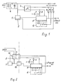
- a remote control signal amplifier 1 shows a circuit arrangement in which a remote control signal amplifier 1 is fed from a power supply unit 4 in standby mode while all other consumers are still switched off.
- the remote control signal amplifier 1 receives signals from an encoder (not shown), it emits pulses to a connected evaluation circuit 5 and to a signal conditioning circuit 2 which switches the electronic switch 3 through the diode 11.
- the evaluation circuit 5 is supplied with voltage and checks the incoming pulses. If there are switch-on pulses according to the coding, it maintains its voltage supply itself via the diode 9. In the other case, if no further pulses come from the remote control signal amplifier 1, the switch 3 is switched off again by the signal conditioning circuit 2, as a result of which the circuit remains in stand-by mode.
- the evaluation circuit 5 issues the switch-on command at its output by means of an L signal to the power pack or switching power pack of the television receiver.
- the electronic switch 3 can also be activated from the local control unit 6 and the device can thus be switched on.
- the evaluation circuit 5 recognizes that the local control unit 6 has switched on via the diode 10 and also coffins for the maintenance of the power supply via the electronic switch 3. The energy required for this short period of time is supplied by the electrolytic power pack 4.
- an evaluation circuit 5 with preferred storage of the last set values is indicated by the fact that a battery 7 and a diode 8 are connected in such a way that the battery 7 supplies the minimum voltage required for the memory function during stand-by operation .
- this voltage is increased to its operating value via the electronic switch 3 and the evaluation circuit 5 is activated.
- a connection to the power supply of the television receiver is connected via a diode. This is intended to indicate that current is fed in via this connection as soon as a switch-on signal has resulted in the television receiver being switched on.
- FIG. 2 shows a second example with mains separation at the input (dash-dotted line) in that a switching power supply 12 with three switching stages is provided.
- a switching power supply 12 with three switching stages is provided.
- stand-by-I mode first switching stage
- only the part of the switching power supply 12 indicated by the dashed line is used to feed the remote control signal amplifier 1 with a voltage derived from the 220 V mains connection.
- the remote control signal amplifier 1 receives pulses from the transmitter, it outputs pulses to the switching power supply, which brings it into the second switching stage, stand-by II operation, and at the same time these pulses reach the evaluation circuit via an intermediate opto-coupler 13 5, mostly a microprocessor, which now receives its required energy from the switching power supply 12.
- the switching power supply 12 is switched to its third switching stage, normal operation, and thus the television set is fed. However, if no detection takes place and no further pulses arrive, the switching power supply 12 falls back into its first switching stage, only stand-by supply for the remote control amplifier (stand-by-I). The switching power supply 12 and thus the television set can also be switched on directly by the local control unit 6.
- the switching power supply 12 goes into the second switching stage only while the remote control is being operated. As in the first example described, this is associated with greater operational reliability.
Landscapes
- Engineering & Computer Science (AREA)
- Multimedia (AREA)
- Signal Processing (AREA)
- Selective Calling Equipment (AREA)
- Details Of Television Systems (AREA)
- Television Receiver Circuits (AREA)
- Testing, Inspecting, Measuring Of Stereoscopic Televisions And Televisions (AREA)
- Remote Monitoring And Control Of Power-Distribution Networks (AREA)
- Two-Way Televisions, Distribution Of Moving Picture Or The Like (AREA)
- Circuits Of Receivers In General (AREA)
Claims (2)
Priority Applications (1)
| Application Number | Priority Date | Filing Date | Title |
|---|---|---|---|
| AT85103860T ATE39205T1 (de) | 1984-04-03 | 1985-03-30 | Schaltungsanordnung fuer den stand-by-betrieb eines fernsehempfaengers. |
Applications Claiming Priority (2)
| Application Number | Priority Date | Filing Date | Title |
|---|---|---|---|
| DE3412341A DE3412341C1 (de) | 1984-04-03 | 1984-04-03 | Schaltungskonzept fuer den stand-by-Betrieb eines Fernsehempfaengers |
| DE3412341 | 1984-04-03 |
Publications (3)
| Publication Number | Publication Date |
|---|---|
| EP0158251A1 EP0158251A1 (fr) | 1985-10-16 |
| EP0158251B1 EP0158251B1 (fr) | 1988-12-07 |
| EP0158251B2 true EP0158251B2 (fr) | 1993-02-24 |
Family
ID=6232442
Family Applications (1)
| Application Number | Title | Priority Date | Filing Date |
|---|---|---|---|
| EP85103860A Expired - Lifetime EP0158251B2 (fr) | 1984-04-03 | 1985-03-30 | Circuit de fonctionnement en standby d'un récepteur de télévision |
Country Status (3)
| Country | Link |
|---|---|
| EP (1) | EP0158251B2 (fr) |
| AT (1) | ATE39205T1 (fr) |
| DE (2) | DE3412341C1 (fr) |
Families Citing this family (8)
| Publication number | Priority date | Publication date | Assignee | Title |
|---|---|---|---|---|
| DE3808863A1 (de) * | 1988-03-17 | 1989-09-28 | Philips Patentverwaltung | Stromversorgungsanordnung |
| DE4240351C1 (en) * | 1992-11-06 | 1993-09-23 | Rft Rundfunk-Fernseh-Telekommunikation Ag, 39418 Stassfurt, De | Standby circuit for remotely controlled video equipment - incorporates switched-capacitor feed to mains rectifier providing reduced output while load-switching relay is not energised. |
| EP0610700B1 (fr) * | 1993-01-30 | 1998-12-23 | Deutsche Thomson-Brandt Gmbh | Circuit d'alimentation pour appareil électronique de consommation |
| DE4321948C3 (de) * | 1993-07-01 | 1999-02-25 | Siemens Ag | Standby-Schaltung für elektrische Verbraucher |
| AT402461B (de) * | 1994-01-13 | 1997-05-26 | Koch Walter | Fernsteuerung für ein netzgespeistes elektrogerät |
| DE19652604A1 (de) * | 1996-04-23 | 1997-10-30 | Thomson Brandt Gmbh | Netzteil für ein Gerät mit Standby-Betrieb |
| WO2000036830A1 (fr) * | 1998-12-11 | 2000-06-22 | Siemens Ag Österreich | Circuit de reserve :d'attente sans courant destine a des appareils dotes d'une telecommande optique |
| KR100376131B1 (ko) * | 2000-09-22 | 2003-03-15 | 삼성전자주식회사 | 대기전원 절전형 전원장치 및 그 제어방법 |
Family Cites Families (9)
| Publication number | Priority date | Publication date | Assignee | Title |
|---|---|---|---|---|
| US3603732A (en) | 1969-06-05 | 1971-09-07 | Rca Corp | Instant-on circuitry for solid state television receivers |
| JPS50103091U (fr) * | 1974-01-29 | 1975-08-25 | ||
| DE2458302C3 (de) | 1974-12-10 | 1981-06-04 | Blaupunkt-Werke Gmbh, 3200 Hildesheim | Sperrwandler-Netzteil für einen Fernsehempfänger mit Ultraschall-Fernbedienung |
| DE2620191C2 (de) * | 1976-05-07 | 1982-05-06 | Graetz Gmbh & Co Ohg, 5990 Altena | Schaltnetzteil für die Versorgung eines Fernsehgerätes |
| DE3045715C2 (de) * | 1980-12-04 | 1986-01-16 | Loewe Opta Gmbh, 8640 Kronach | Fernsteuerbares nachrichtentechnisches Gerät |
| DE3137081A1 (de) * | 1981-09-17 | 1983-03-24 | Siemens AG, 1000 Berlin und 8000 München | Fernseh-empfaenger mit infrarot-fernbedienung |
| DE3206009A1 (de) * | 1982-02-19 | 1983-09-08 | Loewe Opta Gmbh, 8640 Kronach | Schaltungsanordnung zum ein- und ausschalten eines fernsteuerbaren fernsehempfangsgeraetes |
| DE3223756C2 (de) * | 1982-06-25 | 1984-08-23 | Licentia Patent-Verwaltungs-Gmbh, 6000 Frankfurt | Schaltnetzteil für ein elektrisches Gerät mit Bereitschaftsbetrieb, insbesondere einen Fernsehempfänger |
| DE3242333A1 (de) * | 1982-11-16 | 1984-05-17 | Blaupunkt-Werke Gmbh, 3200 Hildesheim | Empfangsbereitschafts-schaltung fuer fernsehempfaenger mit fernbedienung |
-
1984
- 1984-04-03 DE DE3412341A patent/DE3412341C1/de not_active Expired - Lifetime
-
1985
- 1985-03-30 AT AT85103860T patent/ATE39205T1/de not_active IP Right Cessation
- 1985-03-30 DE DE8585103860T patent/DE3566764D1/de not_active Expired
- 1985-03-30 EP EP85103860A patent/EP0158251B2/fr not_active Expired - Lifetime
Also Published As
| Publication number | Publication date |
|---|---|
| EP0158251A1 (fr) | 1985-10-16 |
| DE3412341C1 (de) | 1991-08-29 |
| DE3566764D1 (en) | 1989-01-12 |
| EP0158251B1 (fr) | 1988-12-07 |
| ATE39205T1 (de) | 1988-12-15 |
Similar Documents
| Publication | Publication Date | Title |
|---|---|---|
| DE69608184T2 (de) | Leistungsversorgung und übertragung | |
| DE69111084T3 (de) | Ferngesteuertes Stromversorgungsgerät. | |
| DE60110961T2 (de) | Verfahren und Vorrichtung zur elektronischen Fernbedienung | |
| CH683570A5 (de) | Einrichtung zum Fernbedienen von elektrischen Verbrauchern. | |
| EP0158251B2 (fr) | Circuit de fonctionnement en standby d'un récepteur de télévision | |
| DE3231581C2 (fr) | ||
| DE2543028C2 (de) | Elektrisches System zur Fernbetätigung von an einer oder mehreren Stellen angeordneten elektrischen Verbrauchern | |
| EP0863637A2 (fr) | Equipement de communication avec bus optique et procédé de commande du fonctionnement de cet equiprment | |
| DE4421869A1 (de) | Schaltungsanordnung für den Wartebetrieb eines fernbedienbaren Gerätes | |
| DE19545659A1 (de) | Schaltnetzteil für Normalbetrieb und Bereitschaftsbetrieb | |
| DE3123829C2 (de) | Photoelektrischer Schalter | |
| DE3225039A1 (de) | Vorrichtung zur identifizierung einer information | |
| EP0167737A1 (fr) | Conception de circuit pour un appareil de télévision à fonctionnement en mode de veille | |
| DE4407529C1 (de) | Schaltnetzteil mit Informationsübertragung von der Primärseite zur Sekundärseite | |
| DE3242333C2 (fr) | ||
| EP0075194B1 (fr) | Récepteur de télévision à dispositif télécommande par rayonnement infrarouge | |
| DE19648657C1 (de) | Verfahren und Gerät zur Steuerung und Überwachung von elektrischen Verbrauchern | |
| DE4403731C1 (de) | Schaltnetzteil für stromsparenden Stand-by-Betrieb | |
| DE3827210C2 (fr) | ||
| EP0776128A2 (fr) | Dispositifs vidéo télécommandés | |
| AT402461B (de) | Fernsteuerung für ein netzgespeistes elektrogerät | |
| DE20014724U1 (de) | Schaltungsanordnung zur Verringerung der Leistungsaufnahme elektronischer Geräte im Standby-Betrieb | |
| DE2851849C2 (de) | Schaltungsanordnung zum Anschalten eines Modems an eine Fernsprechleitung | |
| EP0166902B1 (fr) | Etage d'attaque à consommation de puissance réduite pour récepteur de télévision en mode d'attente | |
| DE19805160A1 (de) | Bereitschaftshaltung von elektrischen Geräten mit Fernbedienung durch einen Kondensator |
Legal Events
| Date | Code | Title | Description |
|---|---|---|---|
| PUAI | Public reference made under article 153(3) epc to a published international application that has entered the european phase |
Free format text: ORIGINAL CODE: 0009012 |
|
| AK | Designated contracting states |
Designated state(s): AT BE CH DE FR GB IT LI NL SE |
|
| 17P | Request for examination filed |
Effective date: 19860528 |
|
| 17Q | First examination report despatched |
Effective date: 19880517 |
|
| ITF | It: translation for a ep patent filed | ||
| GRAA | (expected) grant |
Free format text: ORIGINAL CODE: 0009210 |
|
| AK | Designated contracting states |
Kind code of ref document: B1 Designated state(s): AT BE CH DE FR GB IT LI NL SE |
|
| REF | Corresponds to: |
Ref document number: 39205 Country of ref document: AT Date of ref document: 19881215 Kind code of ref document: T |
|
| GBT | Gb: translation of ep patent filed (gb section 77(6)(a)/1977) | ||
| REF | Corresponds to: |
Ref document number: 3566764 Country of ref document: DE Date of ref document: 19890112 |
|
| ET | Fr: translation filed | ||
| PLBI | Opposition filed |
Free format text: ORIGINAL CODE: 0009260 |
|
| 26 | Opposition filed |
Opponent name: SIEMENS AKTIENGESELLSCHAFT, BERLIN UND MUENCHEN Effective date: 19890907 Opponent name: INTERESSENGEMEINSCHAFT FUER RUNDFUNKSCHUTZRECHTE E Effective date: 19890906 |
|
| NLR1 | Nl: opposition has been filed with the epo |
Opponent name: SIEMENS AKTIENGESELLSCHAFT,BERLIN UND MUENCHEN Opponent name: INTERESSENGEMEINSCHAFT F R RUNDFUNKSCHUTZRECHTE E. |
|
| ITTA | It: last paid annual fee | ||
| ITF | It: translation for a ep patent filed | ||
| PUAH | Patent maintained in amended form |
Free format text: ORIGINAL CODE: 0009272 |
|
| STAA | Information on the status of an ep patent application or granted ep patent |
Free format text: STATUS: PATENT MAINTAINED AS AMENDED |
|
| 27A | Patent maintained in amended form |
Effective date: 19930224 |
|
| AK | Designated contracting states |
Kind code of ref document: B2 Designated state(s): AT BE CH DE FR GB IT LI NL SE |
|
| REG | Reference to a national code |
Ref country code: CH Ref legal event code: AEN |
|
| NLR2 | Nl: decision of opposition | ||
| GBTA | Gb: translation of amended ep patent filed (gb section 77(6)(b)/1977) |
Effective date: 19930324 |
|
| ET3 | Fr: translation filed ** decision concerning opposition | ||
| NLR3 | Nl: receipt of modified translations in the netherlands language after an opposition procedure | ||
| EAL | Se: european patent in force in sweden |
Ref document number: 85103860.4 |
|
| APAC | Appeal dossier modified |
Free format text: ORIGINAL CODE: EPIDOS NOAPO |
|
| APAC | Appeal dossier modified |
Free format text: ORIGINAL CODE: EPIDOS NOAPO |
|
| REG | Reference to a national code |
Ref country code: GB Ref legal event code: IF02 |
|
| PGFP | Annual fee paid to national office [announced via postgrant information from national office to epo] |
Ref country code: BE Payment date: 20030321 Year of fee payment: 19 Ref country code: AT Payment date: 20030321 Year of fee payment: 19 |
|
| PGFP | Annual fee paid to national office [announced via postgrant information from national office to epo] |
Ref country code: SE Payment date: 20030324 Year of fee payment: 19 |
|
| PGFP | Annual fee paid to national office [announced via postgrant information from national office to epo] |
Ref country code: NL Payment date: 20030325 Year of fee payment: 19 Ref country code: CH Payment date: 20030325 Year of fee payment: 19 |
|
| PGFP | Annual fee paid to national office [announced via postgrant information from national office to epo] |
Ref country code: GB Payment date: 20040206 Year of fee payment: 20 |
|
| PGFP | Annual fee paid to national office [announced via postgrant information from national office to epo] |
Ref country code: FR Payment date: 20040318 Year of fee payment: 20 |
|
| PGFP | Annual fee paid to national office [announced via postgrant information from national office to epo] |
Ref country code: DE Payment date: 20040322 Year of fee payment: 20 |
|
| PG25 | Lapsed in a contracting state [announced via postgrant information from national office to epo] |
Ref country code: AT Free format text: LAPSE BECAUSE OF NON-PAYMENT OF DUE FEES Effective date: 20040330 |
|
| PG25 | Lapsed in a contracting state [announced via postgrant information from national office to epo] |
Ref country code: SE Free format text: LAPSE BECAUSE OF NON-PAYMENT OF DUE FEES Effective date: 20040331 Ref country code: LI Free format text: LAPSE BECAUSE OF NON-PAYMENT OF DUE FEES Effective date: 20040331 Ref country code: CH Free format text: LAPSE BECAUSE OF NON-PAYMENT OF DUE FEES Effective date: 20040331 Ref country code: BE Free format text: LAPSE BECAUSE OF NON-PAYMENT OF DUE FEES Effective date: 20040331 |
|
| BERE | Be: lapsed |
Owner name: *DEUTSCHE THOMSON-BRANDT G.M.B.H. Effective date: 20040331 |
|
| PG25 | Lapsed in a contracting state [announced via postgrant information from national office to epo] |
Ref country code: NL Free format text: LAPSE BECAUSE OF NON-PAYMENT OF DUE FEES Effective date: 20041001 |
|
| EUG | Se: european patent has lapsed | ||
| REG | Reference to a national code |
Ref country code: CH Ref legal event code: PL |
|
| NLV4 | Nl: lapsed or anulled due to non-payment of the annual fee |
Effective date: 20041001 |
|
| PG25 | Lapsed in a contracting state [announced via postgrant information from national office to epo] |
Ref country code: GB Free format text: LAPSE BECAUSE OF EXPIRATION OF PROTECTION Effective date: 20050329 |
|
| REG | Reference to a national code |
Ref country code: GB Ref legal event code: PE20 |
|
| APAH | Appeal reference modified |
Free format text: ORIGINAL CODE: EPIDOSCREFNO |