EP0158313A2 - Dispositif pour l'ameublissement du sous-sol adaptable sur véhicules agricoles et machines mobiles - Google Patents
Dispositif pour l'ameublissement du sous-sol adaptable sur véhicules agricoles et machines mobiles Download PDFInfo
- Publication number
- EP0158313A2 EP0158313A2 EP85104267A EP85104267A EP0158313A2 EP 0158313 A2 EP0158313 A2 EP 0158313A2 EP 85104267 A EP85104267 A EP 85104267A EP 85104267 A EP85104267 A EP 85104267A EP 0158313 A2 EP0158313 A2 EP 0158313A2
- Authority
- EP
- European Patent Office
- Prior art keywords
- subsoiler
- working
- subsoilers
- bearing
- carrier
- Prior art date
- Legal status (The legal status is an assumption and is not a legal conclusion. Google has not performed a legal analysis and makes no representation as to the accuracy of the status listed.)
- Withdrawn
Links
Images

Classifications
-
- A—HUMAN NECESSITIES
- A01—AGRICULTURE; FORESTRY; ANIMAL HUSBANDRY; HUNTING; TRAPPING; FISHING
- A01B—SOIL WORKING IN AGRICULTURE OR FORESTRY; PARTS, DETAILS, OR ACCESSORIES OF AGRICULTURAL MACHINES OR IMPLEMENTS, IN GENERAL
- A01B37/00—Devices for loosening soil compacted by wheels or the like
Definitions
- the invention relates to a device for loosening the subsoil for agricultural vehicles and mobile devices with a subsoiler attached to a carrier in the lane.
- track eradicators to agricultural implements, which are designed as hook-shaped spring steel strips and tear out of the ground like a gutter from the pulled implement.
- the track eradicators are attached to the device so that they move in the track of the tractor's wheels and thus loosen the soil compacted by the tractor's weight.
- wheel mark eradicators must be attached to each device separately and when changing the towing vehicle the distance of the wheel mark eradicators on the device may have to be adapted to the changed track width of the new towing vehicle. There is therefore a high level of material and possibly also labor expenditure. In addition, these subsoilers tear a deep channel that can accelerate the drying out of the soil.
- the invention has for its object to effectively loosen the wheels of vehicles or heavy equipment, such as To reach liquid manure barrels, undesirably compacted soil, without having to specially equip all of the devices pulled by the wheeled vehicle causing the soil compaction, usually a tractor, and possibly having to convert it according to the track width of the pulling vehicle.
- the possibility of an effective loosening of the soil which is gentle on the moisture balance should also be given.
- Such a device can be connected to the wheel vehicle or device causing the compaction, and the spacing of the brackets, which can be changed at a distance, enables adaptation to different lower link standards of tractors at any time.
- the possibility of lifting the subsoiler into a rest position only enables the permanent connection to the lower links of the lifting device of a tractor because this does not impede the lowering of the lower links during the coupling process with devices to be towed or carried.
- the permanent connection with a heavy device such as a slurry tanker, is possible because the subsoiler can be raised for road transport.
- an advantageous embodiment is that the vertical distance of the working end of the subsoiler in the working position is adjustable from the carrier.
- the subsoilers preferably have a flat blade at the end of the work, which rises slightly in the working position against the working direction and transversely to it. As a result, the upper floor layer is raised to locate it without tearing a slit leading to loss of moisture vertically into the floor.
- a further expedient embodiment consists in the fact that in the working position The working end of the subsoiler facing the ground can be adjusted about an axis running transversely to the working direction in the working position.
- the subsoiler can be fixed in its angular position in relation to the axis running transversely to the working direction by means of a shear protection, because with great resistance, e.g. When hitting a stone, the subsoiler can swing out backwards and the risk of breakage is avoided.
- a further preferred embodiment is that the swivel range of the subsoiler is limited in the working direction about the axis running transversely to the direction of travel. On the one hand, this does not hinder a change in the angle of attack, but on the other hand it is ensured that when driving backwards, the subsoiler is not swiveled forward enough to damage the vehicle tires.
- Another particularly advantageous embodiment consists in the fact that the two subsoilers can be coupled with respect to their opposite movements in terms of their mobility between the working and rest positions, the coupling connection between the two subsoilers being preferably connected to the rotatable plow part when attached to a towing vehicle carrying a rotary plow.
- the coupling connection between the two subsoilers being preferably connected to the rotatable plow part when attached to a towing vehicle carrying a rotary plow.
- a further expedient embodiment consists in that the carrier has a middle piece made of two parts which are guided in the longitudinal direction relative to one another and on whose ends facing away from one another the holders and the subsoiler are attached. This allows the wearer to automatically adjust the distance between the connection points on the vehicle or device.
- the devices described, for example, are designed in such a way that they can be connected to the lower links of the lifting device of an agricultural tractor in such a way that they can remain on the lower links in the long run and in particular do not hinder the connection of the tractor to attachments or semi-trailers. It can be seen that the devices are also suitable for attachment to other vehicles or mobile devices, for which purpose e.g. it is only necessary to provide on the vehicle or device two flanges corresponding to the lower link hooks, which have a bore for a fastening bolt and a lower edge on which the device can be supported. But there is also the possibility, without deviating from the basic idea, of adapting the bracket to the conditions encountered in each case.
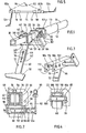
- FIGS. 1 and 2 has a carrier designated overall by 10 for preferably two subsoilers 12, of which only the left subsoiler is shown in Fig. 1, which - as will be explained in the following - follows the left one Tractor wheel is set.
- Fig. 2 shows schematically the arrangement of the right wheel mark eradicator.
- the carrier 10 consists in its central part of two telescopically guided tubes 13 and 14, through which the carrier 10 can be adjusted to the so-called lower link standard. Holders 16 and 18 (FIG. 5) are located on either side of this variable middle region.
- the left-hand holder 16 is followed by a pipe socket 13 which is fixedly connected to the holder 16 and into which a pipe 14 adapted to its inside diameter engages.
- the right bracket 18 can now either be firmly connected to this tube 14, which results in two non-interchangeable, different right and left assemblies, or the right assembly can also have a pipe socket 13, in which case the pipe 14 engages in both pipe sockets 13 as shown in FIG. 5.
- the pipe 14 can be in one of the two pipe sockets 13 e.g. be immovably fixed by a bolt.
- the brackets 16 and 18 each consist of two mutually parallel, vertically arranged plates 22 and 24 which are spaced apart to accommodate a lower link hook 20 (FIGS. 6-8) and which are joined together at their lower edge by a horizontal plate 26 U-shaped structures are added.
- a lower link hook 20 FIGS. 6-8
- mutually aligned bores 28 and 30 are provided which are suitable for receiving a bolt 32 (FIGS. 6-8) which can traverse a fastening bore in the lower link hook 20.
- the arrangement is such that the plate 26th from below on the lower link 34 (Fig. 6-8) when the bolt 32 passes through the bores 28 and 30 and the lower link hook 20, so that the carrier 10 is thereby firmly positioned and prevented from rotating about its longitudinal axis.
- a square tube 36 adjoins the outer plate 22, approximately as an extension of the pipe socket 13, and is provided with a group of vertical bores 38 arranged at regular intervals.
- a bearing saddle 40 for the subsoiler 12 is attached to the square tube 36 in a longitudinally displaceable manner.
- This bearing saddle in the embodiment according to FIGS. 1 and 2 consists of a section 42 of a square pipe enclosing the square tube 36, to the side of which two bearing cheeks 44 and 46 are attached, which project downward beyond section 42 and are flush with one another in this lower region Have holes 48 and 50 for a bearing pin 52.
- the bearing saddle 40 is traversed by a vertical bore 54 which can be aligned with one of the bores 38, so that the lateral position of the bearing saddle 40 can be determined by a plug bolt 56 passing through the bores 54 and 38, around the subsoiler 12 with respect to the wheel track of the vehicle or device carrying it.
- the subsoiler 12 consists of a flat coulter 58 which rises slightly counter to the direction of travel and transversely to it when the subsoiler 12 is in the working position. This loosens the soil by lifting and falling back and not by tearing open a deep channel.
- the coulter 58 is fastened to an arm 60 which is formed by a flat iron and which has a group of bores 62 arranged at regular intervals in its longitudinal direction.
- This arm 60 is assigned a bearing arm 64 which carries at one end a bearing sleeve 66 which is inserted between the two bearing cheeks 44 and 46 and is crossed by the bearing pin 52.
- the bearing pin 52 and the bearing sleeve 66 are rotatably connected to one another by a pin 68.
- the bearing arm 64 is provided with a bore 70 and with a greater radial distance from the bearing bolt 52 with a group of bores 72, the bores 72 being arranged concentrically with the bore 70.
- the arm 60 is fastened to the bearing arm 64 by two screws 74 and 76 which pass through two of the bores 62 and the bore 70 and one of the bores 72. Since the bores 72 are arranged concentrically to the bore 70, the setting angle of the blade 58 can be changed by selecting one of the bores 72, in particular e.g. the different lower link position caused by a device to be carried by the lower links.
- the screw 76 crossing one of the bores 72 can be designed as a shear-off screw, so that in the event of very strong resistance, the loosener can be pivoted backward about the screw 74 if the screw 76 is sheared off.
- the bearing pin 52 preferably protrudes from the bearing cheek 46 on the side facing away from the tractor, and the projecting section 52a is provided with a diametrical bore 80.
- a lever 82 with an axle sleeve 84 can be plugged onto the section 52a and connected in a rotationally fixed manner to the bearing bolt 52 and thus to the soil loosener 12 by a pin 88 passing through a bore 86 of the axle sleeve 84 and the bore 80.
- the lever 82 can e.g. via a shackle 90 with a tension member 92 (Fig. 5), e.g. a chain, which is connected at its other end to a similar lever 82 connected to the right soil loosener 12.
- a tension member 92 e.g. a chain
- the levers 82 and the tension member 92 are used when the device is attached to a towing vehicle which is connected to a reversible plow.
- a towing vehicle which is connected to a reversible plow.
- the tension member 92 is therefore attached with the levers 82 and connected to the plow frame, which can be rotated between the two working positions, at a location schematically designated by 94, the one subsoiler, in Fig.
- the left subsoiler 12b being assigned to the area already plowed and is lowered into the working position, while the right subsoiler 12a is assigned to the unploughed area and raised to its rest position. If the plow frame is rotated, the left subsoiler 12b is lifted and brought into the rest position by the tension member 92, while the right subsoiler 12a can sink under the influence of its weight into its working position, where it is pulled into the ground by the soil resistance until it 1, 2, 5 and 6 has reached the end position, in which the bearing arm 64 and the arm 60 are still pivoted outward by a certain angle from the vertical direction with respect to the center of the vehicle.
- this stop can be attached, for example, to the bearing cheek 44 facing away from the lever 82, the head 96 of the bearing bolt 52 resting on the outside of this bearing cheek 44 being designed as a stop lever which interacts with this stop 98.
- the head or stop lever 96 can be provided with a bore which is associated with a bore aligned with it in the rest position of the subsoiler 12 on the bearing cheek 44, so that the subsoiler 12 can be fixed in its raised rest position by inserting a pin.
- FIG. 3 and 4 show a variant of the embodiment described above, in which the structurally complex but very easy-to-use bearing of the subsoiler 12 is replaced by a releasable bearing bolt 100 via the bearing saddle 40, for its handling the square tube 36 by a U-profile 102, which is open at the bottom, is replaced, the legs of which are traversed by a series of bearing bores 104 and 106 arranged at equal distances from one another.
- the bearing arm 64 is aligned with the selected bore pair 104, 106 corresponding to the track width of the vehicle, then the bearing pin 100 is inserted and - unless a lever 82 is to be attached - secured by the pin 88. Finally, the bearing arm 64 is non-rotatably connected to the bearing pin 100 by the pin 68 so that the lever 82 can perform its function if necessary.
- the bearing can arm 64 can be extended beyond the bearing sleeve 66 in such a way that the extended section 64a abuts against the inner surface 108 of the upper crosspiece 110 of the U-profile 102 when the subsoiler 12 reaches its end position.
- This type of movement restriction for the subsoiler 12 can also be used in the embodiment according to FIGS. 1 and 2.
- a pair of bores 112, 114 can be provided in the side legs of the U-profile 102, into which a bolt can be inserted which supports the subsoiler 12 from below when it is in the inoperative position.
- plates 22 and 24 corresponding plates 122 and 124 are laterally attached to the pipe 13, which is longer than the examples described above, and instead of the horizontal plate 26 is on the narrow side facing away from the pipe 13 Plates 122 and 124 placed a vertically arranged plate 126.
- the plates 122 and 124 have aligned bores for receiving the bolt 32 passing through the lower link hook 20, which is fixed by a fuse 107.
- a bearing sleeve 111 is arranged, the inside diameter of which is adapted to the outside diameter of the tube 13, so that the bearing sleeve 111 can be displaced and rotated on the tube 13 to adjust the subsoiler 12 laterally and the angle of attack the coulter 58 to be able to change.
- the tube 13 is provided after the bracket 116 formed by the plates 122, 124 and 126 with a group of evenly spaced diametrical bores 117, in addition to the bearing sleeve 111 are axially and angularly offset, diametrical Bores 119 are provided, so that the subsoiler 12 can be fixed in a variety of positions by a pin 123 by selecting the appropriate pairings.
- a number of subsoilers 12 can be arranged next to one another on the right and on the left, in particular two subsoilers assigned to twin tires.
- the additional subsoiler 12 can simply be pushed onto the square tube 36 or tube 13 from the end or inserted into the U-profile 102 from below and fastened by a further bolt 52.
- the tubes can be slid 13 and 14 separately and then inserted between the brackets 116 more to the sleeve 111 provided subsoiler 12 g by corresponding borings s can be saved, after which the tubes 13 and 14 again are interconnected close thereto.
- the tubes 13 and 14 can be replaced by a square tube for receiving further bearing saddles 40, or in the example according to FIGS. 3 and 4 by a U-profile.
Landscapes
- Life Sciences & Earth Sciences (AREA)
- Engineering & Computer Science (AREA)
- Mechanical Engineering (AREA)
- Soil Sciences (AREA)
- Environmental Sciences (AREA)
- Soil Working Implements (AREA)
- Agricultural Machines (AREA)
Applications Claiming Priority (2)
| Application Number | Priority Date | Filing Date | Title |
|---|---|---|---|
| DE19843413517 DE3413517A1 (de) | 1984-04-10 | 1984-04-10 | Vorrichtung zur lockerung des untergrunds fuer landwirtschaftliche fahrzeuge und fahrbare geraete |
| DE3413517 | 1984-04-10 |
Publications (2)
| Publication Number | Publication Date |
|---|---|
| EP0158313A2 true EP0158313A2 (fr) | 1985-10-16 |
| EP0158313A3 EP0158313A3 (fr) | 1987-08-26 |
Family
ID=6233196
Family Applications (1)
| Application Number | Title | Priority Date | Filing Date |
|---|---|---|---|
| EP85104267A Withdrawn EP0158313A3 (fr) | 1984-04-10 | 1985-04-09 | Dispositif pour l'ameublissement du sous-sol adaptable sur véhicules agricoles et machines mobiles |
Country Status (2)
| Country | Link |
|---|---|
| EP (1) | EP0158313A3 (fr) |
| DE (1) | DE3413517A1 (fr) |
Cited By (2)
| Publication number | Priority date | Publication date | Assignee | Title |
|---|---|---|---|---|
| FR2621776A1 (fr) * | 1987-10-19 | 1989-04-21 | Soulard Raymond | Decompacteur de fond de raie |
| CN108934197A (zh) * | 2018-08-16 | 2018-12-07 | 江苏众创空间科技发展有限公司 | 一种改进型农机结构 |
Families Citing this family (1)
| Publication number | Priority date | Publication date | Assignee | Title |
|---|---|---|---|---|
| DE102022126126A1 (de) * | 2022-10-10 | 2024-04-11 | Amazonen-Werke H. Dreyer SE & Co. KG | Landwirtschaftliches Gerät mit Radspurlockerer |
Family Cites Families (6)
| Publication number | Priority date | Publication date | Assignee | Title |
|---|---|---|---|---|
| US2134438A (en) * | 1937-08-23 | 1938-10-25 | Click Clyde | Tractor attachment |
| DE1607463U (de) * | 1950-03-10 | 1950-06-01 | Paul Schweitzer Landmaschinen | Bodenbearbeitungsgeraet, insbesondere zur lockerung der radspuren von zugmaschinen u. dgl. |
| FR1024967A (fr) * | 1950-05-15 | 1953-04-09 | Tracteur | |
| US2691334A (en) * | 1950-07-11 | 1954-10-12 | Robert M Cannon | Tractor-tread track digger |
| CH329635A (de) * | 1955-06-07 | 1958-05-15 | Meyer Josef | Einrichtung an Ackerbau-Zugmaschinen zum Auflockern der Radspuren |
| FR1449049A (fr) * | 1965-07-02 | 1966-08-12 | Dispositif de sous-solage agissant au fond d'une raie de labour |
-
1984
- 1984-04-10 DE DE19843413517 patent/DE3413517A1/de not_active Withdrawn
-
1985
- 1985-04-09 EP EP85104267A patent/EP0158313A3/fr not_active Withdrawn
Cited By (2)
| Publication number | Priority date | Publication date | Assignee | Title |
|---|---|---|---|---|
| FR2621776A1 (fr) * | 1987-10-19 | 1989-04-21 | Soulard Raymond | Decompacteur de fond de raie |
| CN108934197A (zh) * | 2018-08-16 | 2018-12-07 | 江苏众创空间科技发展有限公司 | 一种改进型农机结构 |
Also Published As
| Publication number | Publication date |
|---|---|
| EP0158313A3 (fr) | 1987-08-26 |
| DE3413517A1 (de) | 1985-10-24 |
Similar Documents
| Publication | Publication Date | Title |
|---|---|---|
| DE2140410C3 (de) | An ein ziehendes Fahrzeug anschließbare Sämaschine | |
| EP0980643B1 (fr) | Suspension pour alésoir en ligne et sémoir ainsi équipé | |
| EP0679326A1 (fr) | Chariot trainé avec roues porteurs | |
| DE3105639A1 (de) | "geraetekombination fuer die landwirtschaft" | |
| DE69117842T2 (de) | Bodenbearbeitungsmaschine | |
| DE3105641C2 (fr) | ||
| DE2528930A1 (de) | Tragrahmen fuer landwirtschaftliche maschinen und geraete | |
| DE3033848A1 (de) | Kombinationsgeraet fuer die bodenbearbeitung | |
| DE68920222T2 (de) | Vorrichtung zum Schneiden von Rillen in den Boden. | |
| DE69419341T2 (de) | Bodenbearbeitungsmaschine | |
| DE2622444A1 (de) | Anbauvorrichtung fuer landwirtschaftliche verteilmaschinen | |
| EP0158313A2 (fr) | Dispositif pour l'ameublissement du sous-sol adaptable sur véhicules agricoles et machines mobiles | |
| EP0730816A1 (fr) | Construction de dent pour appareil agricole | |
| DE19633119A1 (de) | Landwirtschaftliche Bestellkombination | |
| DE2450386A1 (de) | Pflugsystem mit mehreren einzelpfluegen kontinuierlich einstellbarem abstand | |
| DE2010855B2 (de) | Maschine zum ausbringen von saatgut und duengemitteln | |
| DE2648528C2 (de) | Anbaurahmen für landwirtschaftliche Geräte, wie Ackerwalzen, Krümlerwalzen, Sägeräte, Hackeinrichtungen u.ä. | |
| DE69910683T2 (de) | Sähmaschine | |
| DE1482014B1 (de) | Maehvorrichtung,insbesondere zum Reinigen von Wassergraeben | |
| DE202021101060U1 (de) | Bodenbearbeitungsmaschine | |
| DE69616456T2 (de) | Drillmaschine | |
| DE3306650C2 (fr) | ||
| DE2015043A1 (de) | Bodenbearbeitungsgerät, insbeson dere Egge | |
| DE102010013470A1 (de) | Vorrichtung zum Verteilen von Saatgut und/oder Dünger | |
| DE3913226C2 (fr) |
Legal Events
| Date | Code | Title | Description |
|---|---|---|---|
| PUAI | Public reference made under article 153(3) epc to a published international application that has entered the european phase |
Free format text: ORIGINAL CODE: 0009012 |
|
| AK | Designated contracting states |
Designated state(s): AT BE CH FR IT LI NL |
|
| PUAL | Search report despatched |
Free format text: ORIGINAL CODE: 0009013 |
|
| AK | Designated contracting states |
Kind code of ref document: A3 Designated state(s): AT BE CH FR IT LI NL |
|
| 17P | Request for examination filed |
Effective date: 19880226 |
|
| 17Q | First examination report despatched |
Effective date: 19890829 |
|
| STAA | Information on the status of an ep patent application or granted ep patent |
Free format text: STATUS: THE APPLICATION IS DEEMED TO BE WITHDRAWN |
|
| 18D | Application deemed to be withdrawn |
Effective date: 19891103 |
|
| RIN1 | Information on inventor provided before grant (corrected) |
Inventor name: NIEDERMEIR, FRANZ Inventor name: GASSNER, JOHANN |