EP0158521A2 - Jardinière pour cloisons de séparation - Google Patents
Jardinière pour cloisons de séparation Download PDFInfo
- Publication number
- EP0158521A2 EP0158521A2 EP85302399A EP85302399A EP0158521A2 EP 0158521 A2 EP0158521 A2 EP 0158521A2 EP 85302399 A EP85302399 A EP 85302399A EP 85302399 A EP85302399 A EP 85302399A EP 0158521 A2 EP0158521 A2 EP 0158521A2
- Authority
- EP
- European Patent Office
- Prior art keywords
- planter
- bracket
- container
- wall
- partition
- Prior art date
- Legal status (The legal status is an assumption and is not a legal conclusion. Google has not performed a legal analysis and makes no representation as to the accuracy of the status listed.)
- Withdrawn
Links
Images




Classifications
-
- A—HUMAN NECESSITIES
- A47—FURNITURE; DOMESTIC ARTICLES OR APPLIANCES; COFFEE MILLS; SPICE MILLS; SUCTION CLEANERS IN GENERAL
- A47H—FURNISHINGS FOR WINDOWS OR DOORS
- A47H27/00—Boxes, shelves, holders or similar supports for holding flowers
-
- A—HUMAN NECESSITIES
- A47—FURNITURE; DOMESTIC ARTICLES OR APPLIANCES; COFFEE MILLS; SPICE MILLS; SUCTION CLEANERS IN GENERAL
- A47G—HOUSEHOLD OR TABLE EQUIPMENT
- A47G7/00—Flower holders or the like
- A47G7/02—Devices for supporting flower-pots or cut flowers
- A47G7/04—Flower tables; Stands or hangers, e.g. baskets, for flowers
- A47G7/044—Hanging flower-pot holders, e.g. mounted on walls, balcony fences or the like
-
- E—FIXED CONSTRUCTIONS
- E04—BUILDING
- E04B—GENERAL BUILDING CONSTRUCTIONS; WALLS, e.g. PARTITIONS; ROOFS; FLOORS; CEILINGS; INSULATION OR OTHER PROTECTION OF BUILDINGS
- E04B2/00—Walls, e.g. partitions, for buildings; Wall construction with regard to insulation; Connections specially adapted to walls
- E04B2/74—Removable non-load-bearing partitions; Partitions with a free upper edge
Definitions
- the present invention relates to containers for plants and other decorative objects.
- the present invention relates to containers capable of being mounted upon or supported by wall partitions such as those frequently employed in offices.
- U.S. Patent 4,015,543 to Stankowitz discloses a support bracket designed to be mounted between and supported by wall partitions.
- the support bracket is perpendicular to the wall partitions and receives an octagonal saucer, upon which plants and other decorative objects can be placed. These objects project a substantial distance from the partition walls, and if employed in work stations, would merely serve to make crowded conditions worse.
- the support bracket is incapable of supporting anything except the lightest of objects, such that heavy plants could not be placed upon the saucer.
- U.S. Patent 4,415,091 to Wolff discloses a plurality of wall partitions joined together at their vertical edges. A beam member is supported at each of its end edges with a hanger which is inserted between the wall partitions where they join together.
- Various types of racks are designed to be securely suspended from one or more beams, yielding an unlimited number of combinations of racks for any purpose desired. The racks project a substantial distance from the partition walls, and if employed in work stations, would serve to make crowded conditions worse.
- the present invention concerns mounting a planter upon a partition wall in such a manner that it projects into the work station only a slight distance compared to prior art devices. Specifically, the present invention mounts a planter on top of a partition wall or against a partition wall such that the planter slightly projects into a work station.
- the invention includes a planter adapted to be mounted on top of a partition wall by means of brackets or by means of a groove formed in the planter itself, such that the planter straddles the top of the partition wall.
- the invention also includes a planter adapted to mount against a partition wall by means of brackets or by means of an extension of the planter designed to hook over the top of the partition wall.
- the planters of the present invention are designed to mount on top of or against a partition wall such as is normally found in modern offices.
- the planters can be any shape, but the preferred shape is either rectangular, as shown in Figures 1, 2, 5, 6, 9-13, and 17-24 or round as shown in Figures 14 -16.
- rectangular planters come in sizes which correspond to widths of wall partitions, for example, 18, 24 or 36 inches, or the planters may be slightly larger than the partition width as illustrated specifically in Figure 5.
- the planters generally have an unobstructed interior for containing soil and plants, which retains any moisture.
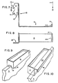
- the planter can be supported by means of a bracket as illustrated in Figures 1 - 8 and 16-24, or the planter can be self supporting as illustrated in Figures 9 - 15.
- the bracket design can be of the type made to fit on top of the partition wall as shown in Figures 1 - 4, and 17-24 or the type designed to mount between partition walls as shown in Figures 5 - 8.
- the planter is self supporting, it can be provided with a groove on its bottom surface as shown in Figures 9 and 14, or it can be provided with an integral hook arm as illustrated in Figures 10 and 11, or it can be of the saddle bag type designed to straddle the top of a partition wall as shown in Figures 12, 13 and 15.
- the planter may be made of any conventional material such as metal, plastic, synthetic resin or wood. If a metal is used to make the planter, preferably a non-oxidizing metal is employed like stainless steel, bronze, copper, aluminum or brass, with a brushed or satin texture being preferred. If plastic is employed to make the planter, plastics that can be molded or die cast are preferred. Suitable plastics may be employed such as ABS, acrylic, polystyrene, polyethylene, polyvinylchloride, polytetrafluoroethylene (teflon), polymethyl methacrylate (plexiglas or lucite), polypropylene, polycarbonate, or the like.
- Synthetic resins may also be employed to make the planter, such as nylon, rayon, dacron, formica, fiberglas, polyester, phenol formaldehyde, phenol-furfural, urea formaldehyde, and the like.
- the plastics can include color pigments, fire retardants, gloss agents, etc. as is well known to those skilled in the art. If wood is employed, preferably the wood is treated or coated, for example, with a plastic or paint, to prevent rot and retain moisture for the plants., Also a wood veneer, or a paper or fabric covering, could be employed on a planter which is made of metal, plastic, synthetic resin, or the like.
- Figure 1 shows an end view of a typical partition wall 3, with a support bracket 2 designed to fit on top of the partition wall 3, and a rectangular planter 1 supported by one or more brackets 2.
- Figure 2 shows a perspective view of the rectangular planter 1 supported by two brackets.
- the planter could also be circular as illustrated in Figure 16 by reference numeral 28.
- the support bracket 29 is similar to bracket 2, but has upwardly projecting end portions 30 which are round to conform to the shape of the circular planter 28.
- the bracket may be the one-piece type or a two-piece slide type designed so that one size fits all. Because most partition walls are 1-1/2" to 3" wide, the grips of the bracket which fit around the top wall are also designed for this width.
- the use of a slide type bracket eliminates the need of retaining many different size one-piece brackets.
- the brackets may be made of plastic, metal, resins, or the like, so long as the material is sufficient in strength to rigidly mount the planter.
- Bracket 2 which includes a base portion 8, with upwardly projecting end portions 4 and 5, spaced apart a sufficient distance to fit the width of rectangular planter 1.
- the bracket is tightly held upon the top width portion of the partition wall 3 by means of bottom grips 6 and 7.
- Grips 6 and 7 are integrally formed with the base portion 8 on the side opposite the side of the upwardly projecting end portions 4 and 5.
- the planter may be supported by brackets against the side of partition wall 3 as shown in Figures 5 and 6.
- the brackets 9 are made for insertion between the panels of the partition wall, and consequently, planter 1 must be about the same size as a panel, or preferably slightly longer than the width of a panel.
- the bracket 9, as shown in Figures 7 and 8, comprises angle iron having an insert portion 10, and a perpendicular wall section 12.
- the inserted portion 10 includes some type of fastening means 11 which generally comprise one or more hook members.
- the fastening means 11 depend upon the type of wall partition employed. Typically, wall partitions are held together by means of quick threaded or double threaded screws to permit fast assembly and disassembly of the partition wall panels.
- Fastening means 11 is designed to hook on, or otherwise quickly attach to, the screws holding the wall partition together by placing the insert portion 10 between the panels of the wall partitions, so that fastening means 11 may be secured by the screws.
- the bracket 9 also includes a base member 13 designed to physically hold the planter, along with an upwardly projecting end portion 14 adapted to prevent planter 1 from sliding away from the partition wall 3 and sliding off bracket 9. End portions 14 may include a cushion or pad 14A to prevent scratching the planter.
- Planter 15 illustrated in Figure 9 straddles wall partition 3 and is self-supporting.
- the bottom wall 16 of planter 15 includes a grooved portion 17 which is of sufficient width and height to support the planter.
- the groved portion 17 produces a raised floor in the interior of the planter along with two longitudinal troughs.
- the troughs are designed to drain excess water away from the plants.
- This type of planter is preferably made of plastic because it can easily be manufactured by molding or die casting techniques.
- Figure 14 illustrates a planter 24 similar to that illustrated in Figure 9, but is circular in shape.
- Bottom surface 25 including groove 26, is adapted to mate with the top portion of wall partition 3 to support the planter.
- the interior bottom surface of planter 24 produces a raised floor with corresponding troughs as described with respect to Figure 9.
- the planter need not be positioned immediately above the top of the partition wall, but may be offset as shown in Figures 10 - 13 and 15.
- a single rectangular planter 18 and 21 is illustrated in Figures 10 and 11, respectively.
- Each planter is supported by a horizontal arm 20 with a perpendicular downwardly projecting component 19.
- Horizontal arm 20 is attached to planter 18 at the top lip of the planter as shown in Figure 10.
- Horizontal arm 20 is attached to planter 21 approximately midway along the back side wall of the planter such that the planter projects substantially above the top of the partition wall.
- Figures 12, 13 and 15 illustrate a saddle bag type arrangement where two planters tightly straddle the top of the partition wall.
- two planters 22 and 23, respectively, are integrally connected with a horizontal arm 20.
- Figure 12 shows horizontal arm 20 connecting the pair of planters 22 midway along the longitudinal wall of each planter which bears directly against partition wall 3. In this manner, planters 22 project substantially above the top of the partition wall.
- Figure 13 shows horizontal arm 20 connecting planters 23 adjacent the lip of each planter. This arrangement maintains a profile approximately the height of the partition wall.
- Figure 15 is similar to the planter shown in Figure 13, except that the planters 27 are round and integrally attached by a horizontal segment 26.
- the segment 26 is attached adjacent the lip of planters 27 as disclosed with respect to the planters 23 illustrated in Figure 13.
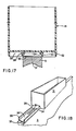
- Figures 17 and 18 illustrate a slide system for supporting planter 31 atop wall partition 3.
- Planter 31 has two longitudinal slide grooves projecting downwardly from the bottom, underneath side of the planter. Each slide groove is formed from a pair of downwardly projecting arms 33 and 34. Arm 33 is generally longer than arm 34 and arm 34 generally terminates in a bulbous edge.
- Slide bracket 36 is firmly attached atop wall partition 3 by means of adhesive tape 37, or the like.
- Slide bracket 36 includes upwardly projecting side walls 38, both of which terminate in a bulbous edge portion, each edge portion directed toward the other.
- planter 40 includes a series of ears 44 projecting inwardly from each end wall of the planter. Each ear is spaced apart a distance slightly greater than the thickness of spring clip 39.
- Spring clip 39 includes a flexible curved lateral end 41 and a lateral U-shaped hook end 43. As shown in the exploded view of Figure 19, spring clip 39 is placed over the top of wall partition 3 such that lateral end 41 is pressed tightly against the side of wall partition 3. Next, planter 40 is held adjacent the top portion of wall partition 3, permitting spring clip 39 to project into the interior of the planter. Then the spring clip 39 is moved toward an end wall of the planter such that U-shaped hook 43 engages an ear 44. This arrangement permits the planter 40 to accomodate many different thicknesses of wall partitions.
- curved lateral end 41 may include a cushion 42, which also contributes to the resiliency of spring clip 39, insofar as its ability to accomodate many different thicknesses of wall partitions.
- FIG. 21-24 A preferred method of mounting a planter atop a partition wall 3 is illustrated by Figures 21-24. This method is preferred for top mounting because the brackets fit most all the common thicknesses of wall partitions and because this system permits mounting the planter adjacent a wall of the building, when the wall partition is mounted adjacent the wall of the building.
- Planter 45 includes a circumferential skirt 46 to hide the mounting system for aesthetic purposes.
- the planter also includes a raised floor 47, which permits drainage in troughs 48, just as incorporated with the Figures 9 and 14 planters.
- the interior side wall of planter 45 includes a tapered wall 49 which terminates into troughs 48.
- the tapered wall 49 and circumferential skirt 46 create a longitudinal slot beneath the bottom of the planter for upwardly projecting member 50.
- the mounting system comprises two L-shaped brackets 52 and 53.
- Two threaded studs 54 are securely and integrally fastened to bracket 53.
- the studs 54 may be welded, glued, press fitted, or the like onto bracket 53.
- Bracket 52 is much longer than bracket 53 and has a longitudinal slot 57 as illustrated in Figure 22.
- a planter bracket 51 includes a longitudinal slot 56 with an upwardly projecting member 50 at each end, which fit into corresponding longitudinal slots formed by the planter as previously explained.
- brackets 52 and 53 are placed atop wall partition 3 and are adjustable to fit walls 1-1/2 to 3" thick.
- the wall illustrated in Figure 21 represents a 3" thick wall 3. If the wall were 1-1/2" thick, bracket 52, would extend beyond the vertical portion of bracket 53, as shown in Figure 21, but would not extend to circumferential skirt 46.
- planter bracket 51 is placed over the top L-shaped bracket 52 such that studs 54 extend through slot 57 of bracket 52, and extend through slot 56 of planter bracket 51.
- the planter bracket is positioned such that one end is flush with the vertical end of bracket 52, and the other end projects out beyond wall partition 3.
- bracket system could include a fourth bracket, which would be a mere flat plate.
- This fourth bracket would include the studs 54, and it would be positioned on top of the upper surface of wall partition 3. Since the fourth bracket includes the studs, bracket 53 will not include studs, but will merley have a longitudinal slot like bracket 52. This system is not as desirable because the fourth bracket is expendable and unnecessary.
Landscapes
- Engineering & Computer Science (AREA)
- Architecture (AREA)
- Physics & Mathematics (AREA)
- Electromagnetism (AREA)
- Civil Engineering (AREA)
- Structural Engineering (AREA)
- Cultivation Receptacles Or Flower-Pots, Or Pots For Seedlings (AREA)
- Details Of Rigid Or Semi-Rigid Containers (AREA)
Applications Claiming Priority (2)
| Application Number | Priority Date | Filing Date | Title |
|---|---|---|---|
| US598367 | 1984-04-09 | ||
| US06/598,367 US4559738A (en) | 1984-04-09 | 1984-04-09 | Top sider planter |
Publications (2)
| Publication Number | Publication Date |
|---|---|
| EP0158521A2 true EP0158521A2 (fr) | 1985-10-16 |
| EP0158521A3 EP0158521A3 (fr) | 1986-05-14 |
Family
ID=24395276
Family Applications (1)
| Application Number | Title | Priority Date | Filing Date |
|---|---|---|---|
| EP85302399A Withdrawn EP0158521A3 (fr) | 1984-04-09 | 1985-04-04 | Jardinière pour cloisons de séparation |
Country Status (5)
| Country | Link |
|---|---|
| US (1) | US4559738A (fr) |
| EP (1) | EP0158521A3 (fr) |
| JP (1) | JPS60227613A (fr) |
| AU (1) | AU4095285A (fr) |
| CA (1) | CA1274690A (fr) |
Cited By (1)
| Publication number | Priority date | Publication date | Assignee | Title |
|---|---|---|---|---|
| DE29715456U1 (de) * | 1997-08-28 | 1997-12-11 | Dorenwendt, Wolfgang, 37359 Wachstedt | Blumenkastenhalter aus Strangpreßprofil |
Families Citing this family (61)
| Publication number | Priority date | Publication date | Assignee | Title |
|---|---|---|---|---|
| USD312983S (en) | 1988-03-28 | 1990-12-18 | Powell Alfred J | Modular planter trough |
| USD316835S (en) | 1988-07-06 | 1991-05-14 | Alyce Ginsberg | Partition planter |
| US4912876A (en) * | 1988-07-06 | 1990-04-03 | Alyce Ginsberg | Partition wall planter |
| USD315653S (en) | 1988-07-25 | 1991-03-26 | Truffa Steven L | Tub and shower shelf |
| USD313374S (en) | 1988-09-19 | 1991-01-01 | Hartley Shirley A | Dual planter box |
| USD316058S (en) | 1988-12-21 | 1991-04-09 | Mitchell Deryl K | Rail-mountable planter |
| US5072542A (en) * | 1989-12-29 | 1991-12-17 | Doyle Quackenbush | Gravestone saddle planter |
| USD337938S (en) | 1990-03-16 | 1993-08-03 | Donald Shaw | Bracket for a planter box |
| US5177899A (en) * | 1990-12-20 | 1993-01-12 | Powell A J | Modular planter trough with stabilized mounting bracket |
| US5269095A (en) * | 1991-07-11 | 1993-12-14 | Topsiders, Inc. | Planter mounting assembly |
| USD344650S (en) | 1992-08-13 | 1994-03-01 | Arcularius William H | Towel rack |
| USD367243S (en) | 1995-04-04 | 1996-02-20 | Akryl Industries Inc. | Planter for mounting on railing |
| USD385213S (en) * | 1996-04-29 | 1997-10-21 | Akryl Industries Inc. | Elongate planter for mounting along railing |
| US5887384A (en) * | 1996-07-08 | 1999-03-30 | Zaremba; George Julian | Panel planter |
| US6108971A (en) * | 1996-07-08 | 2000-08-29 | Zaremba; George Julian | Panel planter |
| FR2753340B1 (fr) * | 1996-09-17 | 1999-01-22 | Sistac Sa B | Dispositif pour contenir et suspendre une charge d'un materiau, par exemple pot de fleur |
| FR2753339B1 (fr) * | 1996-09-17 | 1998-10-23 | Sistac Sa B | Dispositif pour contenir et suspendre une charge d'un materiau, par exemple pot de fleur |
| US5822918A (en) * | 1996-11-25 | 1998-10-20 | Barbara Helfman | Planter |
| US5984249A (en) * | 1997-03-28 | 1999-11-16 | Vista Products | Support for mounting containers without requiring tools |
| US6012690A (en) * | 1997-03-28 | 2000-01-11 | Vista Products, Inc. | Support for mounting containers without requiring tools |
| FR2774576B1 (fr) * | 1998-02-06 | 2000-04-28 | Bouillard Freres | Jardiniere autonome ou similaire, notamment pour la decoration florale de balcons et de terrasses |
| US6079686A (en) * | 1998-06-23 | 2000-06-27 | Reed; Dewayne | Tray support apparatus |
| US7096519B2 (en) * | 2002-06-07 | 2006-08-29 | Susan Ferreri | Shelf for shower enclosure |
| CA2478602A1 (fr) * | 2003-08-20 | 2005-02-20 | Ltl Wholesale, Inc. D.B.A. Ltl Home Products, Inc. | Dispositif de fixation de lissage |
| US20050178059A1 (en) * | 2004-02-12 | 2005-08-18 | Braun J. R. | Hanging in-rail planter for deck & porch railings |
| US20060191196A1 (en) * | 2005-02-28 | 2006-08-31 | Bradley Cochran | Planter and a planter assembly |
| GB2434292B (en) * | 2005-11-18 | 2010-07-21 | Glasdon Ltd | A planter |
| US20080149578A1 (en) * | 2006-12-26 | 2008-06-26 | Jonathan Scharf | Utility organizer for use on a deck rail |
| US20090064573A1 (en) * | 2007-09-12 | 2009-03-12 | John Braun | Flower planter for railings and fences |
| US8671613B2 (en) * | 2008-03-11 | 2014-03-18 | Michael G. Crilly | Tree slide |
| KR101133035B1 (ko) * | 2009-04-09 | 2012-04-09 | 김가우 | 고정식 클램프가 구비된 화분 |
| US20110010990A1 (en) * | 2009-07-17 | 2011-01-20 | Darrell Harvey Richardson | Device and Method for Rooting and/or Dormancy for Plant Bulbs |
| US20120068027A1 (en) * | 2009-12-30 | 2012-03-22 | Cnd Products Llc | Device for holding packages |
| AU2010340293A1 (en) * | 2010-01-06 | 2012-08-02 | Spin Free L.L.C. | Method and apparatus for stabilizing a mixing bucket |
| US9185974B2 (en) | 2010-06-02 | 2015-11-17 | Steelcase Inc. | Frame type workstation configurations |
| US8667908B2 (en) | 2010-06-02 | 2014-03-11 | Steelcase Inc. | Frame type table assemblies |
| US8534752B2 (en) | 2010-06-02 | 2013-09-17 | Steelcase Inc. | Reconfigurable table assemblies |
| US9210999B2 (en) | 2010-06-02 | 2015-12-15 | Steelcase Inc. | Frame type table assemblies |
| US8844210B2 (en) * | 2011-01-04 | 2014-09-30 | Kimball International, Inc. | Upmount overhead brackets for office partition systems |
| USD649807S1 (en) | 2011-04-22 | 2011-12-06 | Steelcase Inc. | Shelf |
| US8561355B2 (en) * | 2011-05-10 | 2013-10-22 | Mark Canavarro | System for extending the height of cubicle walls |
| US8967054B2 (en) | 2011-06-03 | 2015-03-03 | Kimball International, Inc. | Office desking system |
| US20150000189A1 (en) * | 2012-02-01 | 2015-01-01 | Noga Greis-Avnon | Railing planter |
| US12376677B1 (en) | 2012-10-10 | 2025-08-05 | Steelcase Inc. | Ergonomic seating system, tilt-lock control and remote powering method and apparatus |
| USD771403S1 (en) * | 2014-07-22 | 2016-11-15 | Who-Rae Australia, Llc | Hanger container for car floor mats |
| US9149006B1 (en) * | 2015-02-18 | 2015-10-06 | Albert J. Pope | Garden made EZ modular planter device |
| WO2017072365A1 (fr) * | 2015-10-30 | 2017-05-04 | Syngenta Participations Ag | Récipient de plante et système de plateau |
| US10517392B2 (en) | 2016-05-13 | 2019-12-31 | Steelcase Inc. | Multi-tiered workstation assembly |
| WO2017197395A1 (fr) | 2016-05-13 | 2017-11-16 | Steelcase Inc. | Ensemble station de travail multiniveaux |
| CA3073520A1 (fr) * | 2017-08-25 | 2019-02-28 | Syll Innovations, Llc | Dispositifs et systemes de suspension de fenetre a patin de compression |
| EP3914128A4 (fr) | 2019-01-24 | 2022-10-26 | Steelcase Inc. | Système de support d'affichage et son procédé d'utilisation |
| CN110292282B (zh) * | 2019-07-15 | 2024-06-28 | 李�和 | 一种办公桌隔板花架 |
| CA3107296A1 (fr) | 2020-02-14 | 2021-08-14 | The Hc Companies, Inc. | Contenant d`horticulture montable sur un garde-fou |
| USD938302S1 (en) | 2020-02-20 | 2021-12-14 | The Hc Companies, Inc. | Planter |
| USD951136S1 (en) * | 2020-05-11 | 2022-05-10 | Gerald Johnson | Flowerpot with soil anchor |
| WO2022020136A1 (fr) | 2020-07-23 | 2022-01-27 | Steelcase Inc. | Système de support d'affichage et procédé d'utilisation associé |
| US10989237B1 (en) * | 2020-09-04 | 2021-04-27 | Robert J. Wittsche | System for extending the height of cubicle wall panel |
| US11918134B2 (en) * | 2021-01-27 | 2024-03-05 | ARME Solutions, LLC | Article for use in mounting associated articles to vertical planar members such as fences |
| US11317743B1 (en) | 2021-07-15 | 2022-05-03 | Sam S. Saman | Railing bracket holder and systems, kits, and methods thereof |
| US12042072B2 (en) * | 2021-10-01 | 2024-07-23 | John Edward Aiken | Trellis bracket and system for supporting climbing plants from top of a wall or fence on both sides |
| USD1099815S1 (en) * | 2023-04-19 | 2025-10-28 | LCI Italy s.r.l. | Support for a table for trains |
Family Cites Families (22)
| Publication number | Priority date | Publication date | Assignee | Title |
|---|---|---|---|---|
| US1353853A (en) * | 1920-04-16 | 1920-09-28 | August P Sandberg | Bracket |
| US1852650A (en) * | 1929-08-07 | 1932-04-05 | Halberstadter Juda | Support for flowerpots and the like |
| US1955476A (en) * | 1932-03-25 | 1934-04-17 | Torgersen Ralph | Flower box holder |
| US2971805A (en) * | 1956-02-29 | 1961-02-14 | Martin S Weiss | Modular cabinet structure and components used therein |
| US2896893A (en) * | 1956-04-16 | 1959-07-28 | Oliver Mariano | Accessory for venetian blinds |
| US3027014A (en) * | 1961-01-24 | 1962-03-27 | Gadget Of The Month Club Inc | Mounting device for decorative items |
| US3664626A (en) * | 1970-07-30 | 1972-05-23 | Valley Decorating Co | Bracket for mounting decorations on a building front |
| FR2231309A1 (en) * | 1973-05-28 | 1974-12-27 | Dussy Jean Francois | Window box for balcony balustrades - has two containers connected by strip hanging on either side of balustrade rail |
| US3871144A (en) * | 1973-09-28 | 1975-03-18 | Form Space Corp | Modular environment structuring apparatus |
| US4015543A (en) * | 1974-10-29 | 1977-04-05 | Stankowitz Arthur J | Platform support structure |
| FR2340073A1 (fr) * | 1976-02-04 | 1977-09-02 | Bouillard Rene | Support de balconniere |
| US4062147A (en) * | 1976-04-07 | 1977-12-13 | Phillips Ronald L | Horticultural container assembly with saucer drainage and ventilation passage |
| DE7635182U1 (de) * | 1976-11-06 | 1977-05-18 | Mehlhose, Dietrich, 4900 Herford | Pflanzen-aufnahmebehaelter |
| AT348814B (de) * | 1977-03-16 | 1979-03-12 | Ferenczy Kurt | Einrichtung zur aufnahme und lagerung von erde od. dgl. |
| DE7723426U1 (de) * | 1977-07-27 | 1977-12-08 | Fa. Richard Heinze, 4900 Herford | Blumenkasten zum aufhaengen an mauern und gelaendern |
| US4137668A (en) * | 1977-10-25 | 1979-02-06 | Dairoku Kojo | Flower-pot |
| USD257993S (en) | 1978-11-30 | 1981-01-20 | LeRoy M. Lefkowitz | Wall or partition hung in/out tray |
| US4315382A (en) * | 1979-11-26 | 1982-02-16 | Phillips Petroleum Co. | Plant container |
| US4415091A (en) * | 1981-06-01 | 1983-11-15 | Wolff Wire Corporation | Accessories for movable partition systems |
| FR2510349B1 (fr) * | 1981-07-31 | 1986-08-14 | Famy Marcel | Pots de fleurs ou analogues a accrochage automatique |
| DE8126460U1 (de) * | 1981-09-11 | 1982-03-18 | Lotz, Joachim, 5303 Bornheim | Blumenkastenhalte fuer dachbalkone |
| FR2520218B1 (fr) * | 1982-01-22 | 1986-07-11 | Manuf Proven Matieres Plas | Dispositif de supports balconnieres reglables |
-
1984
- 1984-04-09 US US06/598,367 patent/US4559738A/en not_active Expired - Lifetime
-
1985
- 1985-04-04 CA CA000478390A patent/CA1274690A/fr not_active Expired - Lifetime
- 1985-04-04 EP EP85302399A patent/EP0158521A3/fr not_active Withdrawn
- 1985-04-09 AU AU40952/85A patent/AU4095285A/en not_active Abandoned
- 1985-04-09 JP JP60073659A patent/JPS60227613A/ja active Pending
Cited By (1)
| Publication number | Priority date | Publication date | Assignee | Title |
|---|---|---|---|---|
| DE29715456U1 (de) * | 1997-08-28 | 1997-12-11 | Dorenwendt, Wolfgang, 37359 Wachstedt | Blumenkastenhalter aus Strangpreßprofil |
Also Published As
| Publication number | Publication date |
|---|---|
| CA1274690A (fr) | 1990-10-02 |
| EP0158521A3 (fr) | 1986-05-14 |
| AU4095285A (en) | 1985-10-17 |
| US4559738A (en) | 1985-12-24 |
| JPS60227613A (ja) | 1985-11-12 |
Similar Documents
| Publication | Publication Date | Title |
|---|---|---|
| US4559738A (en) | Top sider planter | |
| US4698936A (en) | Partition wall planter | |
| US20080136301A1 (en) | Tool and utensil stowage system | |
| US5458243A (en) | Multiple stack-tray assembly | |
| US6012690A (en) | Support for mounting containers without requiring tools | |
| US5822918A (en) | Planter | |
| US4708310A (en) | Corner mounted tray | |
| US5984249A (en) | Support for mounting containers without requiring tools | |
| US3858725A (en) | Tennis equipment rack | |
| US4450655A (en) | Vertically slotted panel | |
| US5177899A (en) | Modular planter trough with stabilized mounting bracket | |
| US5246105A (en) | Modular container for dental photocuring materials | |
| US3955786A (en) | Miniature magnetic base flagstaff assembly for vehicle bodies | |
| CA2089138A1 (fr) | Etagere portative | |
| US4475306A (en) | Window sill flower pot support | |
| US5114106A (en) | Universal container holding device | |
| US11602220B1 (en) | Flexible hook hanger for mounting on a curved surface | |
| US5327676A (en) | Corner pot holder apparatus | |
| US20020074462A1 (en) | Combination garden hose hanger and storage device | |
| US20210221564A1 (en) | Modular container | |
| US4177901A (en) | Bathroom wall fixture | |
| US4796845A (en) | Support device for modular wall unit | |
| US4581858A (en) | Hutch divider | |
| US4674139A (en) | Unitary wall-mounted sink | |
| US6371035B1 (en) | Storage device |
Legal Events
| Date | Code | Title | Description |
|---|---|---|---|
| PUAI | Public reference made under article 153(3) epc to a published international application that has entered the european phase |
Free format text: ORIGINAL CODE: 0009012 |
|
| AK | Designated contracting states |
Designated state(s): DE FR GB SE |
|
| PUAL | Search report despatched |
Free format text: ORIGINAL CODE: 0009013 |
|
| AK | Designated contracting states |
Kind code of ref document: A3 Designated state(s): DE FR GB SE |
|
| 17P | Request for examination filed |
Effective date: 19861010 |
|
| 17Q | First examination report despatched |
Effective date: 19871127 |
|
| STAA | Information on the status of an ep patent application or granted ep patent |
Free format text: STATUS: THE APPLICATION IS DEEMED TO BE WITHDRAWN |
|
| 18D | Application deemed to be withdrawn |
Effective date: 19890523 |