EP0158811A2 - Führung, insbesondere für auskippbare Möbelteile - Google Patents
Führung, insbesondere für auskippbare Möbelteile Download PDFInfo
- Publication number
- EP0158811A2 EP0158811A2 EP85102687A EP85102687A EP0158811A2 EP 0158811 A2 EP0158811 A2 EP 0158811A2 EP 85102687 A EP85102687 A EP 85102687A EP 85102687 A EP85102687 A EP 85102687A EP 0158811 A2 EP0158811 A2 EP 0158811A2
- Authority
- EP
- European Patent Office
- Prior art keywords
- strips
- rail
- outer rail
- guide according
- inner rail
- Prior art date
- Legal status (The legal status is an assumption and is not a legal conclusion. Google has not performed a legal analysis and makes no representation as to the accuracy of the status listed.)
- Granted
Links
Images
Classifications
-
- A—HUMAN NECESSITIES
- A47—FURNITURE; DOMESTIC ARTICLES OR APPLIANCES; COFFEE MILLS; SPICE MILLS; SUCTION CLEANERS IN GENERAL
- A47B—TABLES; DESKS; OFFICE FURNITURE; CABINETS; DRAWERS; GENERAL DETAILS OF FURNITURE
- A47B88/00—Drawers for tables, cabinets or like furniture; Guides for drawers
- A47B88/40—Sliding drawers; Slides or guides therefor
- A47B88/483—Sliding drawers; Slides or guides therefor with single extensible guides or parts
- A47B88/487—Sliding drawers; Slides or guides therefor with single extensible guides or parts with rollers, ball bearings, wheels, or the like
-
- A—HUMAN NECESSITIES
- A47—FURNITURE; DOMESTIC ARTICLES OR APPLIANCES; COFFEE MILLS; SPICE MILLS; SUCTION CLEANERS IN GENERAL
- A47B—TABLES; DESKS; OFFICE FURNITURE; CABINETS; DRAWERS; GENERAL DETAILS OF FURNITURE
- A47B88/00—Drawers for tables, cabinets or like furniture; Guides for drawers
- A47B88/40—Sliding drawers; Slides or guides therefor
- A47B88/407—Adjustably or detachably mounted drawers
-
- A—HUMAN NECESSITIES
- A47—FURNITURE; DOMESTIC ARTICLES OR APPLIANCES; COFFEE MILLS; SPICE MILLS; SUCTION CLEANERS IN GENERAL
- A47B—TABLES; DESKS; OFFICE FURNITURE; CABINETS; DRAWERS; GENERAL DETAILS OF FURNITURE
- A47B88/00—Drawers for tables, cabinets or like furniture; Guides for drawers
- A47B88/40—Sliding drawers; Slides or guides therefor
- A47B88/49—Sliding drawers; Slides or guides therefor with double extensible guides or parts
- A47B88/493—Sliding drawers; Slides or guides therefor with double extensible guides or parts with rollers, ball bearings, wheels, or the like
-
- A—HUMAN NECESSITIES
- A47—FURNITURE; DOMESTIC ARTICLES OR APPLIANCES; COFFEE MILLS; SPICE MILLS; SUCTION CLEANERS IN GENERAL
- A47B—TABLES; DESKS; OFFICE FURNITURE; CABINETS; DRAWERS; GENERAL DETAILS OF FURNITURE
- A47B2210/00—General construction of drawers, guides and guide devices
- A47B2210/0002—Guide construction for drawers
- A47B2210/0029—Guide bearing means
- A47B2210/0032—Balls
- A47B2210/0035—Balls cages therefor, e.g. for telescopic slides
-
- A—HUMAN NECESSITIES
- A47—FURNITURE; DOMESTIC ARTICLES OR APPLIANCES; COFFEE MILLS; SPICE MILLS; SUCTION CLEANERS IN GENERAL
- A47B—TABLES; DESKS; OFFICE FURNITURE; CABINETS; DRAWERS; GENERAL DETAILS OF FURNITURE
- A47B2210/00—General construction of drawers, guides and guide devices
- A47B2210/0002—Guide construction for drawers
- A47B2210/0051—Guide position
- A47B2210/0056—Guide located at the bottom of the drawer
-
- A—HUMAN NECESSITIES
- A47—FURNITURE; DOMESTIC ARTICLES OR APPLIANCES; COFFEE MILLS; SPICE MILLS; SUCTION CLEANERS IN GENERAL
- A47B—TABLES; DESKS; OFFICE FURNITURE; CABINETS; DRAWERS; GENERAL DETAILS OF FURNITURE
- A47B2210/00—General construction of drawers, guides and guide devices
- A47B2210/0002—Guide construction for drawers
- A47B2210/0051—Guide position
- A47B2210/0059—Guide located at the side of the drawer
Definitions
- drawer guides for drawers in which A is mounted displaceable by means of ußenschiene held in cages balls on an inner rail.
- the outer rail consists of a triangular hollow profile with a longitudinal slot for the passage of the inner rail.
- This is a solid profile rail with a triangular cross-section, with ball treads formed on the corners.
- the production of such a full profile rail is on the one hand relatively expensive and on the other hand there is an unnecessarily large amount of material.
- the object of the present invention is to provide a guide which is simple, light and inexpensive in construction, with the least possible material expenditure.
- This is achieved according to the invention in a guide of the known type in that the inner rail consists of two strips lying flat against one another, the longitudinal edges of which protrude into the outer rail are angled outwards to form a ball raceway. While the upper balls run in the angled part of the strips, the two lower ones lie against the flat parts of the strips, whereby lifting upwards is prevented by the angled edges.
- the relatively simple machining process of bending two bars gives the desired three ball raceways. Due to the weight of the furniture part to be pulled out, the upper row of balls results in outward pressing forces on the bent edges. However, these are in turn canceled by the two rows of balls below, so that the two strips are held together by the common assembly means.
- they are expediently connected to one another by spot welding.
- an angle profile can be used to connect the inner rail to the corresponding furniture part, but there is a further simplification if at least one of the strips is extended at its free end and bent into a U-shape to form a fastening angle.
- a part can, for example be made from a sheet of metal in one operation. If the lever arm between the fastening point and the inner rail is relatively large, there is always the risk that the inner rail will lower when the furniture part is subjected to greater loads.
- the second bar can also be extended at its free end and bent in the same direction as the first so that the angular parts lie one inside the other. If the inner angular part then runs with its transverse surface obliquely to the transverse surface of the other, a triangular configuration results which almost completely prevents the inner rail from sinking.
- the free ends of the strips are adapted to the inside of the outer shape of the outer rail, angled outwards and placed on an underlying outer rail, so that two, three or even more guides result one above the other.
- a triangular hollow profile with a slot for the fastening of the inner rail is expediently chosen as the outer rail.
- This is connected to a piece of furniture by means of a support arm.
- the support arm preferably has at its support end a threaded sleeve directed towards the furniture part with adjusting bolts, the support head provided on the bolt in Diameter corresponds to the outer diameter of the threaded sleeve.
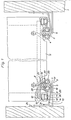
- a drawer 2 is mounted on two guides 3 extendable.
- the guide 3 consists of an outer rail 4 which is mounted on an inner rail 5 by means of balls 6.
- the outer rail 4 is designed as a hollow profile which is triangular in cross section and has a longitudinal slot 7 for the inner rail 5 to pass through.
- the connection between the outer rail 4 and the drawer 2 is made on the one hand by a carrier 8 and on the other hand via a support arm 9.
- This has a threaded sleeve 10 directed towards the drawer 2, in which an adjusting bolt 11 is stored.
- the support head 12 of the adjusting bolt 11 is supported in the bottom of a continuous bore 13, the outer diameter of the support head 12 corresponding to the outer diameter of the threaded sleeve 10, so that there is a relatively long guidance within the bore 13 without this having to be offset. No parts protrude below the support arm 9, so that a relatively narrow structure is possible.
- the inner rail 5 is composed of two U-shaped bent sheets 14 and 15. Each one of the strip-shaped legs 16 and 17 lie flat on one another and are connected to one another by spot welding. Their free ends 19 and 20 are bent outward by approximately 45 ° and form a running surface for the upper row of balls 21. The two lower rows of balls 22 and 23 lie directly on the strips 16 and 17 and an upward lift is provided by the bent edges 19 and 20 prevented. The pressure load by the upper row of balls 21 exerts forces which the strips 16 and 17 seek to push outwards, but this pressure is in turn absorbed by the two lower rows of balls 22 and 23.
- the outer bar 17 is attached to the opposite leg 24 on the wall of the furniture 1. Since the base area 25 is relatively long and, as a result, a large lever arm results, the base area 26 of the second plate 15 reinforces it, the opposite leg 27 with the Leg 24 of the other sheet is firmly connected.
- the G rundflä- surface 26 runs obliquely with respect to this base 25 so that a triangular arrangement.
- the balls 6 of the upper row of balls 21 and the two lower rows of balls 22 and 23 are each arranged in common cages 28.
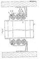
- Fig. 2 shows a triple extension, with three guides 28, 29 and 30 are arranged one above the other.
- the lowermost guide 28 is designed in exactly the same way as the guide 3 according to FIG. 1, but there is no direct attachment of the outer rail 4 to the drawer 2, but the inner rail 31 of the guide 29 arranged above it consists of two strips 32 and 33, which are on their lower End are bent apart, the two legs 34 and 35 adapted to the shape of the outer rail 4 and connected to it. Only the top guide 30 is then fastened to a fitting part 36 connected to the drawer 2 by means of screws 37.
Landscapes
- Drawers Of Furniture (AREA)
- Assembled Shelves (AREA)
- Details Of Garments (AREA)
- Casings For Electric Apparatus (AREA)
- Outer Garments And Coats (AREA)
- Fluid-Damping Devices (AREA)
- Glass Compositions (AREA)
- Compositions Of Macromolecular Compounds (AREA)
- Table Devices Or Equipment (AREA)
Abstract
Description
- Es sind bereits Auszugsführungen für Schubladen bekannt, bei denen die Außenschiene mittels in Käfigen gehaltener Kugeln auf einer Innenschiene verschiebbar gelagert ist. Die Außenschiene besteht dabei aus einem dreieckigen Hohlprofil mit Längsschlitz für den Durchtritt der Innenschiene. Bei dieser handelt es sich um eine Vollprofilschiene mit dreieckigem Querschnitt, wobei jeweils an den Ecken Kugellaufflächen angeformt sind. Die Herstellung einer derartigen Vollprofilschiene ist einerseits verhältnismäßig teuer und andererseits ergibt sich ein unnötig großer Materialaufwand.
- Die Aufgabe der vorliegenden Erfindung ist es, eine in ihrem Aufbau einfache, leicht und billig unter möglichst geringem Materialaufwand herzustellende Führung zu schaffen. Dies wird bei einer Führung der bekannten Art erfindungsgemäß dadurch erreicht, daß die Innenschiene aus zwei flach aneinanderliegenden Leisten besteht, deren in die Außenschiene hineinragenden Längskanten zur Bildung einer Kugellaufbahn nach außen abgewinkelt sind. Während die oberen Kugeln im abgewinkelten Teil der Leisten laufen, liegen die beiden unteren an den flach verlaufenden Teilen der Leisten an, wobei ein Abheben nach oben durch die abgewinkelten Kanten verhindert wird. Man erhält also durch den relativ einfachen Bearbeitungsvorgang des Abwinkelns von zwei Leisten die gewünschten drei Kugellaufbahnen. Durch die Gewichtsbelastung des auszuzziehenden Möbelteils ergeben sich durch die obere Kugelreihe auf die umgebogenen Kanten nach außen drückende Kräfte. Diese werden aber wiederum durch die beiden unteren Kugelreihen aufgehoben, so daß die beiden Leisten schon durch die gemeinsamen Montagemittel zusammengehalten werden. Um jedoch ein Auseinanderklaffen der beiden Leisten mit Sicherheit zu verhindern, sind diese zweckmäßig durch Punktschweißung miteinander verbunden.
- Zur Verbindung der Innenschiene mit dem entsprechenden Möbelteil kann, wie üblich, ein Winkelprofil verwendet werden, jedoch ergibt sich eine weitere Vereinfachung, wenn zumindest eine der Leisten an ihrem freien Ende verlängert und U-förmig zu einem Befestigungswinkel abgebogen wird. Ein solches Teil kann beispielsweise aus einer Blechtafel in einem Arbeitsgang hergestellt werden. Wenn der Hebelarm zwischen der Befestigungsstelle und der Innenschiene verhältnismäßig groß ist, besteht immer die Gefahr, daß bei größeren Belastungen des Möbelteils ein Absenken der Innenschiene erfolgt. Um diese zusätzlich abzustützen, kann nach einem weiteren Merkmal der Erfindung auch die zweite Leiste an ihrem freien Ende verlängert und in gleicher Richtung wie die erste so U-förmig abgebogen werden, daß die Winkelteile ineinander liegen. Wenn dann das innenliegende Winkelteil mit seiner Querfläche schräg zur Querfläche des anderen verläuft, ergibt sich eine dreieckförmige Ausbildung, welche ein Absinken der Innenschiene nahezu vollständig ausschließt.
- Wenn die erfindungsgemäße Führung für einen Mehrfachauszug verwendet werden soll, werden die freien Enden der Leisten der Innenseite der Außenform der Außenschiene angepaßt, nach außen abgewinkelt und auf eine darunterliegende Außenschiene aufgesetzt, so daß sich zwei, drei oder noch mehr Führungen übereinander ergeben.
- Als Außenschiene wird zweckmäßig ein dreieckförmiges Hohlprofil mit Durchtrittsschlitz für die Befestigung der Innenschiene gewählt. Dieses wird mittels eines Tragarmes mit einem Möbelteil verbunden. Der Tragarm weist dabei vorzugsweise an seinem Abstützende eine zum Möbelteil gerichtete Gewindehülse mit Verstellbolzen auf, wobei der am Bolzen vorgesehene Stützkopf im Durchmesser dem Außendurchmesser der Gewindehülse entspricht. Eine solche Anordnung hat den Vorteil, daß im Möbelteil eine durchgehende Bohrung angeordnet werden kann. Da keinerlei Teile nach unten herausragen, kann die gesamte Anordnung noch kompakter aufgebaut werden.
- Die Zeichnung zeigt Ausführungsbeispiele der Erfindung. Es stellen dar:
- Fig. 1 die abgebrochene, teilweise geschnittene Vorderansicht eines Möbelteils mit ausziehbarer Schublade auf einfacher Führung,
- Fig. 2 eine Darstellung nach Fig. 1 mit dreifacher Führung.
- In dem Möbelteil 1 ist eine Schublade 2 auf zwei Führungen 3 ausziehbar gelagert. Die Führung 3 besteht dabei aus einer Außenschiene 4, die auf einer Innenschiene 5 mittels Kugeln,6 gelagert ist.
- Die Außenschiene 4 ist als im Querschnitt dreieckförmiges Hohlprofil ausgebildet und weist einen Längsschlitz 7 zum Durchtritt der Innenschiene 5 auf. Die Verbindung zwischen der Außenschiene 4 und der Schublade 2 erfolgt einerseits durch einen Träger 8 und andererseits über einen Tragarm 9. Dieser weist eine zur Schublade 2 hin gerichtete Gewindehülse 10 auf, in der ein Stellbolzen 11 gelagert ist. Der Stützkopf 12 des Stellbolzens 11 stützt sich im Grund einer durchgehenden Bohrung 13 ab, wobei der Außendurchmesser des Stützkopfes 12 dem Außendurchmesser der Gewindehülse 10 entspricht, so daß sich eine verhältnismäßig lange Führung innerhalb der Bohrung 13 ergibt, ohne daß diese abgesetzt zu sein braucht. Unterhalb des Tragarmes 9 stehen keinerlei Teile vor, so daß ein verhältnismäßig enger Aufbau möglich ist.
- Die Innenschiene 5 setzt sich aus zwei U-förmig abgebogenen Blechen 14 und 15 zusammen. Jeweils die einen leistenförmigen Schenkel 16 und 17 liegen flach aufeinander und sind durch Punktschweißung miteinander verbunden. Ihre freien Enden 19 und 20 sind etwa um 45° nach außen abgebogen und bilden eine Lauffläche für die obere Kugelreihe 21. Die beiden unteren Kugelreihen 22 und 23 liegen unmittelbar an den Leisten 16 und 17 an und ein Abheben nach oben wird durch die umgebogenen Kanten 19 und 20 verhindert. Die Druckbelastung durch die obere Kugelreihe 21 übt zwar Kräfte aus, welche die Leisten 16 und 17 nach außen zu drükken suchen, jedoch wird dieser Druck durch die beiden unteren Kugelreihen 22 und 23 wiederum aufgenommen.
- Die außenliegende Leiste 17 ist mit dem entgegengesetzten Schenkel 24 an der Wand des Möbels 1 befestigt. Da die Grundfläche 25 verhältnismäßig lang ist und sich infolgedessen ein großer Hebelarm ergibt, erfolgt eine Verstärkung durch die Grundfläche 26 des zweiten Blechs 15, wobei der gegenüberliegende Schenkel 27 mit dem Schenkel 24 des anderen Blechs fest verbunden ist. Die Grundflä- che 26 läuft dabei schräg zur Grundfläche 25, so daß sich eine dreieckförmige Anordnung ergibt. Die Kugeln 6 der oberen Kugelreihe 21 und der beiden unteren Kugelreihen 22 und 23 sind jeweils in gemeinsamen Käfigen 28 angeordnet.
- Fig. 2 zeigt einen Dreifachauszug, wobei drei Führungen 28, 29 und 30 übereinander angeordnet sind. Die unterste Führung 28 ist genauso wie die Führung 3 nach Fig. 1 ausgebildet, jedoch erfolgt keine unmittelbare Befestigung der Außenschiene 4 an der Schublade 2, sondern die Innenschiene 31 der darüber angeordneten Führung 29 besteht aus zwei Leisten 32 und 33, die an ihrem unteren Ende auseinandergebogen sind, wobei die beiden Schenkel 34 und 35 der Form der Außenschiene 4 angepaßt und mit dieser verbunden sind. Erst die oberste Führung 30 ist dann an einem mit der Schublade 2 verbundenen Beschlagteil 36 mittels Schrauben 37 befestigt.
Claims (7)
Priority Applications (1)
| Application Number | Priority Date | Filing Date | Title |
|---|---|---|---|
| AT85102687T ATE30834T1 (de) | 1984-04-17 | 1985-03-09 | Fuehrung, insbesondere fuer auskippbare moebelteile. |
Applications Claiming Priority (2)
| Application Number | Priority Date | Filing Date | Title |
|---|---|---|---|
| DE3414405 | 1984-04-17 | ||
| DE19843414405 DE3414405A1 (de) | 1984-04-17 | 1984-04-17 | Fuehrung, insbesondere fuer auskippbare moebelteile |
Publications (3)
| Publication Number | Publication Date |
|---|---|
| EP0158811A2 true EP0158811A2 (de) | 1985-10-23 |
| EP0158811A3 EP0158811A3 (en) | 1985-12-18 |
| EP0158811B1 EP0158811B1 (de) | 1987-11-19 |
Family
ID=6233763
Family Applications (1)
| Application Number | Title | Priority Date | Filing Date |
|---|---|---|---|
| EP85102687A Expired EP0158811B1 (de) | 1984-04-17 | 1985-03-09 | Führung, insbesondere für auskippbare Möbelteile |
Country Status (8)
| Country | Link |
|---|---|
| US (1) | US4606588A (de) |
| EP (1) | EP0158811B1 (de) |
| JP (1) | JPS61309A (de) |
| AT (1) | ATE30834T1 (de) |
| AU (1) | AU573494B2 (de) |
| CA (1) | CA1235451A (de) |
| DE (1) | DE3414405A1 (de) |
| ES (1) | ES286030Y (de) |
Cited By (7)
| Publication number | Priority date | Publication date | Assignee | Title |
|---|---|---|---|---|
| EP0226389A3 (en) * | 1985-12-04 | 1988-06-01 | Paul Adrian Southon Jackson | A ball slide system |
| GB2197184B (en) * | 1986-11-14 | 1990-08-22 | King Otto Gmbh | Arrangement in a cabinet |
| DE4114708A1 (de) * | 1991-05-06 | 1992-11-12 | Lautenschlaeger Mepla Werke | Befestigungseinrichtung fuer laufschienen von schubladen-ausziehfuehrungen |
| WO2012007400A1 (de) * | 2010-07-15 | 2012-01-19 | Paul Hettich Gmbh & Co. Kg | Auszugsführung für möbel und verfahren zur herstellung einer auszugsführung |
| AT508265B1 (de) * | 2009-06-10 | 2013-05-15 | Blum Gmbh Julius | Ausziehführung für schubladen |
| EP2745738A4 (de) * | 2011-08-18 | 2015-04-01 | Segos Co Ltd | Schiene |
| WO2015117731A1 (de) * | 2014-02-07 | 2015-08-13 | Kesseböhmer Holding e.K. | Schrankauszug |
Families Citing this family (23)
| Publication number | Priority date | Publication date | Assignee | Title |
|---|---|---|---|---|
| DE3623743A1 (de) * | 1986-07-14 | 1988-01-21 | Lautenschlaeger Kg Karl | Ausziehfuehrung |
| DE3702238A1 (de) * | 1987-01-27 | 1988-08-04 | Lautenschlaeger Kg Karl | Ausziehfuehrung |
| US5549377A (en) * | 1995-06-08 | 1996-08-27 | Snap-On Technologies, Inc. | Corrugated three-piece drawer slide assembly |
| US5992956A (en) * | 1998-02-27 | 1999-11-30 | Snap-On Tools Company | Inclined slide assemblies for vertical drawers |
| DE29807540U1 (de) * | 1998-04-29 | 1998-06-10 | Paul Hettich Gmbh & Co., 32278 Kirchlengern | Schubkastenauszugführung |
| US6027193A (en) * | 1999-02-26 | 2000-02-22 | Grass America, Inc. | Two-part undermount drawer guide assembly with pivot member |
| US6135584A (en) * | 1999-03-05 | 2000-10-24 | Snap-On Tools Company | Vertical drawer with catch basin and storage chest containing same |
| US6481812B1 (en) | 2000-09-19 | 2002-11-19 | Grass America, Inc. | Undermount drawer guide assembly |
| DE10135161B4 (de) * | 2001-07-19 | 2005-06-30 | Accuride International Gmbh | Kugelgelagerte Teleskopschiene |
| US7434362B2 (en) * | 2001-07-20 | 2008-10-14 | Unirac, Inc. | System for removably and adjustably mounting a device on a surface |
| MY131063A (en) * | 2002-05-17 | 2007-07-31 | Harn Marketing Sdn Bhd | Guide rails pull-out drawer/equipment |
| DE10244911A1 (de) * | 2002-09-25 | 2004-04-08 | Peter Prof. Dipl.-Wirtsch.-Ing. Dr.-Ing. Groche | Führungs-Profilteil |
| US7600349B2 (en) | 2003-02-26 | 2009-10-13 | Unirac, Inc. | Low profile mounting system |
| US20070256681A1 (en) * | 2006-05-03 | 2007-11-08 | Chi-Hsiung Chiang | Smoke exhauster mounting structure |
| GB0616733D0 (en) * | 2006-08-23 | 2006-10-04 | Accuride Int Ltd | A sliding support assembly |
| KR101000744B1 (ko) * | 2007-11-05 | 2010-12-14 | 박윤식 | 하부장착형 슬라이드 및 그 제조방법 |
| JP5239332B2 (ja) * | 2007-12-27 | 2013-07-17 | アイシン精機株式会社 | 車両用シートスライド装置 |
| US20110249921A1 (en) * | 2010-04-09 | 2011-10-13 | Huang Kuo-Sheng | Hidden type sliding rail structure |
| DE102013204547B4 (de) | 2013-03-15 | 2025-07-24 | Faurecia Innenraum Systeme Gmbh | Montageanordnung eines Handschuhfachs |
| US10279954B2 (en) * | 2013-11-21 | 2019-05-07 | Bradford Company | Container having tracks with rounded edges to facilitate movement of dunnage supports |
| US9731863B2 (en) | 2013-11-21 | 2017-08-15 | Bradford Company | Container having multiple levels of slots to facilitate movement of dunnage |
| CN105508422A (zh) * | 2016-01-27 | 2016-04-20 | 无锡海达尔精密滑轨股份有限公司 | 三排滚珠滑轨 |
| DE102016225807A1 (de) * | 2016-12-21 | 2018-06-21 | BSH Hausgeräte GmbH | Haushaltsgeschirrspülmaschine |
Family Cites Families (10)
| Publication number | Priority date | Publication date | Assignee | Title |
|---|---|---|---|---|
| BE443576A (de) * | ||||
| GB164119A (en) * | 1920-03-02 | 1921-06-02 | Everett Stuck | Improvements in or relating to means or devices for supporting drawers, shelves and other sliding structures |
| GB669664A (en) * | 1949-08-23 | 1952-04-09 | Cox & Co Watford Ltd | Improvements in slides for vehicle seats and the like |
| US2780501A (en) * | 1952-02-09 | 1957-02-05 | Ainsworth Mfg Corp | Seat slide |
| US3205025A (en) * | 1963-02-08 | 1965-09-07 | Standard Prec | Drawer slide |
| US3272583A (en) * | 1964-12-21 | 1966-09-13 | Edward P Averdieck | Sliding adjustable drawer |
| JPS51120861A (en) * | 1975-04-12 | 1976-10-22 | Tookai Sukuriin Kk | Device for suspending filing cabinet or the like |
| JPS5917130Y2 (ja) * | 1977-07-09 | 1984-05-19 | 株式会社クボタ | 苗植付装置 |
| DE3127701A1 (de) * | 1981-07-14 | 1983-02-10 | Karl Lautenschläger KG, Möbelbeschlagfabrik, 6107 Reinheim | "kugel-ausziehfuehrung" |
| DE3323195A1 (de) * | 1983-06-28 | 1985-01-03 | Wilhelm Pöttker u. Co, 4780 Lippstadt | Kugelgelagerte schubfuehrung fuer schubkaesten oder tablarboeden |
-
1984
- 1984-04-17 DE DE19843414405 patent/DE3414405A1/de not_active Withdrawn
-
1985
- 1985-03-09 EP EP85102687A patent/EP0158811B1/de not_active Expired
- 1985-03-09 AT AT85102687T patent/ATE30834T1/de not_active IP Right Cessation
- 1985-03-28 AU AU40474/85A patent/AU573494B2/en not_active Ceased
- 1985-04-08 US US06/720,810 patent/US4606588A/en not_active Expired - Fee Related
- 1985-04-15 ES ES1985286030U patent/ES286030Y/es not_active Expired
- 1985-04-16 CA CA000479235A patent/CA1235451A/en not_active Expired
- 1985-04-17 JP JP60080445A patent/JPS61309A/ja active Pending
Cited By (11)
| Publication number | Priority date | Publication date | Assignee | Title |
|---|---|---|---|---|
| EP0226389A3 (en) * | 1985-12-04 | 1988-06-01 | Paul Adrian Southon Jackson | A ball slide system |
| GB2197184B (en) * | 1986-11-14 | 1990-08-22 | King Otto Gmbh | Arrangement in a cabinet |
| DE4114708A1 (de) * | 1991-05-06 | 1992-11-12 | Lautenschlaeger Mepla Werke | Befestigungseinrichtung fuer laufschienen von schubladen-ausziehfuehrungen |
| DE4114708C2 (de) * | 1991-05-06 | 2000-11-30 | Lautenschlaeger Mepla Werke | Befestigungseinrichtung für Laufschienen von Schubladen-Ausziehführungen |
| AT508265B1 (de) * | 2009-06-10 | 2013-05-15 | Blum Gmbh Julius | Ausziehführung für schubladen |
| US8777340B2 (en) | 2009-06-10 | 2014-07-15 | Julius Blum Gmbh | Pull-out guide for drawers |
| WO2012007400A1 (de) * | 2010-07-15 | 2012-01-19 | Paul Hettich Gmbh & Co. Kg | Auszugsführung für möbel und verfahren zur herstellung einer auszugsführung |
| CN103002769A (zh) * | 2010-07-15 | 2013-03-27 | 保罗海蒂诗有限及两合公司 | 用于家具的抽拉引导装置和用来制造抽拉引导装置的方法 |
| EP2745738A4 (de) * | 2011-08-18 | 2015-04-01 | Segos Co Ltd | Schiene |
| WO2015117731A1 (de) * | 2014-02-07 | 2015-08-13 | Kesseböhmer Holding e.K. | Schrankauszug |
| CN105979819A (zh) * | 2014-02-07 | 2016-09-28 | 克塞伯默尔控股两合公司 | 柜抽拉装置 |
Also Published As
| Publication number | Publication date |
|---|---|
| CA1235451A (en) | 1988-04-19 |
| US4606588A (en) | 1986-08-19 |
| ATE30834T1 (de) | 1987-12-15 |
| EP0158811B1 (de) | 1987-11-19 |
| ES286030U (es) | 1985-11-01 |
| DE3414405A1 (de) | 1985-10-17 |
| EP0158811A3 (en) | 1985-12-18 |
| ES286030Y (es) | 1986-06-01 |
| AU573494B2 (en) | 1988-06-09 |
| AU4047485A (en) | 1985-10-24 |
| JPS61309A (ja) | 1986-01-06 |
Similar Documents
| Publication | Publication Date | Title |
|---|---|---|
| EP0158811B1 (de) | Führung, insbesondere für auskippbare Möbelteile | |
| AT401460B (de) | Befestigungseinrichtung für laufschienen von schubladen-ausziehführungen | |
| AT392204B (de) | Regal | |
| DE3641325A1 (de) | Distanzstueck fuer schubladen-ausziehfuehrungen | |
| DE10135161B4 (de) | Kugelgelagerte Teleskopschiene | |
| DE3442407C2 (de) | ||
| DE10150707C1 (de) | Vorrichtung zur Aufnahme eines Lauforgans | |
| DE3323195A1 (de) | Kugelgelagerte schubfuehrung fuer schubkaesten oder tablarboeden | |
| DE3033360C2 (de) | ||
| DE3106103A1 (de) | Traeger fuer regalboeden, insbesondere fuer den ladenbau | |
| AT413186B (de) | Unterbodenausziehführung für ausziehbare möbelteile | |
| DE2923903A1 (de) | Wandbefestigungselement fuer plattenheizkoerper | |
| DE19822349A1 (de) | Ausziehvorrichtung für Hochschränke | |
| AT312850B (de) | Auszug mit Abrollkörpern, vorzugsweise mit Laufrollen, für ausziehbare Möhbelteile | |
| CH543259A (de) | Möbel oder Gestell mit einem ausziehbaren Teil | |
| EP0055861A1 (de) | Befestigungselement für Möbel | |
| DE3604443A1 (de) | Kabinen fuer sanitaer- oder umkleideraeume | |
| DE2166276C3 (de) | Verstellbeschlag zur einstellbaren Befestigung der Frontplatte eines ausziehbaren Möbelteiles | |
| DE3830212C2 (de) | ||
| AT405121B (de) | Ausziehvorrichtung für hochschränke | |
| DE29809614U1 (de) | Ausziehvorrichtung in Differentialbauart für Hochschränke | |
| DE7906753U1 (de) | Befestigungsvorrichtung | |
| DE29923593U1 (de) | Rollen-Ausziehführung | |
| DE3535423C2 (de) | Beschlag für eine in der Höhe und in der Neigung einstellbare Platte eines Arbeitstisches oder dergleichen | |
| DE29701559U1 (de) | Tischgestell, insbesondere für einen Bürotisch |
Legal Events
| Date | Code | Title | Description |
|---|---|---|---|
| PUAI | Public reference made under article 153(3) epc to a published international application that has entered the european phase |
Free format text: ORIGINAL CODE: 0009012 |
|
| PUAL | Search report despatched |
Free format text: ORIGINAL CODE: 0009013 |
|
| AK | Designated contracting states |
Designated state(s): AT FR GB IT NL |
|
| AK | Designated contracting states |
Designated state(s): AT FR GB IT NL |
|
| 17P | Request for examination filed |
Effective date: 19851113 |
|
| 17Q | First examination report despatched |
Effective date: 19870324 |
|
| GRAA | (expected) grant |
Free format text: ORIGINAL CODE: 0009210 |
|
| AK | Designated contracting states |
Kind code of ref document: B1 Designated state(s): AT FR GB IT NL |
|
| PG25 | Lapsed in a contracting state [announced via postgrant information from national office to epo] |
Ref country code: NL Effective date: 19871119 Ref country code: IT Free format text: LAPSE BECAUSE OF FAILURE TO SUBMIT A TRANSLATION OF THE DESCRIPTION OR TO PAY THE FEE WITHIN THE PRESCRIBED TIME-LIMIT;WARNING: LAPSES OF ITALIAN PATENTS WITH EFFECTIVE DATE BEFORE 2007 MAY HAVE OCCURRED AT ANY TIME BEFORE 2007. THE CORRECT EFFECTIVE DATE MAY BE DIFFERENT FROM THE ONE RECORDED. Effective date: 19871119 |
|
| REF | Corresponds to: |
Ref document number: 30834 Country of ref document: AT Date of ref document: 19871215 Kind code of ref document: T |
|
| ET | Fr: translation filed | ||
| GBT | Gb: translation of ep patent filed (gb section 77(6)(a)/1977) | ||
| NLV1 | Nl: lapsed or annulled due to failure to fulfill the requirements of art. 29p and 29m of the patents act | ||
| PLBE | No opposition filed within time limit |
Free format text: ORIGINAL CODE: 0009261 |
|
| STAA | Information on the status of an ep patent application or granted ep patent |
Free format text: STATUS: NO OPPOSITION FILED WITHIN TIME LIMIT |
|
| 26N | No opposition filed | ||
| PGFP | Annual fee paid to national office [announced via postgrant information from national office to epo] |
Ref country code: FR Payment date: 19890114 Year of fee payment: 5 |
|
| PGFP | Annual fee paid to national office [announced via postgrant information from national office to epo] |
Ref country code: AT Payment date: 19890216 Year of fee payment: 5 |
|
| PGFP | Annual fee paid to national office [announced via postgrant information from national office to epo] |
Ref country code: GB Payment date: 19890228 Year of fee payment: 5 |
|
| PG25 | Lapsed in a contracting state [announced via postgrant information from national office to epo] |
Ref country code: GB Effective date: 19900309 Ref country code: AT Effective date: 19900309 |
|
| GBPC | Gb: european patent ceased through non-payment of renewal fee | ||
| PG25 | Lapsed in a contracting state [announced via postgrant information from national office to epo] |
Ref country code: FR Effective date: 19901130 |
|
| REG | Reference to a national code |
Ref country code: FR Ref legal event code: ST |