EP0158812A1 - Croisillon de barres de contrôle pour un assemblage du combustible nucléaire - Google Patents
Croisillon de barres de contrôle pour un assemblage du combustible nucléaire Download PDFInfo
- Publication number
- EP0158812A1 EP0158812A1 EP85102690A EP85102690A EP0158812A1 EP 0158812 A1 EP0158812 A1 EP 0158812A1 EP 85102690 A EP85102690 A EP 85102690A EP 85102690 A EP85102690 A EP 85102690A EP 0158812 A1 EP0158812 A1 EP 0158812A1
- Authority
- EP
- European Patent Office
- Prior art keywords
- vanes
- bar
- fingers
- hub
- spider assembly
- Prior art date
- Legal status (The legal status is an assumption and is not a legal conclusion. Google has not performed a legal analysis and makes no representation as to the accuracy of the status listed.)
- Granted
Links
Images


Classifications
-
- G—PHYSICS
- G21—NUCLEAR PHYSICS; NUCLEAR ENGINEERING
- G21C—NUCLEAR REACTORS
- G21C7/00—Control of nuclear reaction
- G21C7/06—Control of nuclear reaction by application of neutron-absorbing material, i.e. material with absorption cross-section very much in excess of reflection cross-section
- G21C7/08—Control of nuclear reaction by application of neutron-absorbing material, i.e. material with absorption cross-section very much in excess of reflection cross-section by displacement of solid control elements, e.g. control rods
- G21C7/10—Construction of control elements
-
- G—PHYSICS
- G21—NUCLEAR PHYSICS; NUCLEAR ENGINEERING
- G21C—NUCLEAR REACTORS
- G21C7/00—Control of nuclear reaction
- G21C7/06—Control of nuclear reaction by application of neutron-absorbing material, i.e. material with absorption cross-section very much in excess of reflection cross-section
- G21C7/08—Control of nuclear reaction by application of neutron-absorbing material, i.e. material with absorption cross-section very much in excess of reflection cross-section by displacement of solid control elements, e.g. control rods
- G21C7/10—Construction of control elements
- G21C7/117—Clusters of control rods; Spider construction
-
- Y—GENERAL TAGGING OF NEW TECHNOLOGICAL DEVELOPMENTS; GENERAL TAGGING OF CROSS-SECTIONAL TECHNOLOGIES SPANNING OVER SEVERAL SECTIONS OF THE IPC; TECHNICAL SUBJECTS COVERED BY FORMER USPC CROSS-REFERENCE ART COLLECTIONS [XRACs] AND DIGESTS
- Y02—TECHNOLOGIES OR APPLICATIONS FOR MITIGATION OR ADAPTATION AGAINST CLIMATE CHANGE
- Y02E—REDUCTION OF GREENHOUSE GAS [GHG] EMISSIONS, RELATED TO ENERGY GENERATION, TRANSMISSION OR DISTRIBUTION
- Y02E30/00—Energy generation of nuclear origin
- Y02E30/30—Nuclear fission reactors
Definitions
- the present invention relates generally to nuclear reactors and, more particularly, to an improved spider assembly for supporting an array of control rods, especially water displacer rods, for vertical movement within a reactor.
- the core portion comprises a large number of elongate fuel elements or rods. grouped in and supported by frameworks referred to as fuel assemblies.
- the fuel assemblies are generally elongate and receive support and alignment from upper and lower transversely extending core support plates.
- Conventional designs of these fuel assemblies include a plurality of fuel rods and hollow control-rod guide thimbles held in an organized array by grids spaced along the fuel assembly length and attached to the guide thimbles. Top and bottom nozzles on opposite ends thereof are secured to the guide thimbles, thereby forming an integral fuel assembly.
- a fluid coolant such as water, is directed upwardly through apertures in the lower core support plate and along the various fuel assemblies to receive the thermal energy therefrom.
- control rods which are moved into and out of the core region and generally comprise a material having a high neutron absorption cross-section, such as boron carbide, tantalum, a combination of silver-indium and cadmium, or the like, as well known in the art.
- Each vane has a configuration similar to that of a pennant so as to provide it with an inner end or edge long enough, in the axial direction of the hub, to permit the vane to be affixed to the hub.
- Cylindrical control-rod connecting fingers are mounted on the vanes, some of the vanes having one connecting finger associated therewith and others two. The fingers closest to the central hub are at a higher elevation than those more distant therefrom, due to the use of the pennant-shaped vanes and to mounting the vanes at different axial height locations on the central hub.
- the inner fingers which extend higher exist in aligning the spider assembly as it is raised up into the upper internals of the reactor.
- the vanes and the fingers are manufactured as separate components and then welded together to form a vane-finger sub-unit.
- the vane-finger sub-units are then welded to the central hub so as to form an integral unit.
- each of the welds must be inspected to ensure that it is a good or sound weld capable of sustaining the load of the control rods as well as the various moment forces generated during a stepping activity.
- Another method of controlling core reactivity is by changing the water (moderator) inventory of the core for the purpose of varying the neutron energy spectrum and fuel utilization (moderator control system).
- moderator control system As well known in the art, there are several ways of changing the water inventory, one of which is to plug the opposite ends of hollow guide thimbles of a fuel assembly; however, a more common approach is to use water displacer rods which are inserted in the guide thimbles, thereby to displace the water therein and thus change the volume of water in the associated fuel assembly to moderate the reactivity of the fuel.
- the rods associated with any given fuel assembly are supported at their upper ends, in a fixed array, from a spider assembly on the top nozzle of the fuel assembly.
- spider assemblies for water displacer rods unlike spider assemblies for regular control rods, ordinarily are not structurally designed to be moved on a more constant basis and to withstand the load and moment forces resulting from such movements or stepping actions.
- the invention accordingly resides in a spider assembly for supporting control rods for vertical movement thereof in a nuclear reactor having a plurality of fuel assemblies disposed therein in closely spaced relationship with respect to each other, said spider assembly including a hub having thereon radial vanes with fingers for connection to the control rods, characterized in that said radial vanes comprise a group of straight vanes having some of said fingers disposed thereon, and a group of T-bar vanes including T-bars which have the remaining fingers disposed thereon, the arrangement being such that the straight vanes have the fingers thereon located for connection to control rods in one fuel assembly having the spider assembly associated therewith, and the T-bar vanes have some of the fingers thereon located for connection to other control rods in said one fuel assembly and have the remaining fingers thereon located for connection to control rods in fuel assemblies adjacent to said one fuel assembly.
- each of the straight and T-bar vanes, together with the respective fingers thereon is of a monolithic one-piece construction forming a jointless sub-unit secured to the hub.
- the currently preferred manner of manufacturing T-bar vanes of monolithic construction is by casting, whereas the straight vanes lend themselves both to casting and to being formed, such as swaged, from a suitable piece of stock, the latter method being preferred because of the lower cost and time factor involved.
- the vanes of each group i.e. the straight vanes of one group and the T-bar vanes of the other group, are spaced apart 90 degrees, and the straight vanes and the T-bar vanes are circumferentially spaced about the hub in alternating sequence with respect to one another.
- each of the straight and T-bar vanes preferably is of substantially constant axial height rather than pennant-shaped, and all of the vanes are mounted on the central hub at substantially the same axial height location which latter feature also simplifies the fabrication of the spider assembly while still enabling the inner fingers on the vanes to be extended beyond and above the outer fingers for the purpose of facilitating the alignment of the spider assembly with the upper internals of the reactor.
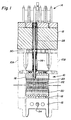
- FIG. 1 there is shown an overall combination (interface) of fuel assemblies (the middle one being generally designed with numeral 10 and the others, shown in phase form, being indicated at 10A and 10B), an upper core support plate 12 disposed above and extending across the tops of the fuel assemblies and a spider assembly 14 embodying the invention and generally designated by the numeral 14.
- the fuel assemblies 10, 10A and 10B are identical. Describing the assembly 10 as representative of all, it basically comprises a lower end structure or bottom nozzle 16 for supporting the assembly on the lower core plate (not shown) in the core region of a reactor; a number of guide tubes or thimbles 18 projecting longitudinally upward from the bottom nozzle 16; a plurality of transverse grids 20 axially spaced along the guide thimbles 18; an organized array of elongate fuel rods 22 transversely spaced and supported by the grids 20; an instrument tube 24 located in the center of the assembly; and an upper end structure or top nozzle 26 attached to the upper ends of the guide thimbles 18 to form therewith an integral assembly capable of being conventionally handled without damaging the assembly components.
- the fuel assemblies, such as assembly 10 do not form part of the invention propeor and, therefore need not be described herein in greater detail.
- the upper core support plate 12 being conven - tional, extends across the top of the fuel assembly 10 as well as across the top of other fuel assemblies, such as IOA, 10B, arranged within the core.
- the core plate 12 has a multiplicity of flow openings or passages 28 (only one of which is shown in Figure 1) which allow coolant to pass upwardly through the core. At least some of these openings or passages are axially aligned with guide thimbles 18 so as to enable water displacer rods 30 to be inserted down through the core plate passage and into the respective guide thimbles of the fuel assemblies 10, 10A and 10B.
- the spider assembly 14 Connected to the upper ends of the displacer rods 30 is the spider assembly 14 which supports the rods for vertical movement within the guide thimbles 18 effected by means of a conventional drive mechanism (not shown). It should be noted that although the spider assembly is shown in Figure 1 as disposed above the core plate 12 upon which it will rest when the displacer rods 30 are fully inserted in the guide thimbles 18, there are other arrangements with which the spider assembly 14 embodying the invention could be used and in which it would be located between the bottom of the core plate and the top of the fuel assembly.
- the spider assembly 14 basically comprises a central hub 32, a first group of vanes 34 radially extending outwardly from the hub 32 and including fingers 36 for connection to displacer rods, and a second group of vanes 38 which extend radially outward from the hub and have T-bars 40 with fingers 42 for connection to displacer rods.
- the fingers 36 on the first group of vanes 34 (hereinafter referred to as straight vanes) and the fingers 42 on the second group of vanes 38 (hereinafter referred to as T-bar vanes) are substantially identical.
- the fingers 36 of the straight vanes 34 are for connection to displacer rods associated with the fuel assembly 10
- some of the fingers 42 of the T-bar vanes 38 are for connection to displacer rods associated with fuel assembly 10 whilst others of the fingers 42 are for connection with displacer rods associated with adjacent fuel assemblies 10A, 10B, lOC and 10D.
- the central hub 32 is preferably in the form of an elongate cylindrical tube having an upper neck portion 44 ( Figure 3) which is internally threaded for connection thereof to the drive mechanism (not shown) utilized in the reactor for raising and lowering the spider assembly together with the displacer rods connected thereto.
- the hollow hub 32 is adapted to accommodate therein a conventional load absorbing mechanism (not shown) which comprises a coil spring held in a state of partial compression between the upper and lower ends of the hub, and serves to prevent shock loading as the spider assembly 14 is lowered onto the core plate.
- the tubular hub 32 has formed therein a plurality of elongate indentations or slots 46 spaced circumferentially about the hub and extending axially thereof.
- the slots 46 are all at the same axial height location and they do not extend completely through the wall of the tubular hub but communicate with the interior space of the latter each through a small hole 48.
- the straight vanes 34 there are four straight vanes 34 and four T-bar vanes 38 spaced circumferentially about the hub 32 in alternating sequence, the straight vanes 34 being angularly spaced substantially ninety degrees apart, and the T-bar vanes 38 being angularly spaced substantially ninety degrees apart.
- the T-bar vanes 38 are longer in the radial dimension than the straight vanes 34 so that the T-bar vanes extend beyond the outer boundaries of the fuel assembly (10) associated with the spider assembly, and into overlying relationship with fuel assemblies (10A, 10B, 10C and 10D) adjacent thereto.
- the straight vanes 34 overlie only the fuel assembly 10.
- Each T-bar vane 38 has two T-bars 40, namely, an outer T-bar positioned at the distal end of the vane, and an inner T-bar spaced between the outer T-bar and the hub 32.
- the outer T-bar of each T-bar vane 38 overlies an adjacent fuel assembly while the inner T-bar overlies the central fuel assembly i.e. the fuel assembly 10 associated with the spider assembly.
- the T-bars 40 of each T-bar vane 38 extend parallel to one another and perpendicular with respect to the longitudinal or radial axis of the T-bar vane.
- each straight vane 34 has two fingers 36, one of which (the outer finger) is located at the outer or distal end of the vane, and the other of which (the inner finger) is located between the outer finger and the hub 32.
- the vane portion between the outer and inner fingers and between the inner finger and the hub is in the form of a flat linear bar, whereas each finger is in the form of an elongate cylinder with its upper end dome-shaped.
- each finger 36 is greater than the transverse thickness of the vane portion between the inner and outer fingers, and the longitudinal axis of the inner and outer fingers 36 are parallel with respect to one another as well as to the longitudinal axis of the hub 32, the longitudinal axes of the inner and outer fingers of each vane lying in the same plane as the longitudinal axis of the hub.
- the vane portion between the inner and outer fingers of each straight vane 34 is rectangular, as is the vane portion between the inner finger and the hub except that it includes upper and lower tabs 52 and 54 respectively, formed thereon adjacent the inner end thereof.
- the rectangular vane portions of each vane rigidly interconnect the fingers thereof so as to maintain them securely in proper relationship with respect to one another and to the hub.
- the inner fingers project axially above the upper edges of the respective vanes to a greater height than the outer fingers. This feature facilitates a proper alignment of the spider assembly 14 with the upper internals of the reactor.
- each of the two T-bars 40 of each T-bar vane 38 has two fingers 42 which are on the terminal ends of the respective T-bar.
- the T-bar vanes 38 are similar to the straight vanes 34 insofar as their fingers 42 are as elongate cylinders with parallel axes; the T-bars and the radial vane portions are linear and of rectangular shape; there are upper and lower tabs 52 and 54 on the inner ends of each vane 38; and the fingers 42 on the inner T-bars 40 extend axially to a height greater than the axial height of the fingers 42 on the outer T-bars.
- the overall relationship is such that the fingers 42 on the inner T-bars 40 are at the same axial height or level as inner fingers 36 of the straight vanes 34.
- each of the straight vanes 34 _together with its fingers 36, and each of the T-bar vanes 38 together with its T-bars 40 and fingers 42, is formed as a sub-unit of monolithic, jointless one-piece construction.
- the preferred method of thus manufacturing the T-bar vanes or sub-units 38 is by casting, whereas the preferred method of manufacturing the straight vanes or sub-units 34 is by machining, e.g. swaging, a bar stock to conform to the desired configurations shown, although the straight vanes or sub-units can also be formed by casting, if desired. It is believed that such a monolithic one-piece construction is superior in strength, and in its ability to withstand moment forces such as result from stepping actions, to a composite construction formed from individual components welded together.
- each of the sub-units 34 and 38 has an integral extension 50 formed on the inner end thereof, which extension 50 is dimensioned to fit tightly into the associated slot 46 of the hub 32 so that, when inserted therein, the sub-unit will be firmly and properly positioned on the hub and ready to be joined thereto in a suitable manner, e.g. by brazing.
- the slots 46 do not extend completely through the wall of the tubular hub, so as not to unnecessarily weaken, but there are the small holes 48 which will enable the gases generated- during brazing to escape into and through the hollow of the hub 32.
Landscapes
- Physics & Mathematics (AREA)
- Engineering & Computer Science (AREA)
- Chemical & Material Sciences (AREA)
- Chemical Kinetics & Catalysis (AREA)
- Plasma & Fusion (AREA)
- General Engineering & Computer Science (AREA)
- High Energy & Nuclear Physics (AREA)
- Monitoring And Testing Of Nuclear Reactors (AREA)
- Molds, Cores, And Manufacturing Methods Thereof (AREA)
- Filling Or Discharging Of Gas Storage Vessels (AREA)
Applications Claiming Priority (2)
| Application Number | Priority Date | Filing Date | Title |
|---|---|---|---|
| US59515484A | 1984-03-30 | 1984-03-30 | |
| US595154 | 1990-10-10 |
Publications (2)
| Publication Number | Publication Date |
|---|---|
| EP0158812A1 true EP0158812A1 (fr) | 1985-10-23 |
| EP0158812B1 EP0158812B1 (fr) | 1988-08-17 |
Family
ID=24381964
Family Applications (1)
| Application Number | Title | Priority Date | Filing Date |
|---|---|---|---|
| EP85102690A Expired EP0158812B1 (fr) | 1984-03-30 | 1985-03-09 | Croisillon de barres de contrôle pour un assemblage du combustible nucléaire |
Country Status (5)
| Country | Link |
|---|---|
| EP (1) | EP0158812B1 (fr) |
| JP (1) | JPS60225089A (fr) |
| KR (1) | KR920007743B1 (fr) |
| DE (1) | DE3564507D1 (fr) |
| ES (1) | ES296613Y (fr) |
Cited By (7)
| Publication number | Priority date | Publication date | Assignee | Title |
|---|---|---|---|---|
| EP0225089A1 (fr) * | 1985-11-14 | 1987-06-10 | Westinghouse Electric Corporation | Arrangement pour le support des barres de réacteurs à eau, basé sur un alliage de zirconium résistant à l'usure |
| EP0225805A1 (fr) * | 1985-12-09 | 1987-06-16 | Westinghouse Electric Corporation | Croisillon de grappe de barres à ailes modifiées |
| US4855100A (en) * | 1988-03-02 | 1989-08-08 | Westinghouse Electric Corp. | Reconstitutable control rod spider assembly |
| US4993864A (en) * | 1988-12-15 | 1991-02-19 | Westinghouse Electric Corp. | Reconstitutable control assembly having removable control rods with detachable split upper end plugs |
| FR2742912A1 (fr) * | 1995-12-26 | 1997-06-27 | Framatome Sa | Grappe de commande pour reacteur nucleaire, a crayons demontables |
| WO2011157782A1 (fr) * | 2010-06-16 | 2011-12-22 | Commissariat à l'énergie atomique et aux énergies alternatives | Joint d'interface solide a porosite ouverte pour barre de commande nucleaire |
| US8582714B2 (en) | 2006-12-18 | 2013-11-12 | Areva Np | Fixed cluster having a spider-like support, corresponding pressurized water nuclear reactor core and assembly comprising a nuclear fuel assembly and such a fixed cluster |
Citations (4)
| Publication number | Priority date | Publication date | Assignee | Title |
|---|---|---|---|---|
| DE2248398A1 (de) * | 1971-10-11 | 1973-04-19 | Asea Atom Ab | Befestigungs- und arretierungsanordnung fuer fingersteuerstaebe in atomreaktoren |
| FR2168564A1 (fr) * | 1972-01-21 | 1973-08-31 | Westinghouse Electric Corp | |
| DE2406595A1 (de) * | 1973-02-20 | 1974-08-29 | Combustion Eng | Kernreaktor mit pufferung der steuerstaebe |
| EP0054787A2 (fr) * | 1980-12-16 | 1982-06-30 | Westinghouse Electric Corporation | Réacteur nucléaire commandé par dérive spectrale |
Family Cites Families (1)
| Publication number | Priority date | Publication date | Assignee | Title |
|---|---|---|---|---|
| ZA818402B (en) * | 1980-12-16 | 1982-11-24 | Westinghouse Electric Corp | Mechanical spectral shift reactor |
-
1985
- 1985-03-09 EP EP85102690A patent/EP0158812B1/fr not_active Expired
- 1985-03-09 DE DE8585102690T patent/DE3564507D1/de not_active Expired
- 1985-03-26 ES ES1985296613U patent/ES296613Y/es not_active Expired
- 1985-03-29 JP JP60064087A patent/JPS60225089A/ja active Pending
- 1985-03-30 KR KR1019850002164A patent/KR920007743B1/ko not_active Expired
Patent Citations (4)
| Publication number | Priority date | Publication date | Assignee | Title |
|---|---|---|---|---|
| DE2248398A1 (de) * | 1971-10-11 | 1973-04-19 | Asea Atom Ab | Befestigungs- und arretierungsanordnung fuer fingersteuerstaebe in atomreaktoren |
| FR2168564A1 (fr) * | 1972-01-21 | 1973-08-31 | Westinghouse Electric Corp | |
| DE2406595A1 (de) * | 1973-02-20 | 1974-08-29 | Combustion Eng | Kernreaktor mit pufferung der steuerstaebe |
| EP0054787A2 (fr) * | 1980-12-16 | 1982-06-30 | Westinghouse Electric Corporation | Réacteur nucléaire commandé par dérive spectrale |
Cited By (10)
| Publication number | Priority date | Publication date | Assignee | Title |
|---|---|---|---|---|
| EP0225089A1 (fr) * | 1985-11-14 | 1987-06-10 | Westinghouse Electric Corporation | Arrangement pour le support des barres de réacteurs à eau, basé sur un alliage de zirconium résistant à l'usure |
| EP0225805A1 (fr) * | 1985-12-09 | 1987-06-16 | Westinghouse Electric Corporation | Croisillon de grappe de barres à ailes modifiées |
| US4855100A (en) * | 1988-03-02 | 1989-08-08 | Westinghouse Electric Corp. | Reconstitutable control rod spider assembly |
| US4993864A (en) * | 1988-12-15 | 1991-02-19 | Westinghouse Electric Corp. | Reconstitutable control assembly having removable control rods with detachable split upper end plugs |
| FR2742912A1 (fr) * | 1995-12-26 | 1997-06-27 | Framatome Sa | Grappe de commande pour reacteur nucleaire, a crayons demontables |
| EP0782150A1 (fr) * | 1995-12-26 | 1997-07-02 | Framatome | Grappe de commande pour réacteur nucléaire, à crayons démontables |
| US5889832A (en) * | 1995-12-26 | 1999-03-30 | Framatome | Nuclear reactor control cluster having removable rods |
| US8582714B2 (en) | 2006-12-18 | 2013-11-12 | Areva Np | Fixed cluster having a spider-like support, corresponding pressurized water nuclear reactor core and assembly comprising a nuclear fuel assembly and such a fixed cluster |
| WO2011157782A1 (fr) * | 2010-06-16 | 2011-12-22 | Commissariat à l'énergie atomique et aux énergies alternatives | Joint d'interface solide a porosite ouverte pour barre de commande nucleaire |
| US9620251B2 (en) | 2010-06-16 | 2017-04-11 | Commissariat A L'energie Atomique Et Aux Energies Alternatives | Solid interface joint with open pores for nuclear control rod |
Also Published As
| Publication number | Publication date |
|---|---|
| ES296613U (es) | 1988-02-01 |
| EP0158812B1 (fr) | 1988-08-17 |
| ES296613Y (es) | 1988-11-01 |
| KR920007743B1 (ko) | 1992-09-16 |
| JPS60225089A (ja) | 1985-11-09 |
| KR850006633A (ko) | 1985-10-14 |
| DE3564507D1 (en) | 1988-09-22 |
Similar Documents
| Publication | Publication Date | Title |
|---|---|---|
| US5068083A (en) | Dashpot construction for a nuclear reactor rod guide thimble | |
| EP0311037B1 (fr) | Embout inférieur résistant aux débris pour assemblage de combustible nucléaire | |
| US4772447A (en) | Device for the spacing and holding in place of fuel rods in a fuel assembly | |
| EP0589312B1 (fr) | Embout inférieur pour assemblage de combustible nucléaire | |
| EP0146896B1 (fr) | Grille d'espacement partielle pour assemblage combustible d'un réacteur nucléaire | |
| US4820475A (en) | Burnable absorber rod push out attachment joint | |
| EP0159509B1 (fr) | Croisillon de barres de contrôle pour un assemblage du combustible nucléaire | |
| EP0158812A1 (fr) | Croisillon de barres de contrôle pour un assemblage du combustible nucléaire | |
| US4762676A (en) | Top nozzle adapter plate with fuel rod capture grid having pressure drop adjusting means | |
| US8582714B2 (en) | Fixed cluster having a spider-like support, corresponding pressurized water nuclear reactor core and assembly comprising a nuclear fuel assembly and such a fixed cluster | |
| US4683117A (en) | Nuclear fuel assembly incorporating primary and secondary structural support members | |
| EP0260601A2 (fr) | Grille d'espacement des aiguilles de combustible ayant des moyens de déflection pour le courant du réfrigérant liquide | |
| US4684501A (en) | Compliant inserts mounted in upper tie plate of BWR fuel assembly | |
| US4873051A (en) | Nuclear fuel grid outer strap | |
| EP0545587B1 (fr) | Assemblage combustible et grille d'espacement utilisant des barreaux de combustible fuselés | |
| US5859887A (en) | Nuclear fuel assembly support grid | |
| US4728487A (en) | Standardized reduced length burnable absorber rods for a nuclear reactor | |
| US5473649A (en) | Fuel element for a light-water nuclear reactor | |
| US5859886A (en) | Fuel assembly for a boiling water reactor | |
| US6389094B1 (en) | Integral forged shroud flange for a boiling water reactor | |
| US3945886A (en) | Control rod for nuclear reactor | |
| EP0526777B1 (fr) | Assemblage de combustible d'un réacteur à eau bouillante muni de tubes à eau | |
| EP0183069B1 (fr) | Barre de déplacement d'eau pour un réacteur nucléaire à dérive spectrale | |
| US4678618A (en) | Individual source positioning mechanism for a nuclear reactor fuel assembly | |
| US4687630A (en) | Top nozzle and guide thimble joint structure in a nuclear fuel assembly |
Legal Events
| Date | Code | Title | Description |
|---|---|---|---|
| PUAI | Public reference made under article 153(3) epc to a published international application that has entered the european phase |
Free format text: ORIGINAL CODE: 0009012 |
|
| AK | Designated contracting states |
Designated state(s): BE DE FR GB IT SE |
|
| 17P | Request for examination filed |
Effective date: 19860313 |
|
| 17Q | First examination report despatched |
Effective date: 19870514 |
|
| ITF | It: translation for a ep patent filed | ||
| GRAA | (expected) grant |
Free format text: ORIGINAL CODE: 0009210 |
|
| AK | Designated contracting states |
Kind code of ref document: B1 Designated state(s): BE DE FR GB IT SE |
|
| REF | Corresponds to: |
Ref document number: 3564507 Country of ref document: DE Date of ref document: 19880922 |
|
| ET | Fr: translation filed | ||
| ITTA | It: last paid annual fee | ||
| PLBE | No opposition filed within time limit |
Free format text: ORIGINAL CODE: 0009261 |
|
| STAA | Information on the status of an ep patent application or granted ep patent |
Free format text: STATUS: NO OPPOSITION FILED WITHIN TIME LIMIT |
|
| 26N | No opposition filed | ||
| PGFP | Annual fee paid to national office [announced via postgrant information from national office to epo] |
Ref country code: FR Payment date: 19901218 Year of fee payment: 7 |
|
| PGFP | Annual fee paid to national office [announced via postgrant information from national office to epo] |
Ref country code: SE Payment date: 19901227 Year of fee payment: 7 |
|
| PGFP | Annual fee paid to national office [announced via postgrant information from national office to epo] |
Ref country code: BE Payment date: 19910114 Year of fee payment: 7 |
|
| PGFP | Annual fee paid to national office [announced via postgrant information from national office to epo] |
Ref country code: DE Payment date: 19910330 Year of fee payment: 7 |
|
| PG25 | Lapsed in a contracting state [announced via postgrant information from national office to epo] |
Ref country code: SE Effective date: 19920310 |
|
| PG25 | Lapsed in a contracting state [announced via postgrant information from national office to epo] |
Ref country code: BE Effective date: 19920331 |
|
| BERE | Be: lapsed |
Owner name: WESTINGHOUSE ELECTRIC CORP. Effective date: 19920331 |
|
| PG25 | Lapsed in a contracting state [announced via postgrant information from national office to epo] |
Ref country code: FR Effective date: 19921130 |
|
| PG25 | Lapsed in a contracting state [announced via postgrant information from national office to epo] |
Ref country code: DE Effective date: 19921201 |
|
| REG | Reference to a national code |
Ref country code: FR Ref legal event code: ST |
|
| EUG | Se: european patent has lapsed |
Ref document number: 85102690.6 Effective date: 19921005 |
|
| REG | Reference to a national code |
Ref country code: GB Ref legal event code: IF02 |
|
| PGFP | Annual fee paid to national office [announced via postgrant information from national office to epo] |
Ref country code: GB Payment date: 20040119 Year of fee payment: 20 |
|
| PG25 | Lapsed in a contracting state [announced via postgrant information from national office to epo] |
Ref country code: GB Free format text: LAPSE BECAUSE OF EXPIRATION OF PROTECTION Effective date: 20050308 |
|
| REG | Reference to a national code |
Ref country code: GB Ref legal event code: PE20 |