EP0158978A2 - Montage de transducteurs dans un baffle, en particulier pour haut-parleurs, de préférence pour enceintes acoustiques - Google Patents
Montage de transducteurs dans un baffle, en particulier pour haut-parleurs, de préférence pour enceintes acoustiques Download PDFInfo
- Publication number
- EP0158978A2 EP0158978A2 EP85104406A EP85104406A EP0158978A2 EP 0158978 A2 EP0158978 A2 EP 0158978A2 EP 85104406 A EP85104406 A EP 85104406A EP 85104406 A EP85104406 A EP 85104406A EP 0158978 A2 EP0158978 A2 EP 0158978A2
- Authority
- EP
- European Patent Office
- Prior art keywords
- sound
- transducers
- installation
- transducer
- guide according
- Prior art date
- Legal status (The legal status is an assumption and is not a legal conclusion. Google has not performed a legal analysis and makes no representation as to the accuracy of the status listed.)
- Granted
Links
Images


Classifications
-
- H—ELECTRICITY
- H04—ELECTRIC COMMUNICATION TECHNIQUE
- H04R—LOUDSPEAKERS, MICROPHONES, GRAMOPHONE PICK-UPS OR LIKE ACOUSTIC ELECTROMECHANICAL TRANSDUCERS; ELECTRIC HEARING AIDS; PUBLIC ADDRESS SYSTEMS
- H04R3/00—Circuits for transducers
- H04R3/002—Damping circuit arrangements for transducers, e.g. motional feedback circuits
-
- H—ELECTRICITY
- H04—ELECTRIC COMMUNICATION TECHNIQUE
- H04R—LOUDSPEAKERS, MICROPHONES, GRAMOPHONE PICK-UPS OR LIKE ACOUSTIC ELECTROMECHANICAL TRANSDUCERS; ELECTRIC HEARING AIDS; PUBLIC ADDRESS SYSTEMS
- H04R1/00—Details of transducers, loudspeakers or microphones
- H04R1/02—Casings; Cabinets ; Supports therefor; Mountings therein
-
- H—ELECTRICITY
- H04—ELECTRIC COMMUNICATION TECHNIQUE
- H04R—LOUDSPEAKERS, MICROPHONES, GRAMOPHONE PICK-UPS OR LIKE ACOUSTIC ELECTROMECHANICAL TRANSDUCERS; ELECTRIC HEARING AIDS; PUBLIC ADDRESS SYSTEMS
- H04R1/00—Details of transducers, loudspeakers or microphones
- H04R1/20—Arrangements for obtaining desired frequency or directional characteristics
- H04R1/22—Arrangements for obtaining desired frequency or directional characteristics for obtaining desired frequency characteristic only
- H04R1/227—Arrangements for obtaining desired frequency or directional characteristics for obtaining desired frequency characteristic only using transducers reproducing the same frequency band
-
- H—ELECTRICITY
- H04—ELECTRIC COMMUNICATION TECHNIQUE
- H04R—LOUDSPEAKERS, MICROPHONES, GRAMOPHONE PICK-UPS OR LIKE ACOUSTIC ELECTROMECHANICAL TRANSDUCERS; ELECTRIC HEARING AIDS; PUBLIC ADDRESS SYSTEMS
- H04R1/00—Details of transducers, loudspeakers or microphones
- H04R1/20—Arrangements for obtaining desired frequency or directional characteristics
- H04R1/22—Arrangements for obtaining desired frequency or directional characteristics for obtaining desired frequency characteristic only
- H04R1/28—Transducer mountings or enclosures modified by provision of mechanical or acoustic impedances, e.g. resonator, damping means
- H04R1/2869—Reduction of undesired resonances, i.e. standing waves within enclosure, or of undesired vibrations, i.e. of the enclosure itself
- H04R1/2892—Mountings or supports for transducers
- H04R1/2896—Mountings or supports for transducers for loudspeaker transducers
-
- H—ELECTRICITY
- H04—ELECTRIC COMMUNICATION TECHNIQUE
- H04R—LOUDSPEAKERS, MICROPHONES, GRAMOPHONE PICK-UPS OR LIKE ACOUSTIC ELECTROMECHANICAL TRANSDUCERS; ELECTRIC HEARING AIDS; PUBLIC ADDRESS SYSTEMS
- H04R1/00—Details of transducers, loudspeakers or microphones
- H04R1/20—Arrangements for obtaining desired frequency or directional characteristics
- H04R1/22—Arrangements for obtaining desired frequency or directional characteristics for obtaining desired frequency characteristic only
- H04R1/30—Combinations of transducers with horns, e.g. with mechanical matching means, i.e. front-loaded horns
-
- H—ELECTRICITY
- H04—ELECTRIC COMMUNICATION TECHNIQUE
- H04R—LOUDSPEAKERS, MICROPHONES, GRAMOPHONE PICK-UPS OR LIKE ACOUSTIC ELECTROMECHANICAL TRANSDUCERS; ELECTRIC HEARING AIDS; PUBLIC ADDRESS SYSTEMS
- H04R2209/00—Details of transducers of the moving-coil, moving-strip, or moving-wire type covered by H04R9/00 but not provided for in any of its subgroups
- H04R2209/027—Electrical or mechanical reduction of yoke vibration
Definitions
- the invention relates to the installation of sound transducers in a sound guide, in particular for loudspeakers, preferably for loudspeaker boxes, and is characterized in that the transmission of structure-borne sound from the sound transducers to the sound guide is prevented.
- a disadvantage of all of these constructions is that the expenditure for material and processing is relatively high, accordingly generates high costs and finally leads to heavy, unwieldy loudspeaker boxes.
- the disadvantages are all the more serious the larger and less distortion the loudspeaker box is to be designed. If the sound guidance is not stiff enough or if the sound transducer is connected to the sound guidance via a damping material, the impulse behavior and the efficiency also deteriorate.
- the invention seeks to remedy this.
- the invention has set itself the task of finding a universally applicable design principle for loudspeakers which, regardless of the type of sound transducer and the sound guidance, excludes distortions caused by vibrations of the housing and the sound guidance, and with a minimum of effort for sound guidance and Housing gets along.
- Option II will be chosen if you are free to design the loudspeaker or if you value good efficiency, since no energy is lost in a special compensation converter.
- Sound transducers of the same type which are matched to one another in pairs, are preferably used. However, this arrangement is not limited to a pair of transducers, rather any number of coordinated transducers can be arranged in a point-symmetrical configuration, which is used, for example, in all-round loudspeaker boxes or for drivers with horn sound guides can find.
- the sound transducers are not connected to the sound guide on their fastening ring as usual, but rather the entire unit of the connected sound transducers is attached to the housing or the sound guide in a vibration-neutral manner without having any contact with the sound guide.
- This can be done by a pendulum-like suspension of the arrangement or by attachment in its center of gravity to the housing.
- the gap between sound transducers and sound guide can be used for bass reflex boxes, otherwise it can be easily closed with elastic damping material.
- This arrangement has the advantage, even in the case of incomplete compensation, caused, for example, by inequalities of the sound transducers or uneven acoustic loading, and in the case of vibrations which are more or less present due to a certain residual elasticity of the mechanical connection between the sound transducers, the structure-borne sound transmission to the sound guide completely to prevent.
- the mechanical connection between the sound transducers can advantageously be made adjustable, so that there is a slight adaptation to the geometry of the sound guide.
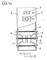
- FIG. 1b shows the same arrangement from FIG. 1a, but here the entire assembly, consisting of the sound transducers 4, 5 and the connections 6, 7, 8, 9, is connected to the sound guide 1 via suspensions 12, 13. There is an annular gap between the sound transducers 4, 5 and the sound guide 1, which is sealed with damping elastic seals 14, 15. Stops 17, 18 limit strong movements of the assembly when the loudspeaker is being transported. In contrast to the arrangement of Fig.la, the transmission of vibrations of the chassis of the sound transducers 4, 5 to the sound guide 1 is prevented even if the forces are not completely compensated for to zero. This is the case, for example, if the connections 6, 7, 8, 9 have elastic properties and thus yield to the forces acting on them.
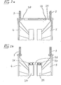
- FIG. 2a shows an example of the many possible embodiments of the mechanical connection between the sound transducers 4, 5. Only one of the connecting elements that are present several times (mostly four times) is shown. This is a version that is adjustable in length.
- a rod 21 is inserted into a tube 20 with a good fit.
- a locking ring 22 fixes the rod 21 and tube 20 together.
- the free ends of the rod 21 and the tube 20 are expediently provided with threads that enable a screw connection with the sound transducers 4, 5 and the sound guide 1.
- the locking ring 22 contains two different internal threads, each of which fit on the external threads of the tube 20 and the rod 21.
- the simplest embodiment is to dispense with the tube 20 and to design the rod 21 as a continuous threaded rod, which is cut to the length required in each case.
- FIG. 2b shows another example for the execution of the mechanical connection between the sound transducers 4, 5. Again, only one of the multiple connections is shown.
- the magnets 24, 25 of the sound transducers 4, 5 are provided with tabs 26, 27 to which a connecting piece 28 is fastened by means of screw connections.
- This version is characterized by its minimal length, which makes the elastic properties of the material less effective.
- FIG. 3 shows the arrangement of three sound transducers 32, 33, 34 with their mutual mechanical connection 35 using the example of an all-round radiating loudspeaker box 31, which is shown in partial cross section and in perspective. Due to the point symmetry of the arrangement voltage and with the same data of the sound transducers 32, 33, 34, their dynamic forces on the sound guide 31 compensate for zero. The principle of action, which is shown for the mirror-symmetrical arrangement of the sound transducers in Fig.1a, applies accordingly for the point-symmetrical arrangement with more than two sound transducers.
- the mechanical connection 35 is somewhat more complex here, since connecting rods which lie outside the center plane of the respective sound transducer must be connected to one another in order to be able to absorb lateral forces.
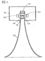
- a horn loudspeaker box is shown in FIG.
- Sound transducers 42, 43 which are connected to one another via mechanical connections 44, 45, 46, 47 (47 hidden behind 45) and are closed at the rear by a sound guide 41, work as drivers for the horn sound guide 40. In this arrangement, more than two sound transducers can be combined.
- FIG. 5 shows a three-way speaker in partial longitudinal section from the front and from the side.
- a sound guide 50 contains a high-frequency sound transducer 51, a mid-range sound transducer 52 and, instead of a pair of large low-frequency sound transducers, three pairs of small low-frequency sound transducers 53, 54, 55, 56, 57, 58.
- This arrangement ensures that the low-frequency sound transducers emit better towards the front, which is naturally difficult due to the lateral installation at higher frequencies and can only be improved by smaller diaphragm diameters.
- Front radiation occurs when the membrane is smaller than the smallest wavelength to be emitted.
- FIG. 6 shows a pentagonal speaker box in partial cross section.
- Sound transducers 61, 62 are installed in a sound guide 60 and are connected to one another by mechanical connections 63, 64, 65 (65 hidden behind 63). Due to the geometry of the sound guide 60, the sound transducers 61, 62 are inclined at an angle to each other. As a result, the mutual compensation of the forces is not zero, a residual component remains.
- the example is intended to show that even in loudspeakers in which the sound transducers are not exactly parallel to one another, it makes sense to mechanically connect the sound transducers to one another, because this at least reduces the forces on the sound guidance. The effectiveness of the measure depends on the angle between the transducers.
- FIG. 7a shows a three-way loudspeaker box in partial cross section.
- a sound guide 70 designed as a closed box contains, in addition to the high and middle ion transducers 71, 72, a low-frequency transducer -73, which is connected to a low-frequency transducer 74 by means of mechanical connections 75, 76, 77, 78 (78 rear 76 hidden) previous examples is mounted on the front of the S challwandler 73 and radiates acoustic from, while the transducer 74 is mounted in the interior of the sound guide 70, and not sound outwardly abstrahlt.Er serves only to compensate for the impact sound of the sound transducer 73.
- This embodiment is particularly suitable for naeh Creden Installation in existing loudspeakers. It is further characterized by the fact that the usual construction of loudspeakers with their typical appearance can be retained. On the other hand, it must be taken into account that in this embodiment, in contrast to the previous examples, the overall efficiency is lower, which is particularly important in the case of passive laser speakers.
- Figure 7b shows the principle of the electrical wiring of the speaker box of Figure 7a as a passive box.
- the input signal passes through a Freque nzweiche to the individual transducers 71,72,73 and above it b a potentiometer configured as a T-79 controller 74 to the transducer with the This potentiometer 79 is adjusted for the best possible compensation.
- the design as a T-actuator ensures constant impedance in the entire setting range and thus avoids effects on the crossover. Wiring examples for active loudspeakers follow in FIGS. 9a-c.
- FIG. 8 ′ shows a possible improved embodiment of the arrangement according to FIG. 7a in half cross-section.
- a sound transducer 81 is connected to a special compensation transducer 85 via brackets 83, 84, which at the same time serve for fastening with a sound guide 80.
- a sound transducer for compensation this need not be a transducer in the usual sense because it should emit no sound.
- the membrane and the basket can be omitted.
- the drive system here: magnet, voice coil, centering
- a special compensation transducer 85 is thus obtained, which is designed to be far less complex than a normal sound transducer.
- the compensation transducer 85 is connected to the actual sound transducer 81 to form an integral unit which avoids problems of mechanical and dynamic mutual adaptation. Furthermore, it is advantageous to connect the entire unit to the sound guide 80 via the fastenings 83, 84. On the one hand, this is a vibration-neutral suspension, on the other hand, the chassis of the sound transducer 81 can be made cheaper.
- Figures 9a-c show block diagrams for different wiring options of an active loudspeaker box according to Fig. 8 or Fig. 7a.
- the input signal of the respective circuit is the signal coming from the crossover, which is assigned to the sound converter 81.
- this signal hangs over a power output stronger 90 to the sound transducer 81 and parallel to it via an equalizer 92 to a second power amplifier 91 and to the compensation transducer 85.
- the advantage of this circuit compared to a simple parallel connection of the transducers 81, 85 is that the equalizer 92 makes differences in the frequency responses of the transducers 81, 85 can be compensated. This equalization is usually easier to implement and adjust when the circuit is active than with a passive circuit, such as in Fig. 7b. Since the converter 85 is not used for sound radiation, a simpler and cheaper design is sufficient for the power amplifier 91 than for the amplifier 90.
- the input signal again reaches the sound transducer 81 via the amplifier 90.
- a measuring device 94 supplies a signal via a measuring amplifier 93 which corresponds to the membrane amplitude of the sound transducer 81.
- This signal passes through the power amplifier 91 to the compensation converter 85.
- the measuring amplifier can contain an equalization which corrects irregularities in the frequency response of the converter 85.
- Different types of transducers 81, sound guides, changes in acoustic load, etc. are automatically taken into account here.
Landscapes
- Physics & Mathematics (AREA)
- Engineering & Computer Science (AREA)
- Acoustics & Sound (AREA)
- Signal Processing (AREA)
- Health & Medical Sciences (AREA)
- Otolaryngology (AREA)
- Details Of Audible-Bandwidth Transducers (AREA)
- Obtaining Desirable Characteristics In Audible-Bandwidth Transducers (AREA)
- Circuit For Audible Band Transducer (AREA)
Priority Applications (1)
| Application Number | Priority Date | Filing Date | Title |
|---|---|---|---|
| AT85104406T ATE91211T1 (de) | 1984-04-17 | 1985-04-12 | Einbau von schallwandlern in eine schallfuehrung, insbesondere fuer lautsprecher, vorzugsweise fuer lautsprecherboxen. |
Applications Claiming Priority (2)
| Application Number | Priority Date | Filing Date | Title |
|---|---|---|---|
| DE3414407 | 1984-04-17 | ||
| DE3414407A DE3414407C2 (de) | 1984-04-17 | 1984-04-17 | Anordnung von Schallwandlern in einer Schallführung, insbesondere für Lautsprecherboxen |
Publications (3)
| Publication Number | Publication Date |
|---|---|
| EP0158978A2 true EP0158978A2 (fr) | 1985-10-23 |
| EP0158978A3 EP0158978A3 (en) | 1987-09-16 |
| EP0158978B1 EP0158978B1 (fr) | 1993-06-30 |
Family
ID=6233765
Family Applications (1)
| Application Number | Title | Priority Date | Filing Date |
|---|---|---|---|
| EP85104406A Expired - Lifetime EP0158978B1 (fr) | 1984-04-17 | 1985-04-12 | Montage de transducteurs dans un baffle, en particulier pour haut-parleurs, de préférence pour enceintes acoustiques |
Country Status (5)
| Country | Link |
|---|---|
| US (1) | US4805221A (fr) |
| EP (1) | EP0158978B1 (fr) |
| JP (1) | JPS61147700A (fr) |
| AT (1) | ATE91211T1 (fr) |
| DE (2) | DE3414407C2 (fr) |
Cited By (5)
| Publication number | Priority date | Publication date | Assignee | Title |
|---|---|---|---|---|
| EP0188295A3 (fr) * | 1985-01-03 | 1988-08-24 | Johan Peter Lyngdorf | Unité de haut-parleur |
| EP0505344A1 (fr) * | 1991-03-19 | 1992-09-23 | Ivan Schellekens | Dispositif de reproduction du son sans distorsion mecanique intermodulaire |
| EP0516471A1 (fr) * | 1991-05-31 | 1992-12-02 | Kh Technology Corporation | Système magnétique de commande pour haut-parleur |
| EP1601230A3 (fr) * | 2004-05-24 | 2009-08-26 | Blast Loudspeakers Ltd. | Système haut-parleur |
| US20240284098A1 (en) * | 2023-01-31 | 2024-08-22 | Jong Bae Lee | Multiple-driver adapter having plane wave equalizer |
Families Citing this family (35)
| Publication number | Priority date | Publication date | Assignee | Title |
|---|---|---|---|---|
| JPS63212296A (ja) * | 1987-02-27 | 1988-09-05 | Pioneer Electronic Corp | スピ−カシステム |
| EP0410352B1 (fr) * | 1989-07-24 | 1994-09-28 | Matsushita Electric Industrial Co., Ltd. | Système d'haut-parleur |
| NL8902831A (nl) * | 1989-11-16 | 1991-06-17 | Philips Nv | Luidsprekersysteem bevattende een helmholtz resonator gekoppeld met een akoestische buis. |
| US5210802A (en) * | 1990-04-30 | 1993-05-11 | Bose Corporation | Acoustic imaging |
| TW203674B (fr) * | 1991-07-09 | 1993-04-11 | Tong Hoon Sohn | |
| US5343535A (en) * | 1993-05-07 | 1994-08-30 | Marshall Ronald N | Loudspeaker device |
| US5502772A (en) * | 1994-07-18 | 1996-03-26 | Felder; Charles J. | Speaker having improved sound square, sound bank, sound angle, sound wedge and sound radiators |
| US5809153A (en) * | 1996-12-04 | 1998-09-15 | Bose Corporation | Electroacoustical transducing |
| US5815589A (en) * | 1997-02-18 | 1998-09-29 | Wainwright; Charles E. | Push-pull transmission line loudspeaker |
| EP1033061A1 (fr) * | 1997-10-02 | 2000-09-06 | Earl R. Geddes | Enceinte de transducteur basse frequence amelioree |
| US7212644B2 (en) * | 2000-05-26 | 2007-05-01 | California Institute Of Technology | Resonant frequency adjustment using tunable damping rods |
| JP2001352592A (ja) * | 2000-06-08 | 2001-12-21 | Fujitsu Ten Ltd | スピーカ構造 |
| JP4064160B2 (ja) * | 2002-06-07 | 2008-03-19 | 富士通テン株式会社 | スピーカ装置 |
| CZ301578B6 (cs) * | 2005-02-25 | 2010-04-21 | Šroll@Ludek | Reproduktorová soustava vyzarující válcovou akustickou vlnu |
| US20070030992A1 (en) * | 2005-08-03 | 2007-02-08 | Rauen Kenneth M | Low frequency loudspeaker enclosure |
| US7668331B2 (en) * | 2005-10-07 | 2010-02-23 | Wailit Yen | Fidelity speaker |
| US20070158134A1 (en) * | 2006-01-11 | 2007-07-12 | Fryette Steven M | Speaker cabinet acoustics control mechanism |
| US7881488B2 (en) * | 2006-11-01 | 2011-02-01 | Bose Corporation | In-plane speaker |
| US20080110320A1 (en) * | 2006-11-13 | 2008-05-15 | Boone Cheynetta L | Matter for the all aluminum housing used for producing sound |
| WO2009039852A1 (fr) * | 2007-09-28 | 2009-04-02 | Lennart Jarde | Système d'émission sonore isobare |
| US20090084866A1 (en) * | 2007-10-01 | 2009-04-02 | Nuventix Inc. | Vibration balanced synthetic jet ejector |
| US20120057734A1 (en) * | 2008-07-23 | 2012-03-08 | Asius Technologies, Llc | Hearing Device System and Method |
| US20100246880A1 (en) * | 2009-03-30 | 2010-09-30 | Oxford J Craig | Method and apparatus for enhanced stimulation of the limbic auditory response |
| GB2491108B (en) | 2011-05-18 | 2014-06-04 | Gp Acoustics Uk Ltd | Loudspeaker |
| US9503806B2 (en) | 2012-03-27 | 2016-11-22 | Joseph B Crosswell | Loudspeaker system audio recovery imaging amplifier |
| EP2974356B1 (fr) * | 2013-03-13 | 2020-05-06 | THX Ltd | Haut-parleur compact |
| NL1040501C2 (en) * | 2013-11-15 | 2015-05-19 | Qsources Bvba | Device for creating a sound source. |
| FR3087067B1 (fr) * | 2018-10-08 | 2022-02-25 | Devialet | Enceinte acoustique a deux haut-parleurs tete-beche fixes sur une armature interne |
| FR3087071B1 (fr) | 2018-10-08 | 2020-11-06 | Devialet | Enceinte acoustique comportant une coque en matiere plastique monobloc |
| FR3089380B1 (fr) * | 2018-12-03 | 2020-11-20 | Sagemcom Broadband Sas | Pièce de rigidification pour caisson d’enceinte acoustique |
| EP3726849B1 (fr) * | 2019-04-15 | 2024-07-24 | Harman Becker Automotive Systems GmbH | Agencement de haut-parleur |
| CN110719549A (zh) * | 2019-10-15 | 2020-01-21 | 李世煌 | 一种立体声音箱和立体声系统 |
| GB2591223A (en) | 2020-01-22 | 2021-07-28 | Gp Acoustics International Ltd | Loudspeakers |
| EP4207797A1 (fr) * | 2021-12-30 | 2023-07-05 | Harman Becker Automotive Systems GmbH | Haut-parleur |
| NL1044443B1 (nl) * | 2022-10-26 | 2024-05-14 | Rob Meijst Drs | Luidsprekersysteem met per kanaal twee luidsprekers in afzonderlijke kasten, met deflectieorganen ertussen voor geluidsexcitatie in dwarsrichting |
Family Cites Families (28)
| Publication number | Priority date | Publication date | Assignee | Title |
|---|---|---|---|---|
| US2108846A (en) * | 1934-08-29 | 1938-02-22 | Walter O Brown | Radio cabinet |
| US2041777A (en) * | 1935-07-10 | 1936-05-26 | Stromberg Carlson Telephone | Sound reproducing system |
| US2072035A (en) * | 1936-02-13 | 1937-02-23 | Richard O Bohannon | Sound damping device for loudspeakers |
| GB659066A (en) * | 1947-11-06 | 1951-10-17 | Ian Irvine Boswell | Improvements in or relating to electro-mechanical transducers |
| US2835735A (en) * | 1953-12-04 | 1958-05-20 | Electro Voice | Anti-shock transducer |
| US3064086A (en) * | 1961-01-31 | 1962-11-13 | Audio Tours Inc | Loud-speaker enclosures |
| US3393764A (en) * | 1966-12-27 | 1968-07-23 | Curtiss R. Schafer | Loudspeaker systems |
| FR1527032A (fr) * | 1967-04-03 | 1968-05-31 | Convertisseur électro-acoustique | |
| US3781475A (en) * | 1971-05-26 | 1973-12-25 | Columbia Broadcasting Syst Inc | Counterbalanced two speaker rotary tremolo device |
| FR2241942B1 (fr) * | 1973-08-24 | 1976-05-07 | Tretiakoff Oleg | |
| US3909531A (en) * | 1974-03-25 | 1975-09-30 | Custom Electronics Inc | Acoustic transducer system |
| JPS5245324A (en) * | 1975-08-04 | 1977-04-09 | Kenji Isozumi | Speaker showing no vibration |
| FR2380704A7 (fr) * | 1977-02-11 | 1978-09-08 | Audax | Enceinte acoustique |
| US4379951A (en) * | 1977-04-20 | 1983-04-12 | Gabr Saad Z M | Electro-acoustic transducer means |
| DE2725346C3 (de) * | 1977-06-04 | 1981-05-14 | Josef Wilhelm 8725 Arnstein Manger | Lautsprecher |
| JPS606157B2 (ja) * | 1977-07-25 | 1985-02-15 | ソニー株式会社 | スピ−カ |
| DE2837520A1 (de) * | 1978-08-28 | 1980-03-27 | Harald Schuster | Lautsprecher, passiv servokontrolliert mit korrektur der phasendrehung |
| DE2847446A1 (de) * | 1978-11-02 | 1980-05-22 | Eric Faesecke Kg | Lautsprecherbox |
| NL8001592A (nl) * | 1980-03-18 | 1981-10-16 | Philips Nv | Mfb systeem met een overnamenetwerk. |
| DE3037227A1 (de) * | 1980-10-02 | 1982-04-29 | Alfred 2800 Bremen Rinkowski | Lautsprecher mit koerperschallresonator |
| US4420061A (en) * | 1980-11-03 | 1983-12-13 | Michael Levy | Pentagonal speaker enclosure with a downward directed dynamic damping system |
| DE3172790D1 (en) * | 1980-12-19 | 1985-12-05 | Nissan Motor | Speaker for automotive vehicle audio system |
| US4451711A (en) * | 1981-05-07 | 1984-05-29 | Mark Jackson | Readily portable speaker enclosure |
| DE3141167A1 (de) * | 1981-10-13 | 1983-04-28 | Alfred 2800 Bremen Rinkowski | Lautsprecheranordnung, mit gehaeuse |
| CH645227A5 (fr) * | 1981-12-22 | 1984-09-14 | Multiphonie Sa | Transducteur electro-acoustique. |
| GB2122051A (en) * | 1982-06-01 | 1984-01-04 | Goodmans Loudspeakers Limited | Loudspeaker systems |
| FR2545674B1 (fr) * | 1983-05-02 | 1985-08-16 | Leguillou Denis | Enceinte acoustique pentagonale a tirants internes etoiles autoporteurs |
| DK156454C (da) * | 1985-01-03 | 1990-01-15 | Johan Peter Lyngdorf | Hoejttalerenhed med mere end en bas/mellemtone-hoejttaler |
-
1984
- 1984-04-17 DE DE3414407A patent/DE3414407C2/de not_active Expired
-
1985
- 1985-04-12 EP EP85104406A patent/EP0158978B1/fr not_active Expired - Lifetime
- 1985-04-12 DE DE8585104406T patent/DE3587425D1/de not_active Expired - Fee Related
- 1985-04-12 AT AT85104406T patent/ATE91211T1/de not_active IP Right Cessation
- 1985-04-16 US US06/723,825 patent/US4805221A/en not_active Expired - Fee Related
- 1985-04-17 JP JP60082124A patent/JPS61147700A/ja active Pending
Cited By (8)
| Publication number | Priority date | Publication date | Assignee | Title |
|---|---|---|---|---|
| EP0188295A3 (fr) * | 1985-01-03 | 1988-08-24 | Johan Peter Lyngdorf | Unité de haut-parleur |
| EP0505344A1 (fr) * | 1991-03-19 | 1992-09-23 | Ivan Schellekens | Dispositif de reproduction du son sans distorsion mecanique intermodulaire |
| BE1004807A3 (nl) * | 1991-03-19 | 1993-02-02 | Schellekens Ivan | Het weergeven van geluid zonder mechanische intermodulatievervorming. |
| EP0516471A1 (fr) * | 1991-05-31 | 1992-12-02 | Kh Technology Corporation | Système magnétique de commande pour haut-parleur |
| WO1992022175A1 (fr) * | 1991-05-31 | 1992-12-10 | Kef Audio (Uk) Limited | Systeme d'attaque magnetique pour haut-parleur |
| EP1601230A3 (fr) * | 2004-05-24 | 2009-08-26 | Blast Loudspeakers Ltd. | Système haut-parleur |
| US20240284098A1 (en) * | 2023-01-31 | 2024-08-22 | Jong Bae Lee | Multiple-driver adapter having plane wave equalizer |
| US12225346B2 (en) * | 2023-01-31 | 2025-02-11 | Jong Bae Lee | Multiple-driver adapter having plane wave equalizer |
Also Published As
| Publication number | Publication date |
|---|---|
| JPS61147700A (ja) | 1986-07-05 |
| DE3414407C2 (de) | 1986-02-20 |
| US4805221A (en) | 1989-02-14 |
| EP0158978B1 (fr) | 1993-06-30 |
| EP0158978A3 (en) | 1987-09-16 |
| DE3414407A1 (de) | 1985-10-24 |
| DE3587425D1 (de) | 1993-08-05 |
| ATE91211T1 (de) | 1993-07-15 |
Similar Documents
| Publication | Publication Date | Title |
|---|---|---|
| EP0158978B1 (fr) | Montage de transducteurs dans un baffle, en particulier pour haut-parleurs, de préférence pour enceintes acoustiques | |
| DE60315547T2 (de) | Lautsprecheranordnung | |
| DE3023291C2 (fr) | ||
| DE3404655A1 (de) | Vorrichtung zur uebertragung von druckwellen | |
| DE68908766T2 (de) | Tonanlage, besonders zur stereophonen Tonwiedergabe in einem Fernsehempfangsgerät mit integriertem Tieftonlautsprecher grosser Dimensionen. | |
| DE2451307A1 (de) | Mikrofon | |
| DE2057905B1 (de) | Lautsprecheranordnung mit von einem Antriebssystem angetriebener Hochton- und Tieftonmembran | |
| DE2354614A1 (de) | Passive abstrahlungsmembran | |
| DE3231622C2 (de) | Bassreflex-Lautsprechersystem | |
| DE2726184A1 (de) | Lautsprecher | |
| EP2811756A1 (fr) | Haut-parleur | |
| EP1169884B1 (fr) | Haut-parleur plan et son procede de production | |
| DE10027618B4 (de) | Schallwandler | |
| DE202014009095U1 (de) | Lautsprecherbox mit veränderlicher Richtwirkung für die mittleren- und hohen Frequenzen | |
| DE3733095A1 (de) | Stereoeinrichtung mit einem piezoelektrischen membranlautsprecher | |
| DE69938142T2 (de) | Verfahren zur tonwiedergabe und säulenlautsprecher | |
| DE2809052C2 (fr) | ||
| DE102012025422B4 (de) | Vorrichtung zur Resonanzminimierung von Gehäusen | |
| DE3506139C1 (de) | Lautsprechersystem für eine qualitativ hochwertige Tonwiedergabe | |
| EP1965602B1 (fr) | Enceinte acoustique | |
| EP1142445A2 (fr) | Haut-parleur a membrane de graves | |
| DE69211196T2 (de) | Klangwiedergabevorrichtung ohne mechanische Intermodulation- verzerrung | |
| DE3918654C2 (fr) | ||
| DE3130789C2 (de) | Lautsprecherbox mit akustisch gleichphasig gekoppelten Treibern bei gleichzeitiger Ausnutzung der rückwärtigen Schallanteile | |
| DE212023000436U1 (de) | Kompensierbarer pneumatischer Treiber |
Legal Events
| Date | Code | Title | Description |
|---|---|---|---|
| PUAI | Public reference made under article 153(3) epc to a published international application that has entered the european phase |
Free format text: ORIGINAL CODE: 0009012 |
|
| AK | Designated contracting states |
Designated state(s): AT BE CH DE FR GB IT LI LU NL SE |
|
| 17P | Request for examination filed |
Effective date: 19860318 |
|
| RAP1 | Party data changed (applicant data changed or rights of an application transferred) |
Owner name: QUAAS, JUERGEN |
|
| PUAL | Search report despatched |
Free format text: ORIGINAL CODE: 0009013 |
|
| AK | Designated contracting states |
Kind code of ref document: A3 Designated state(s): AT BE CH DE FR GB IT LI LU NL SE |
|
| RAP3 | Party data changed (applicant data changed or rights of an application transferred) |
Owner name: QUAAS, JUERGEN, DIPL.-ING. |
|
| 17Q | First examination report despatched |
Effective date: 19890301 |
|
| GRAA | (expected) grant |
Free format text: ORIGINAL CODE: 0009210 |
|
| AK | Designated contracting states |
Kind code of ref document: B1 Designated state(s): AT BE CH DE FR GB IT LI LU NL SE |
|
| PG25 | Lapsed in a contracting state [announced via postgrant information from national office to epo] |
Ref country code: SE Effective date: 19930630 Ref country code: NL Effective date: 19930630 Ref country code: IT Free format text: LAPSE BECAUSE OF FAILURE TO SUBMIT A TRANSLATION OF THE DESCRIPTION OR TO PAY THE FEE WITHIN THE PRESCRIBED TIME-LIMIT;WARNING: LAPSES OF ITALIAN PATENTS WITH EFFECTIVE DATE BEFORE 2007 MAY HAVE OCCURRED AT ANY TIME BEFORE 2007. THE CORRECT EFFECTIVE DATE MAY BE DIFFERENT FROM THE ONE RECORDED. Effective date: 19930630 Ref country code: GB Effective date: 19930630 Ref country code: FR Effective date: 19930630 Ref country code: BE Effective date: 19930630 |
|
| REF | Corresponds to: |
Ref document number: 91211 Country of ref document: AT Date of ref document: 19930715 Kind code of ref document: T |
|
| REF | Corresponds to: |
Ref document number: 3587425 Country of ref document: DE Date of ref document: 19930805 |
|
| EN | Fr: translation not filed | ||
| NLV1 | Nl: lapsed or annulled due to failure to fulfill the requirements of art. 29p and 29m of the patents act | ||
| GBV | Gb: ep patent (uk) treated as always having been void in accordance with gb section 77(7)/1977 [no translation filed] |
Effective date: 19930630 |
|
| PG25 | Lapsed in a contracting state [announced via postgrant information from national office to epo] |
Ref country code: AT Effective date: 19940412 |
|
| PG25 | Lapsed in a contracting state [announced via postgrant information from national office to epo] |
Ref country code: LU Free format text: LAPSE BECAUSE OF NON-PAYMENT OF DUE FEES Effective date: 19940430 |
|
| PLBE | No opposition filed within time limit |
Free format text: ORIGINAL CODE: 0009261 |
|
| STAA | Information on the status of an ep patent application or granted ep patent |
Free format text: STATUS: NO OPPOSITION FILED WITHIN TIME LIMIT |
|
| 26N | No opposition filed | ||
| PGFP | Annual fee paid to national office [announced via postgrant information from national office to epo] |
Ref country code: CH Payment date: 19990628 Year of fee payment: 15 |
|
| PG25 | Lapsed in a contracting state [announced via postgrant information from national office to epo] |
Ref country code: LI Free format text: LAPSE BECAUSE OF NON-PAYMENT OF DUE FEES Effective date: 20000430 Ref country code: CH Free format text: LAPSE BECAUSE OF NON-PAYMENT OF DUE FEES Effective date: 20000430 |
|
| REG | Reference to a national code |
Ref country code: CH Ref legal event code: PL |
|
| PGFP | Annual fee paid to national office [announced via postgrant information from national office to epo] |
Ref country code: DE Payment date: 20030626 Year of fee payment: 19 |
|
| PG25 | Lapsed in a contracting state [announced via postgrant information from national office to epo] |
Ref country code: DE Free format text: LAPSE BECAUSE OF NON-PAYMENT OF DUE FEES Effective date: 20041103 |