EP0159019A2 - Automatische und autonome Kläranlage mit rotierender Treibriemenscheidung und externer Radialzirkulation - Google Patents
Automatische und autonome Kläranlage mit rotierender Treibriemenscheidung und externer Radialzirkulation Download PDFInfo
- Publication number
- EP0159019A2 EP0159019A2 EP85104607A EP85104607A EP0159019A2 EP 0159019 A2 EP0159019 A2 EP 0159019A2 EP 85104607 A EP85104607 A EP 85104607A EP 85104607 A EP85104607 A EP 85104607A EP 0159019 A2 EP0159019 A2 EP 0159019A2
- Authority
- EP
- European Patent Office
- Prior art keywords
- water
- purifier
- pollutants
- pumps
- boxes
- Prior art date
- Legal status (The legal status is an assumption and is not a legal conclusion. Google has not performed a legal analysis and makes no representation as to the accuracy of the status listed.)
- Withdrawn
Links
Images

Classifications
-
- E—FIXED CONSTRUCTIONS
- E02—HYDRAULIC ENGINEERING; FOUNDATIONS; SOIL SHIFTING
- E02B—HYDRAULIC ENGINEERING
- E02B15/00—Cleaning or keeping clear the surface of open water; Apparatus therefor
- E02B15/04—Devices for cleaning or keeping clear the surface of open water from oil or like floating materials by separating or removing these materials
- E02B15/10—Devices for removing the material from the surface
- E02B15/101—Means floating loosely on the water absorbing the oil
-
- E—FIXED CONSTRUCTIONS
- E02—HYDRAULIC ENGINEERING; FOUNDATIONS; SOIL SHIFTING
- E02B—HYDRAULIC ENGINEERING
- E02B15/00—Cleaning or keeping clear the surface of open water; Apparatus therefor
- E02B15/04—Devices for cleaning or keeping clear the surface of open water from oil or like floating materials by separating or removing these materials
- E02B15/10—Devices for removing the material from the surface
- E02B15/104—Conveyors; Paddle wheels; Endless belts
-
- E—FIXED CONSTRUCTIONS
- E02—HYDRAULIC ENGINEERING; FOUNDATIONS; SOIL SHIFTING
- E02B—HYDRAULIC ENGINEERING
- E02B15/00—Cleaning or keeping clear the surface of open water; Apparatus therefor
- E02B15/04—Devices for cleaning or keeping clear the surface of open water from oil or like floating materials by separating or removing these materials
- E02B15/10—Devices for removing the material from the surface
- E02B15/106—Overflow skimmers with suction heads; suction heads
-
- E—FIXED CONSTRUCTIONS
- E02—HYDRAULIC ENGINEERING; FOUNDATIONS; SOIL SHIFTING
- E02B—HYDRAULIC ENGINEERING
- E02B15/00—Cleaning or keeping clear the surface of open water; Apparatus therefor
- E02B15/04—Devices for cleaning or keeping clear the surface of open water from oil or like floating materials by separating or removing these materials
- E02B15/10—Devices for removing the material from the surface
- E02B15/108—Ejection means
-
- Y—GENERAL TAGGING OF NEW TECHNOLOGICAL DEVELOPMENTS; GENERAL TAGGING OF CROSS-SECTIONAL TECHNOLOGIES SPANNING OVER SEVERAL SECTIONS OF THE IPC; TECHNICAL SUBJECTS COVERED BY FORMER USPC CROSS-REFERENCE ART COLLECTIONS [XRACs] AND DIGESTS
- Y02—TECHNOLOGIES OR APPLICATIONS FOR MITIGATION OR ADAPTATION AGAINST CLIMATE CHANGE
- Y02A—TECHNOLOGIES FOR ADAPTATION TO CLIMATE CHANGE
- Y02A20/00—Water conservation; Efficient water supply; Efficient water use
- Y02A20/20—Controlling water pollution; Waste water treatment
- Y02A20/204—Keeping clear the surface of open water from oil spills
Definitions
- This Patent covers an automatic and autonomous floating purifier for the removal of pollutants (especially oil spills) from water sheets.
- a recent automatic floating purifying system is known from the Italian Patent Application n O 12634 A/82, consisting of a floating box, preferably having a cylindrical watertight configuration, emerging above the water surface like a buoy, with numerous suction intakes along its circumference at waterline level; all water and pollutants penetrating through these inlet openings will reach a settling tank where the pollutant is separated from the water; the purified water is discharged, whereas the pollutants are collected in an upper dome, called “container" and can be recovered.
- a first disadvantage lies in the fact that water/im- purity separation by settlement is extremely slow and normally requires stopping of the cleaning operations.
- a second disadvantage derives from the fact that an optimum separation is impossible, even after settlement, since the purified water still contains an amount of pollutant, whereas the pollutant still contains a certain amount of water.
- purifying systems are not self- propelled so that they always need a tender acting as a tug and as a slop collector.
- This Patent has the aim to provide for a Boating purifying system without the above mentioned drawbacks.
- this aim is achieved by means of a floating purifier, in which separation is not obtained by natural settlement but with the aid of belts removing the pollutants by surface adhesion (such as for instance oil spills), with excellent results and in very short time.
- the purifying action is heightened by powerful circulation of the water aspirated from the water surface along the perimeter of the purifier.
- the water is then radially cast back in strong jets penetrating deep in the water, thus naturally accumulating and approaching the surface pollutants towards the purifier and extending its range of action so that the system is also efficient during transfer.
- the purifier is also capable of independent transfer, without separate propelling craft, since the radial water jets of the circulating water can act as ejectors when partially operated.
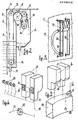
- the watertight housing of the purifier 1 is suitably ballasted 2, so that it can float at the desired depth below the water level L.
- the purifier 1 is housing and electric generator 3, complete with fuel tank and all accessories, to ensure independent energy supply for propulsion.
- the purifier features numerous compartments 4, separated from each other, in which the water is purified.
- Each of these compartments 4, illustrated in detail in Fig. 2, has two separate chambers, the first of which 5 is deeper than the-other and is communicating with the outside by 6 outlet openings, whereas the other chamber 7 is collecting the pollutants.
- the continuous belt 8 moving through both chambers 5 and 7 is supported by rolls 9, at least one of which is motor-driven, for instance the central roll 9' featuring a peripheral toothing to guide the belt and meshing with the corresponding holes.
- the belt passes through the polluted water in the chamber 5 and is cleaned in the chamber 7 by special cleaning devices 10.
- Both chamber 5 and 7 have bottom drains 11 and 12 respectively.
- Numerous floating boxes 13 are located outside the purifier, drawing the polluted water in, peripherally. These boxes 13 are always floating on the water surface and they can move vertically by means of sliders mounted on fixed frames 14. Obviously, these boxes can also be kept floating by means of articulated arms.
- Each box 13 discharges the polluted water through a flexible hose 15 and union 16 into the purifier.
- Each pump 17 has a suction line 18 connected to the drain of some boxes 13 and the discharge 11 of some of the chambers 5 of the compartments 4, whereas the delivery line 19 discharges radially outside the purifier well below the water surface.
- the purifier 1 also features a tank 20, anular shaped for exemplification purposes, in which the pollutants are collected.
- This tank 20 receives the slop 12 drained from the chambers 7 of the various compartments 4.
- the pollutant is pumped from the tank 20 by normal or plunger pumps 21 fitted with a foot valve 22 and conveyed through the hose 23 into a tender ship or shore-based tanks. Pumping may be continuous or intermittent.
- the purifier equipment also includes inspection doors, guards 24, navigation and safety aids, a nose 25 fitted with the fender to prevent impact with the ship or quay, a receiving antenna 26, signal lamps 27 and an emergency light 28.
- An antiflooding pump 29 is mounted on the bottom.
- An air vent 30 is mounted on top of the purifier.
- the operation of the purifier is thus clearly explained.
- the water discharged from the boxes 13 and chambers 5 in the compartments 4 is radially and pe- ripwrally discharged by the high capacity circulating pumps 17 below the water surface L.
- This circulation thus creates a toroidal flow converging at the surface towards the purifier and enormously boosting its efficiency.
- the water conveys the pollutants towards the openings 6, letting the slop into the chambers 5 of the belt separation compartments 4.
- the pollutants are thus accumulated in these chambers coming from a vide area around the purifier.
- the belts will remove the pollutants which stick to the belts in question.
- peripheral radial jets created by the circulating pumps 17 can also be used for propulsion and steering of the purifier. This can be achieved by operating at the same time all pumps 17 which will keep the purifier in place since the various flows will counterbalance each other, while operation of the pumps on one side only and stopping of the pumps located on the opposite side will create a thrust driving the purifier in the required direction.
- the purifier may feature eight compartments 4 and sixteen boxes 13, the compartments being pairwise and the boxes being foursome connected to a circulating pump 17, as shown in Fig. 4, so that four of these are necessary.
- the number of compartments, boxes and circulating pumps 17 may be just any, according to the dimensions of the purifier.
- the tubes 19 may have nozzles. As shown in Fig. 5, all chambers 7 of the compartment 4 are directly discharging into the storage tank 20 in which the polluted liquid can remain even for a considerable period. This means that the purifier can also operate without tender ship or may discharge directly on shore, reaching the quay or pier autonomously from where the operations can be radio-controlled.
- the purifier in question is highly efficient and greatly reduces the time required to eliminate the oil spills or other pollutants due to its much wider range of action with respect to its dimensions and also because of its direct and mechanical oil/ water separation capacity without need to wait for settlement.and without need for towing.
- This purifier can be used in turning basins and water sheets in the sea, lakes, rivers and calm waters, but even in the open sea with wave motion up to scale 5 ("rough sea").
- the purifier in question can also be used for impounding backwaters, basins, for cleaning bilges, wells etc., or it can be installed on board of merchant and navy ships.
Landscapes
- Engineering & Computer Science (AREA)
- General Engineering & Computer Science (AREA)
- Environmental & Geological Engineering (AREA)
- Mechanical Engineering (AREA)
- Civil Engineering (AREA)
- Structural Engineering (AREA)
- Chemical & Material Sciences (AREA)
- Oil, Petroleum & Natural Gas (AREA)
- Removal Of Floating Material (AREA)
- Cleaning Or Clearing Of The Surface Of Open Water (AREA)
Applications Claiming Priority (2)
| Application Number | Priority Date | Filing Date | Title |
|---|---|---|---|
| IT12495/84A IT1180480B (it) | 1984-04-17 | 1984-04-17 | Depuratore galleggiante automatico ed autonomo con separazione a nastri rotanti e con cirolazione radiale esterna di accumulazione delle impurita galleggianti e di movimento |
| IT1249584 | 1984-04-17 |
Publications (2)
| Publication Number | Publication Date |
|---|---|
| EP0159019A2 true EP0159019A2 (de) | 1985-10-23 |
| EP0159019A3 EP0159019A3 (de) | 1987-07-29 |
Family
ID=11140838
Family Applications (1)
| Application Number | Title | Priority Date | Filing Date |
|---|---|---|---|
| EP85104607A Withdrawn EP0159019A3 (de) | 1984-04-17 | 1985-04-16 | Automatische und autonome Kläranlage mit rotierender Treibriemenscheidung und externer Radialzirkulation |
Country Status (5)
| Country | Link |
|---|---|
| US (1) | US4614582A (de) |
| EP (1) | EP0159019A3 (de) |
| JP (1) | JPS6118492A (de) |
| ES (1) | ES8606206A1 (de) |
| IT (1) | IT1180480B (de) |
Cited By (1)
| Publication number | Priority date | Publication date | Assignee | Title |
|---|---|---|---|---|
| WO1990012157A1 (en) * | 1989-04-03 | 1990-10-18 | Oy Larsen Marin Ab | An oil collecting unit |
Families Citing this family (7)
| Publication number | Priority date | Publication date | Assignee | Title |
|---|---|---|---|---|
| US4997557A (en) * | 1989-05-19 | 1991-03-05 | Aqua-Aerobic Systems, Inc. | Floating, mixing, aerating and decanting unit |
| US5053145A (en) * | 1990-05-03 | 1991-10-01 | Ellison Billy L | Dual direction transfer system for tramp oil collection |
| US5075014A (en) * | 1990-05-04 | 1991-12-24 | Imc-International Marketing Of Canada Corp. | Oil recovery system and apparatus |
| US5522990A (en) * | 1994-08-08 | 1996-06-04 | Davidian; Steven | Oil removal device with integrated gravity separator |
| US6269763B1 (en) * | 1998-02-20 | 2001-08-07 | Richard Lawrence Ken Woodland | Autonomous marine vehicle |
| WO2004090238A2 (en) * | 2003-04-07 | 2004-10-21 | Desmi A/S | Oil skimmer |
| MX2010008981A (es) * | 2008-02-16 | 2011-02-22 | Myron Ii Sullivan | Sistema y aparato para la recuperacion de petroleo. |
Family Cites Families (6)
| Publication number | Priority date | Publication date | Assignee | Title |
|---|---|---|---|---|
| CA988862A (en) * | 1970-09-21 | 1976-05-11 | Marine Construction And Design Co. | Method and apparatus for separating immiscible liquids |
| US4024063A (en) * | 1973-02-15 | 1977-05-17 | Kabushiki Kaisha World Chemical | Floating-matter removing apparatus |
| US4165282A (en) * | 1976-02-26 | 1979-08-21 | Bennett Pollution Controls Ltd. | Oil recovery method and apparatus |
| US4391707A (en) * | 1978-05-12 | 1983-07-05 | Zollco International, Inc. | Floating, surface liquids retrieval system |
| US4305830A (en) * | 1980-02-27 | 1981-12-15 | Arvin Fay Christensen | Water surface cleaner, method and apparatus |
| DE3022501A1 (de) * | 1980-06-14 | 1981-12-24 | Herbert 8130 Starnberg Ertl | Einrichtung zum absaugen von oel |
-
1984
- 1984-04-17 IT IT12495/84A patent/IT1180480B/it active
-
1985
- 1985-04-16 EP EP85104607A patent/EP0159019A3/de not_active Withdrawn
- 1985-04-17 US US06/724,018 patent/US4614582A/en not_active Expired - Fee Related
- 1985-04-17 JP JP60082092A patent/JPS6118492A/ja active Pending
- 1985-04-18 ES ES542403A patent/ES8606206A1/es not_active Expired
Cited By (2)
| Publication number | Priority date | Publication date | Assignee | Title |
|---|---|---|---|---|
| WO1990012157A1 (en) * | 1989-04-03 | 1990-10-18 | Oy Larsen Marin Ab | An oil collecting unit |
| US5137630A (en) * | 1989-04-03 | 1992-08-11 | Oy Larsen Marin Ab | Oil collecting unit |
Also Published As
| Publication number | Publication date |
|---|---|
| ES542403A0 (es) | 1986-04-01 |
| JPS6118492A (ja) | 1986-01-27 |
| EP0159019A3 (de) | 1987-07-29 |
| IT1180480B (it) | 1987-09-23 |
| IT8412495A0 (it) | 1984-04-17 |
| US4614582A (en) | 1986-09-30 |
| ES8606206A1 (es) | 1986-04-01 |
Similar Documents
| Publication | Publication Date | Title |
|---|---|---|
| US5128031A (en) | Pool surface skimmer | |
| US5022987A (en) | Apparatus and method for separating and removal of floating pollutants from a water surface | |
| US3847816A (en) | Pollution suction water sweeper | |
| US4851133A (en) | Method and apparatus for recovering low density liquids in surface water | |
| US3730346A (en) | Skimming system | |
| US3853768A (en) | Skimming apparatus | |
| US3731813A (en) | Floating debris recovery apparatus | |
| US5045216A (en) | Method, system and collecting vessel for oil spill recovery | |
| US3690464A (en) | Oil recovery vessel for the removal of oil and other polluting matter floating on the water surface | |
| US4614582A (en) | Automatic and autonomous floating purifier with rotary belt separation and external radial circulation | |
| US4477348A (en) | Open sea skimmer barge | |
| US4795567A (en) | Oil spill separating and recovery system | |
| KR100239829B1 (ko) | 해상 유출기름 수거처리장치 및 처리방법 | |
| US3661263A (en) | Apparatus for separating an oil slick from a large body of water | |
| US3534858A (en) | Pollution control device | |
| US3682316A (en) | Apparatus for the collection of buoyant foreign matter | |
| FI123745B (fi) | Laitteisto ja menetelmä materiaalin keräämiseksi vesistöstä | |
| US4053414A (en) | Oil recovery apparatus | |
| US6793807B2 (en) | Liquid pollutant skimming system | |
| US4399040A (en) | Open sea skimmer barge | |
| US5194151A (en) | Oil skimmer | |
| RU2462555C1 (ru) | Плавучее устройство для сбора разлитой по воде нефти | |
| US5122283A (en) | Apparatus and method for separating and removal of floating pollutants from a water surface | |
| US4379054A (en) | Open sea skimmer barge | |
| KR100220270B1 (ko) | 공기양수관을 이용한 담수호의 폭기 및 침전물제거장치 |
Legal Events
| Date | Code | Title | Description |
|---|---|---|---|
| PUAI | Public reference made under article 153(3) epc to a published international application that has entered the european phase |
Free format text: ORIGINAL CODE: 0009012 |
|
| AK | Designated contracting states |
Designated state(s): BE DE FR GB NL SE |
|
| PUAL | Search report despatched |
Free format text: ORIGINAL CODE: 0009013 |
|
| AK | Designated contracting states |
Kind code of ref document: A3 Designated state(s): BE DE FR GB NL SE |
|
| STAA | Information on the status of an ep patent application or granted ep patent |
Free format text: STATUS: THE APPLICATION IS DEEMED TO BE WITHDRAWN |
|
| 18D | Application deemed to be withdrawn |
Effective date: 19870502 |
|
| RIN1 | Information on inventor provided before grant (corrected) |
Inventor name: CAMPITELLI, ANTONIO |