EP0159115A1 - Connecteur électrique pour câble plat ou faisceaux de fils - Google Patents
Connecteur électrique pour câble plat ou faisceaux de fils Download PDFInfo
- Publication number
- EP0159115A1 EP0159115A1 EP85301232A EP85301232A EP0159115A1 EP 0159115 A1 EP0159115 A1 EP 0159115A1 EP 85301232 A EP85301232 A EP 85301232A EP 85301232 A EP85301232 A EP 85301232A EP 0159115 A1 EP0159115 A1 EP 0159115A1
- Authority
- EP
- European Patent Office
- Prior art keywords
- conductor
- flat cable
- locating
- receiving
- electrical connector
- Prior art date
- Legal status (The legal status is an assumption and is not a legal conclusion. Google has not performed a legal analysis and makes no representation as to the accuracy of the status listed.)
- Granted
Links
- 239000004020 conductor Substances 0.000 claims abstract description 47
- 210000000887 face Anatomy 0.000 claims description 13
- 230000013011 mating Effects 0.000 claims description 8
- 238000004519 manufacturing process Methods 0.000 description 1
- 239000000463 material Substances 0.000 description 1
- 229920003023 plastic Polymers 0.000 description 1
- 239000004033 plastic Substances 0.000 description 1
- 238000005728 strengthening Methods 0.000 description 1
Images

Classifications
-
- H—ELECTRICITY
- H01—ELECTRIC ELEMENTS
- H01R—ELECTRICALLY-CONDUCTIVE CONNECTIONS; STRUCTURAL ASSOCIATIONS OF A PLURALITY OF MUTUALLY-INSULATED ELECTRICAL CONNECTING ELEMENTS; COUPLING DEVICES; CURRENT COLLECTORS
- H01R13/00—Details of coupling devices of the kinds covered by groups H01R12/70 or H01R24/00 - H01R33/00
- H01R13/46—Bases; Cases
- H01R13/516—Means for holding or embracing insulating body, e.g. casing, hoods
-
- H—ELECTRICITY
- H01—ELECTRIC ELEMENTS
- H01R—ELECTRICALLY-CONDUCTIVE CONNECTIONS; STRUCTURAL ASSOCIATIONS OF A PLURALITY OF MUTUALLY-INSULATED ELECTRICAL CONNECTING ELEMENTS; COUPLING DEVICES; CURRENT COLLECTORS
- H01R13/00—Details of coupling devices of the kinds covered by groups H01R12/70 or H01R24/00 - H01R33/00
- H01R13/58—Means for relieving strain on wire connection, e.g. cord grip, for avoiding loosening of connections between wires and terminals within a coupling device terminating a cable
- H01R13/585—Grip increasing with strain force
-
- H—ELECTRICITY
- H01—ELECTRIC ELEMENTS
- H01R—ELECTRICALLY-CONDUCTIVE CONNECTIONS; STRUCTURAL ASSOCIATIONS OF A PLURALITY OF MUTUALLY-INSULATED ELECTRICAL CONNECTING ELEMENTS; COUPLING DEVICES; CURRENT COLLECTORS
- H01R12/00—Structural associations of a plurality of mutually-insulated electrical connecting elements, specially adapted for printed circuits, e.g. printed circuit boards [PCB], flat or ribbon cables, or like generally planar structures, e.g. terminal strips, terminal blocks; Coupling devices specially adapted for printed circuits, flat or ribbon cables, or like generally planar structures; Terminals specially adapted for contact with, or insertion into, printed circuits, flat or ribbon cables, or like generally planar structures
- H01R12/70—Coupling devices
- H01R12/77—Coupling devices for flexible printed circuits, flat or ribbon cables or like structures
-
- H—ELECTRICITY
- H01—ELECTRIC ELEMENTS
- H01R—ELECTRICALLY-CONDUCTIVE CONNECTIONS; STRUCTURAL ASSOCIATIONS OF A PLURALITY OF MUTUALLY-INSULATED ELECTRICAL CONNECTING ELEMENTS; COUPLING DEVICES; CURRENT COLLECTORS
- H01R13/00—Details of coupling devices of the kinds covered by groups H01R12/70 or H01R24/00 - H01R33/00
- H01R13/46—Bases; Cases
- H01R13/533—Bases, cases made for use in extreme conditions, e.g. high temperature, radiation, vibration, corrosive environment, pressure
Definitions
- a disadvantage of the prior connector is that it is relatively complex and time consuming to assemble in the field particularly as a clamping force sufficient for strain relief must be obtained by the application of a series of clamping screws during assembly of the housing shells about the conductors.
- the connector is for receiving conductors grouped either as flat cable or a bundle, and comprises a second conductor locating member identical to the first, the first conductor locating faces each being formed with a cable engaging rib extending along only a first edge in a plane parallel to the conductor group, and the conductor locating members being locatable in the housing with the first faces adjacent and the first edges remote from each other so that the ribs are offset from each other spaced longitudinally of a flat cable located between the conductor locating members in a flat cable locating condition of the connector or with the second faces adjacent with the openings together defining a bundle receiving aperture in a bundle receiving condition of the connector.
- the longitudinal stagger of the ribs in the assembly provides a non-linear path for the flat cable. Any tension causing straightening of the cable will tend, initially, to increase the engaging force between the cable and the locating members thereby increasing any strain relief.
- the ribs may also be hooked to improve such strain relief. Thus a requirement for clamping screws to apply the clamping force on the cable is obviated, facilitating assembly of the connector.
- the housing may comprise guides which locate the members for limited sliding movement toward and away from the flat cable whereby the flat cable is easily located between the members prior to final attachment of the housing shells together. This facilitates assembly of the connector housing shells together about the cable.
- the structure is particularly suitable for use in an environment subject to vibration.
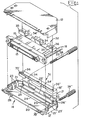
- each half-shell 12 comprises a base wall 20, side walls 21 and 21' upstanding from opposite edges of the base wall and rear wall 22 joining the side walls at the wire receiving face 17.
- Two pairs of fastening eyes 23 and 23' upstand from the base at its junction with the respective side walls, the eyes of one pair 23 being longitudinally staggered from the eyes 23' of the other pair and joined by a strengthening rib 24 which extend in parallel relation across the base wall adjacent the rear wall and a pair of locating posts 26 and 26' upstand in spaced apart relation from the base wall between the channels 25 and 25'.
- the rear wall is formed with spaced-apart knock-outs 27 and 27' removable to provide bundle receiving apertures when the housing shells are assembled together.
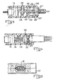
- the conductor locating members 18 comprise first and second, opposite, flat cable and conductor bundle locating faces 31, 32.
- the first face is formed with a rib 33 along a first edge having a canted edge to define a hook.
- the second face is formed with a pair of spaced bundle receiving openings 34, 34' and a step 35 extending between the openings along a second edge of the second face spaced longitudinally (in the direction of the cable) from the rib 33.
- a pair of through sockets 36, 36' extend in spaced relation through the members.
- the terminal block In assembling the connector to the fiat cable 15, the terminal block is located in a half-shell adjacent the mating face 14 and the cable extending over a first face of cable locating member located in the half-shell by the posts 26, 26' being freely received in the sockets 36, 36'.
- the other half-shell is then assembled to the first with the other cable locating member similarly mounted on the posts, and the half-shells assembled together, eye pairs 23 of one shell interdigitating with eye pairs 23' of the other half-shell to that jackscrews 38, 38' can be threaded in locking engagement through both pairs on each side of the housing and secured by circlips as shown in Figure 3.
- the steps 35, 35' are received in respective channels and the post 26, 26' received in respective sockets.
- the connector is particularly adapted to mate with an upstanding printed circuit board post header formed with an elongate keyway for receiving a polarising key in a preselected longitudinal position corresponding with the location of a removed tooth.
Landscapes
- Coupling Device And Connection With Printed Circuit (AREA)
- Details Of Connecting Devices For Male And Female Coupling (AREA)
- Multi-Conductor Connections (AREA)
Applications Claiming Priority (2)
| Application Number | Priority Date | Filing Date | Title |
|---|---|---|---|
| US59135284A | 1984-03-19 | 1984-03-19 | |
| US591352 | 2006-11-01 |
Publications (2)
| Publication Number | Publication Date |
|---|---|
| EP0159115A1 true EP0159115A1 (fr) | 1985-10-23 |
| EP0159115B1 EP0159115B1 (fr) | 1988-06-01 |
Family
ID=24366153
Family Applications (1)
| Application Number | Title | Priority Date | Filing Date |
|---|---|---|---|
| EP85301232A Expired EP0159115B1 (fr) | 1984-03-19 | 1985-02-25 | Connecteur électrique pour câble plat ou faisceaux de fils |
Country Status (5)
| Country | Link |
|---|---|
| EP (1) | EP0159115B1 (fr) |
| JP (1) | JPH0746620B2 (fr) |
| BR (1) | BR8501157A (fr) |
| DE (1) | DE3563155D1 (fr) |
| ES (1) | ES8702744A1 (fr) |
Cited By (4)
| Publication number | Priority date | Publication date | Assignee | Title |
|---|---|---|---|---|
| EP0531554A1 (fr) * | 1991-09-06 | 1993-03-17 | Siemens Aktiengesellschaft | Transformateur, par exemple transformateur différentiel |
| FR2683683A1 (fr) * | 1991-11-13 | 1993-05-14 | Legrand Sa | Serre-cable et appareil electrique equipe d'un tel serre-cable. |
| AU675528B2 (en) * | 1994-06-06 | 1997-02-06 | Krone Gmbh | Test plug |
| FR2765037A1 (fr) * | 1997-06-24 | 1998-12-24 | Cinch Connecteurs Sa | Element de boitier d'un connecteur electrique |
Families Citing this family (2)
| Publication number | Priority date | Publication date | Assignee | Title |
|---|---|---|---|---|
| JP2020192952A (ja) | 2019-05-30 | 2020-12-03 | ヤマハ発動機株式会社 | インホイールモータユニット及び電動車両 |
| JP2020192951A (ja) | 2019-05-30 | 2020-12-03 | ヤマハ発動機株式会社 | インホイールモータユニット及び電動車両 |
Citations (9)
| Publication number | Priority date | Publication date | Assignee | Title |
|---|---|---|---|---|
| DE1127429B (de) * | 1960-02-04 | 1962-04-12 | Siemens Ag | Anordnung zur Zugentlastung fuer biegsame, im Gehaeuse elektrischer Geraete eingefuehrte Anschlussleitungen |
| DE2146976A1 (de) * | 1971-09-21 | 1973-03-22 | Werner Kunert | Steckvorrichtung elektrischer zuleitungen |
| US3856376A (en) * | 1970-04-20 | 1974-12-24 | Leviton Manufacturing Co | Electrical connector |
| US3994555A (en) * | 1974-03-04 | 1976-11-30 | Bunker Ramo Corporation | Connector casing |
| US4108527A (en) * | 1977-06-23 | 1978-08-22 | Amp Incorporated | Strain relief assembly |
| DE3046062A1 (de) * | 1980-12-06 | 1982-06-09 | Rafi Gmbh & Co Elektrotechnische Spezialfabrik, 7981 Berg | Steckergehaeuse |
| EP0059566A1 (fr) * | 1981-03-02 | 1982-09-08 | AMP INCORPORATED (a New Jersey corporation) | Assemblage d'enveloppe à deux voies |
| EP0080295A1 (fr) * | 1981-11-20 | 1983-06-01 | AMP INCORPORATED (a New Jersey corporation) | Assemblage de câble coaxial ruban blindé |
| FR2520945A1 (fr) * | 1982-01-29 | 1983-08-05 | Essilor Int | Dispositif de fixation de cable d'alimentation ou de sortie |
-
1985
- 1985-02-25 EP EP85301232A patent/EP0159115B1/fr not_active Expired
- 1985-02-25 DE DE8585301232T patent/DE3563155D1/de not_active Expired
- 1985-03-15 BR BR8501157A patent/BR8501157A/pt not_active IP Right Cessation
- 1985-03-18 ES ES541355A patent/ES8702744A1/es not_active Expired
- 1985-03-19 JP JP60055637A patent/JPH0746620B2/ja not_active Expired - Lifetime
Patent Citations (9)
| Publication number | Priority date | Publication date | Assignee | Title |
|---|---|---|---|---|
| DE1127429B (de) * | 1960-02-04 | 1962-04-12 | Siemens Ag | Anordnung zur Zugentlastung fuer biegsame, im Gehaeuse elektrischer Geraete eingefuehrte Anschlussleitungen |
| US3856376A (en) * | 1970-04-20 | 1974-12-24 | Leviton Manufacturing Co | Electrical connector |
| DE2146976A1 (de) * | 1971-09-21 | 1973-03-22 | Werner Kunert | Steckvorrichtung elektrischer zuleitungen |
| US3994555A (en) * | 1974-03-04 | 1976-11-30 | Bunker Ramo Corporation | Connector casing |
| US4108527A (en) * | 1977-06-23 | 1978-08-22 | Amp Incorporated | Strain relief assembly |
| DE3046062A1 (de) * | 1980-12-06 | 1982-06-09 | Rafi Gmbh & Co Elektrotechnische Spezialfabrik, 7981 Berg | Steckergehaeuse |
| EP0059566A1 (fr) * | 1981-03-02 | 1982-09-08 | AMP INCORPORATED (a New Jersey corporation) | Assemblage d'enveloppe à deux voies |
| EP0080295A1 (fr) * | 1981-11-20 | 1983-06-01 | AMP INCORPORATED (a New Jersey corporation) | Assemblage de câble coaxial ruban blindé |
| FR2520945A1 (fr) * | 1982-01-29 | 1983-08-05 | Essilor Int | Dispositif de fixation de cable d'alimentation ou de sortie |
Non-Patent Citations (1)
| Title |
|---|
| IBM TECHNICAL DISCLOSURE BULLETIN, vol. 25, no. 10, March 1983, pages 5374-5375, New York, US; P.G. BURNS et al.: "Double locking clamp for flat cable applications" * |
Cited By (4)
| Publication number | Priority date | Publication date | Assignee | Title |
|---|---|---|---|---|
| EP0531554A1 (fr) * | 1991-09-06 | 1993-03-17 | Siemens Aktiengesellschaft | Transformateur, par exemple transformateur différentiel |
| FR2683683A1 (fr) * | 1991-11-13 | 1993-05-14 | Legrand Sa | Serre-cable et appareil electrique equipe d'un tel serre-cable. |
| AU675528B2 (en) * | 1994-06-06 | 1997-02-06 | Krone Gmbh | Test plug |
| FR2765037A1 (fr) * | 1997-06-24 | 1998-12-24 | Cinch Connecteurs Sa | Element de boitier d'un connecteur electrique |
Also Published As
| Publication number | Publication date |
|---|---|
| ES8702744A1 (es) | 1986-12-16 |
| JPH0746620B2 (ja) | 1995-05-17 |
| EP0159115B1 (fr) | 1988-06-01 |
| JPS60212981A (ja) | 1985-10-25 |
| DE3563155D1 (en) | 1988-07-07 |
| BR8501157A (pt) | 1985-11-12 |
| ES541355A0 (es) | 1986-12-16 |
Similar Documents
| Publication | Publication Date | Title |
|---|---|---|
| CA1089200A (fr) | Serre-cable | |
| US4244638A (en) | Snap-in strain relief | |
| EP0632541B1 (fr) | Connecteur électrique pour câble plat à haute densité | |
| US4653825A (en) | Shielded electrical connector assembly | |
| US4035051A (en) | Adjustable molded hood assembly for a cable connector plug | |
| US4448471A (en) | Polarized locking latch cover for an electrical connector | |
| US7004795B2 (en) | Powerpole connector assembly and methods thereof | |
| EP0017330A1 (fr) | Bloc de connexion à cloisons pour l'interconnexion de fils électriques | |
| EP0390450A1 (fr) | Connecteur empilable dos à dos pour bus d'interface | |
| US4367005A (en) | Strain relief cover | |
| JPH0330263A (ja) | ワイヤ接続装置 | |
| EP0080813A1 (fr) | Enveloppe en forme de coquille arrière hermaphrodite | |
| US6126478A (en) | Wiring device with gripping of individual conductors | |
| US4456317A (en) | Commoning strip | |
| US4431249A (en) | Male/female cable connector | |
| US4341431A (en) | Strain relief | |
| EP0159115B1 (fr) | Connecteur électrique pour câble plat ou faisceaux de fils | |
| US4592614A (en) | Gender change connector | |
| NO772841L (no) | Elektrisk kontaktanordning. | |
| US5653609A (en) | Strain relief for an electrical connector | |
| US5133674A (en) | Flat ribbon cable strain relief fitting | |
| US4734056A (en) | Electrical connector for flat cable or wire bundles | |
| US4369944A (en) | Universal strand clamp and strand clamp assembly | |
| EP0021785B1 (fr) | Assemblage de connecteurs électriques à connecteurs mâle et femelle serrés ensemble | |
| GB1572551A (en) | Electrical connector assemblies |
Legal Events
| Date | Code | Title | Description |
|---|---|---|---|
| PUAI | Public reference made under article 153(3) epc to a published international application that has entered the european phase |
Free format text: ORIGINAL CODE: 0009012 |
|
| AK | Designated contracting states |
Designated state(s): BE DE FR GB IT NL |
|
| 17P | Request for examination filed |
Effective date: 19860221 |
|
| 17Q | First examination report despatched |
Effective date: 19861007 |
|
| ITF | It: translation for a ep patent filed | ||
| GRAA | (expected) grant |
Free format text: ORIGINAL CODE: 0009210 |
|
| AK | Designated contracting states |
Kind code of ref document: B1 Designated state(s): BE DE FR GB IT NL |
|
| PG25 | Lapsed in a contracting state [announced via postgrant information from national office to epo] |
Ref country code: NL Effective date: 19880601 Ref country code: BE Effective date: 19880601 |
|
| REF | Corresponds to: |
Ref document number: 3563155 Country of ref document: DE Date of ref document: 19880707 |
|
| ET | Fr: translation filed | ||
| NLV1 | Nl: lapsed or annulled due to failure to fulfill the requirements of art. 29p and 29m of the patents act | ||
| PLBE | No opposition filed within time limit |
Free format text: ORIGINAL CODE: 0009261 |
|
| STAA | Information on the status of an ep patent application or granted ep patent |
Free format text: STATUS: NO OPPOSITION FILED WITHIN TIME LIMIT |
|
| 26N | No opposition filed | ||
| ITTA | It: last paid annual fee | ||
| REG | Reference to a national code |
Ref country code: GB Ref legal event code: 732E |
|
| PGFP | Annual fee paid to national office [announced via postgrant information from national office to epo] |
Ref country code: GB Payment date: 19950110 Year of fee payment: 11 |
|
| PGFP | Annual fee paid to national office [announced via postgrant information from national office to epo] |
Ref country code: FR Payment date: 19950214 Year of fee payment: 11 |
|
| PG25 | Lapsed in a contracting state [announced via postgrant information from national office to epo] |
Ref country code: GB Effective date: 19960225 |
|
| GBPC | Gb: european patent ceased through non-payment of renewal fee |
Effective date: 19960225 |
|
| PG25 | Lapsed in a contracting state [announced via postgrant information from national office to epo] |
Ref country code: FR Effective date: 19961031 |
|
| REG | Reference to a national code |
Ref country code: FR Ref legal event code: ST |
|
| PGFP | Annual fee paid to national office [announced via postgrant information from national office to epo] |
Ref country code: DE Payment date: 19970224 Year of fee payment: 13 |
|
| PG25 | Lapsed in a contracting state [announced via postgrant information from national office to epo] |
Ref country code: DE Free format text: LAPSE BECAUSE OF NON-PAYMENT OF DUE FEES Effective date: 19981103 |