EP0159151A1 - Appareil à bourrer des matières pâteuses - Google Patents
Appareil à bourrer des matières pâteuses Download PDFInfo
- Publication number
- EP0159151A1 EP0159151A1 EP85302017A EP85302017A EP0159151A1 EP 0159151 A1 EP0159151 A1 EP 0159151A1 EP 85302017 A EP85302017 A EP 85302017A EP 85302017 A EP85302017 A EP 85302017A EP 0159151 A1 EP0159151 A1 EP 0159151A1
- Authority
- EP
- European Patent Office
- Prior art keywords
- piston
- sleeve
- plunger
- rod
- retracted
- Prior art date
- Legal status (The legal status is an assumption and is not a legal conclusion. Google has not performed a legal analysis and makes no representation as to the accuracy of the status listed.)
- Withdrawn
Links
- 238000005086 pumping Methods 0.000 title claims abstract description 13
- 239000000463 material Substances 0.000 title claims description 14
- 239000004033 plastic Substances 0.000 title claims description 9
- 229920003023 plastic Polymers 0.000 title claims description 9
- 239000012530 fluid Substances 0.000 claims abstract description 24
- 230000000712 assembly Effects 0.000 claims abstract description 10
- 238000000429 assembly Methods 0.000 claims abstract description 10
- 235000013305 food Nutrition 0.000 claims description 15
- 235000013580 sausages Nutrition 0.000 claims description 4
- 235000013372 meat Nutrition 0.000 claims description 3
- 235000015277 pork Nutrition 0.000 claims description 3
- 230000004044 response Effects 0.000 claims description 2
- 239000000969 carrier Substances 0.000 claims 2
- 230000007246 mechanism Effects 0.000 description 5
- 238000004519 manufacturing process Methods 0.000 description 4
- 238000010276 construction Methods 0.000 description 3
- 229910001220 stainless steel Inorganic materials 0.000 description 3
- 239000010935 stainless steel Substances 0.000 description 3
- 239000004677 Nylon Substances 0.000 description 2
- 230000009471 action Effects 0.000 description 2
- 238000005520 cutting process Methods 0.000 description 2
- 229920001778 nylon Polymers 0.000 description 2
- 239000002245 particle Substances 0.000 description 2
- 239000007787 solid Substances 0.000 description 2
- 230000000295 complement effect Effects 0.000 description 1
- 230000008878 coupling Effects 0.000 description 1
- 238000010168 coupling process Methods 0.000 description 1
- 238000005859 coupling reaction Methods 0.000 description 1
- 230000006378 damage Effects 0.000 description 1
- 238000012423 maintenance Methods 0.000 description 1
- 238000000034 method Methods 0.000 description 1
- 230000002093 peripheral effect Effects 0.000 description 1
- 230000008569 process Effects 0.000 description 1
- MFOUDYKPLGXPGO-UHFFFAOYSA-N propachlor Chemical compound ClCC(=O)N(C(C)C)C1=CC=CC=C1 MFOUDYKPLGXPGO-UHFFFAOYSA-N 0.000 description 1
- 230000001105 regulatory effect Effects 0.000 description 1
- 238000007789 sealing Methods 0.000 description 1
- 238000003466 welding Methods 0.000 description 1
Images


Classifications
-
- A—HUMAN NECESSITIES
- A22—BUTCHERING; MEAT TREATMENT; PROCESSING POULTRY OR FISH
- A22C—PROCESSING MEAT, POULTRY, OR FISH
- A22C11/00—Sausage making ; Apparatus for handling or conveying sausage products during manufacture
- A22C11/02—Sausage filling or stuffing machines
- A22C11/06—Sausage filling or stuffing machines with piston operated by liquid or gaseous means
-
- F—MECHANICAL ENGINEERING; LIGHTING; HEATING; WEAPONS; BLASTING
- F15—FLUID-PRESSURE ACTUATORS; HYDRAULICS OR PNEUMATICS IN GENERAL
- F15B—SYSTEMS ACTING BY MEANS OF FLUIDS IN GENERAL; FLUID-PRESSURE ACTUATORS, e.g. SERVOMOTORS; DETAILS OF FLUID-PRESSURE SYSTEMS, NOT OTHERWISE PROVIDED FOR
- F15B15/00—Fluid-actuated devices for displacing a member from one position to another; Gearing associated therewith
- F15B15/08—Characterised by the construction of the motor unit
- F15B15/14—Characterised by the construction of the motor unit of the straight-cylinder type
- F15B15/1409—Characterised by the construction of the motor unit of the straight-cylinder type with two or more independently movable working pistons
Definitions
- This invention relates to apparatus for pumping plastics materials such as edible food products, typically pork or other sausage meat, in a machine for producing edible products, the apparatus being of the kind comprising a pair of plungers which are alternately reciprocable to discharge into a common conduit, and each plunger operates in conjunction with a sleeve in which it is adapted to work and which, in turn, is adapted to reciprocate into and out of a loading area which has been filled with the product, the apparatus being so constructed and arranged that when a sleeve moves through the product from a retracted into an operative advanced position in which it seals against an end wall surrounding an opening leading to the conduit, a loaded pumping chamber is thereby effectively defined through which the plunger can be advanced to force the confined product into the conduit.
- Apparatus of this kind will hereinafter be referred to as apparatus of the kind set forth.
- plastics materials' is intended to include those food materials which are too dry to pump by suction and unsuitable for moving by means of a screw or auger owing to the distance involved.
- the automatic sausage stuffing machine dislcosed in U.S. 3 108 318 utilises a single hydraulic power unit for reciprocating the plunger and sleeve of each assembly but in this known arrangement the ram of the power unit is operatively connected by a very complicated linkage mechanism to both plunger and sleeve. Trip switches are operated by the linkage parts to achieve alternate extension and retraction of the pairs of cutting sleeves and feed plungers.
- each sleeve is operated by a pair of ram rods and each plunger by a single ram rod.
- the sleeves carry further rods for operating trip switches.
- the ram rods for the plungers carry further rods for switching purposes. Again the arrangement is complicated which is always a drawback from the point of view of cost and operating efficiency.
- each plunger and sleeve assembly is actuated by an hydraulic actuator assembly, and each actuator assembly comprises inner and outer co-axial pistons of which the outer piston is adapted to reciprocate the sleeve between its retracted and advanced positions and the inner piston is adapted to reciprocate the plunger in the bore of the sleeve between its retracted and advanced positions.
- each of the two actuator assemblies may comprise a self-contained unit for co-operation with a respective plunger and sleeve assembly.
- Each self contained unit may comprise an hydraulic pump controlled by a common control circuit.
- the units are mounted side-by-side on a frame on which the apparatus of the kind set forth is also mounted.
- the frame may be mounted on wheels or skids for mobility in use.
- the outer piston and the inner piston work in respective portions of greater and smaller diameters of a common bore in a housing
- the outer piston carries a first piston-rod which works through a seal in a closure for the outer end of the portion of greater diameter for co-operation with the sleeve
- the inner piston carries a second piston-rod which projects through a common axial through-bore in the outer piston and the first piston-rod for co-operation with the plunger, a seal being provided between the through-bore and the second piston-rod, and an abutment being provided between the outer piston and a shoulder on the second piston-rod to retract the plunger with the sleeve as the sleeve is retracted from its advanced position into its retracted position.
- the housing may comprise two tubular sections having different bore diameters which are rigidly connected together by a common end fitting.
- said second piston-rod may comprise two rod-parts joined end-to-end by a spigot and socket connection, and said shoulder may be provided by a separate spacing member mounted on the spigot.
- each actuator assembly is operated by supplying fluid in sequence to each of three ports in the wall of the housing of which first and second ports are disposed at opposite ends of the housing for supplying fluid under pressure to the outer end of the outer piston and to the outer end of the inner piston, respectively, and the third port is disposed at an intermediate point in the length of the housing to supply pressure simultaneously to opposed ends of the two pistons, the sequence of fluid supply being as follows:-
- At least one of the above-mentioned ports may be provided in a separate end fitting connected to the tubular housing section.
- the sequence described above is controlled by solenoid-operated hydraulic controlled valves which are operated in sequence in response to signals from a micro-switch responsive to the positions of the two sleeves, and the pressure acting on the inner piston when that piston is in its fully advanced position.
- the apparatus illustrated in the drawings comprises a wheel mounted elongate frame 1 of skeletal outline on which is mounted an open-topped stainless steel cabinet 2 of generally rectangular section which receives food products through a hopper 3 into a loading area defined by the interior 2a of the cabinet.
- the outer end wall 4 of the cabinet has a pair of discharge conduits 5,6 which discharge into a common manifold 7 having a single outlet conduit 8.
- a suitable flapper valve (not shown) housed within the manifold 7 opens and closes the two conduits 5 and 6 alternately such that food products discharged through one conduit cannot be pumped back into the other conduit.
- a pair of transversely spaced, stainless steel, cylindrical sleeves 9 and 10 are alternately reciprocal between the opposite end walls 4, 11 of the cabinet 2 between a retracted position in which their inner ends, that is the ends which extend into the cabinet, are substantially in alignment with a face of the inner end wall 11 and an advanced operative position in which the inner ends seat against seatings 12,13 of nylon or similar plastics material surrounding the inner ends of the respective conduits 5,6.
- each sleeve 9,10 moves through the food product disposed in the loading area of the cabinet so that its bore which defines a pumping chamber 14 is filled with the food product from the loading area.
- a feed plunger 15, of suitable plastics material, working in the bore of each sleeve 9, 10 is movable between a retracted position in which its inner end, that is the operative end which contacts the food material, is substantially aligned with the position assumed by the outer end of the respective sleeve 9,10 when the sleeve is in its advanced position, and an advanced position to force the confined product from the pumping chamber 14 and into the respective conduit 5,6.
- each sleeve 9,10 and its respective plunger 15 is controlled by an hydraulic actuator assembly 16,17, and the two assemblies 16 and 17, are mounted on the frame by means of a support member 69 and a yoke plate 70, to the rear of the cabinet 2, with their axes in a spaced parallel relationship.
- a pair of guide bushes 71 of plastics material are clamped between the plate 70 and the end wall 11 of the cabinet 2. These slidingly support the inner ends of the sleeves 9, 10.
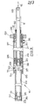
- the two actuator assemblies 16,17 are identical in construction and one assembly 16 is shown in detail in Figure 3.
- Each assembly 16,17 comprises a cylindrical housing 20 having an internal longitudinally extending bore of stepped outline of which a bore portion 21 of greater diameter is located adjacent to the cabinet 2, and a bore portion 22 of smaller diameter is closed at its outer end remote from the cabinet 2 by means of a plug 23.
- the plug comprises an inlet port 36 for hydraulic fluid and a bleed point 60.
- An end part of the plug within the bore portion 22 is formed as an annular abutment 61 for a piston 25 carried on one end of a two-part piston rod 29.
- the rod 29 also slidingly supports a coaxial piston 26 with its tubular rod 27.
- the two-part piston rod 29 is made up from two rod parts of substantially equal diameter one of which is formed with a screw threaded cylindrical end spigot 66 and the other with a complementary screw threaded bore providing a screwed connection for the two rod parts.
- An annular spacing member 38 is mounted on the spigot 66 trapped between the two co-axially joined parts. In operation the spacing member provides an abutment for the piston 26 and also allows the inner face of the piston 26 to be exposed to fluid pressure to drive the piston in one direction, as will be described below.
- the two pistons 25, 26, are secured to the ends of respective piston rods 29, 27 by any suitable means such as screw threads or welding.
- the inner piston 25 is single acting and the outer piston 26 double acting.
- the two pistons work in the bore portions 22 and 21 respectively.
- the tubular piston rod 27 of the outer piston 26 works through a sealing closure 28 for the outer end of the bore portion 21 and is coupled at its free end to a respective one of the sleeves 9,10 as indicated by the double headed arrow 9.
- the two-part piston rod 29 of the inner piston 25 is of substantial length and projects from the housing 20 through a common open-ended longitudinal bore 30 passing through the outer piston 26 and the piston-rod 27 and works through axially spaced seals 31,32 at the free end of the piston rod 27.
- the free end 68 of the piston rod 29 is coupled to the plunger 15 which works in the bore of the sleeve 9,10 as indicated by the double headed arrow 15.
- the end of piston-rod 27 is coupled to the sleeve 9, 10 by means of a releasable coupling (not shown) achieved through radial lugs or an annular flange on the end of the sleeve.
- the free end 68 of the piston rod 29 is releasably coupled to the plunger 15 by means of a pin and socket arrangement (not shown).
- the housing 20 is made up from two tube portions of different diameters.
- the tube portion 21 of larger diameter is welded to a tubular end fitting 62 which comprises an inlet port 37 for hydraulic fluid and a bleed point 63.
- the tube portion 22 is secured co-axially in a recess in the end fitting 62 by means of a retaining flange 64 welded to the tube adjacent to its inner end and screw means 65.
- a seal 70 is provided between the end of tube portion 22 and the end fitting 62.
- the housing 20 is provided with three radial inlet ports 35,36 and 37 of which the ports 35 and 36 are provided at the opposite end of the housing 20 to admit hydraulic fluid under pressure into the two respective bore portions 21 and 22 adjacent to their outer ends, and the third port 37 is positioned between opposed ends of the two pistons 25,26, irrespective of the relative positions of the two pistons 25,26 in the bore portions 22,21.
- the two actuator assemblies 16,17 are alternately actuated in a predetermined sequence, and each assembly operates as follows. Beginning with the components in the retracted positions shown in Figure 3 and 4 and the sleeve 9,10 and the plunger 15 in equivalent retracted positions, fluid under pressure is first applied to the port 37. This acts simultaneously on the opposed faces of the two pistons 25, 26 to hold the inner piston 25 in its retracted position and advance the outer piston 26 in the bore portion 21, in turn to urge sleeve 9,10 through the food product in the loading area 2a of the cabinet 2 and into its advanced position in contact with the seating 12, 13 to define the pumping chamber 14 as described above.
- the pressure applied to the third port 37 is then cut-off and pressure is applied to the port 36 which acts on the inner piston 25 to urge the piston rod 29 together with its respective plunger 15 into their advanced positions with the plunger 15 displacing the product from the pumping chamber 14, through the conduit 5,6 and the manifold 7 into the conduit 8.
- the spacing member 38 is substantially in abutment with the piston 26 at the cabinet end of the bore portion 21.
- the pressure applied to the port 36 is cut-off and fluid pressure is then applied to the port 35 which acts on the outer end of the piston 26 to return that piston to its retracted position accompanied by an equivalent movement of the inner piston 25 due to the engagement of the piston 26 with the spacing member 38 on the piston rod 29.
- a master electrical switch (not shown) is operated to energise the control circuit and the solenoid-operated valve 42 is then operative to supply fluid to the port 37 of the actuator assembly 16 with the solenoid-operated valve 44 operative to supply fluid to the port 35 of the other actuator assembly 17.
- the sleeve 9 engages with its seating 12 in the end wall 4 of the chamber 2 at the end of its stroke it is also operative to actuate a micro-switch (not shown).
- This sends an electrical signal to the two solenoid-operated valves 41 and 42 to cut-off the supply to the port 37 and apply fluid to the port 36 of the actuator assembly 16, and to the two solenoid-operated valves 43,44 to cut-off the supply of fluid to the port 35 of the actuator assembly 17 and apply fluid to the port 37 in order to urge the sleeve 10 towards its advanced position.
- a similar sequence is applied to the actuator assembly 17 with a micro-switch operated by the sleeve 10 in its advanced position.
- the micro-switch is operative to energise the solenoid-operated valves 43,44 in sequence in order the advance the plunger 15 controlled by the piston 25 until a pressure switch 51 responsive to pressure applied to the piston 25 is operative to act in a similar manner to the pressure switch 50.
- the apparatus described above can be used in any particular role in the manufacture of edible products. For example, it could be used to measure the quantity of food material supplied to a machine in an automated process.
- the primary use of the apparatus is as a pump to elevate food products from a level close to the ground to the substantial height of a hopper of a depositor in a meat-pie making apparatus. This facilitates the manufacturing process and assists the operator considerably in loading the depositor with food stuffs.
- the pump described above is particularly suitable for use with pork or other sausage meat since relatively solid particles can be transferred from a lower level to a higher level substantially without destruction or immulsification of the solid particles.
- each actuator assembly functions as a self contained unit and is supplied by a separate hydraulic pump in order to ensure that sufficient power in available whatever the consistency of the plastics food material being pumped, or alternatively twin pumps may be linked into a common hydraulic circuit.
- the feed plungers are of plastics material such as nylon and the sleeves of stainless steel. It will be appreciated that this combination of materials could be reversed, if desired, or both parts could be of the same material.
Landscapes
- Engineering & Computer Science (AREA)
- Life Sciences & Earth Sciences (AREA)
- Physics & Mathematics (AREA)
- Fluid Mechanics (AREA)
- Mechanical Engineering (AREA)
- General Engineering & Computer Science (AREA)
- Wood Science & Technology (AREA)
- Zoology (AREA)
- Food Science & Technology (AREA)
- Reciprocating Pumps (AREA)
Applications Claiming Priority (2)
| Application Number | Priority Date | Filing Date | Title |
|---|---|---|---|
| GB8407717 | 1984-03-24 | ||
| GB848407717A GB8407717D0 (en) | 1984-03-24 | 1984-03-24 | Pumping plastics materials |
Publications (1)
| Publication Number | Publication Date |
|---|---|
| EP0159151A1 true EP0159151A1 (fr) | 1985-10-23 |
Family
ID=10558647
Family Applications (1)
| Application Number | Title | Priority Date | Filing Date |
|---|---|---|---|
| EP85302017A Withdrawn EP0159151A1 (fr) | 1984-03-24 | 1985-03-22 | Appareil à bourrer des matières pâteuses |
Country Status (2)
| Country | Link |
|---|---|
| EP (1) | EP0159151A1 (fr) |
| GB (2) | GB8407717D0 (fr) |
Cited By (4)
| Publication number | Priority date | Publication date | Assignee | Title |
|---|---|---|---|---|
| AU580196B2 (en) * | 1986-08-15 | 1989-01-05 | Steaka - Maka Marketing Pty. Limited | A food compressor |
| EP0362965A1 (fr) * | 1988-10-05 | 1990-04-11 | Stork Protecon B.V. | Appareil à bourrer des produits contenant de la viande |
| EP0443148A1 (fr) * | 1990-02-09 | 1991-08-28 | Robert Bosch Gmbh | Capteur de position |
| IT201700010739A1 (it) * | 2017-02-01 | 2018-08-01 | Roc S R L | Cilindro idraulico e gruppo di sollevamento per una macchina agricola |
Families Citing this family (1)
| Publication number | Priority date | Publication date | Assignee | Title |
|---|---|---|---|---|
| US4700899A (en) * | 1985-10-18 | 1987-10-20 | Marlen Research Corporation | Continuous vacuum grinding method and apparatus |
Citations (7)
| Publication number | Priority date | Publication date | Assignee | Title |
|---|---|---|---|---|
| FR1124969A (fr) * | 1954-03-23 | 1956-10-22 | Rolls Royce | Perfectionnements aux vérins |
| GB911709A (en) * | 1960-04-25 | 1962-11-28 | Automotive Prod Co Ltd | Improvements in and relating to hydraulic cylinders |
| US3108318A (en) * | 1960-03-11 | 1963-10-29 | Marlen Equipment Company | Machine for stuffing sausage and similar casings |
| US3456285A (en) * | 1967-06-05 | 1969-07-22 | Marlen Equipment Co | Continuous hydraulic stuffer |
| DE2701322B1 (de) * | 1977-01-14 | 1978-04-13 | Fa. Walter Dingler, 7414 Lichtenstein | Hydraulische Kolben-Zylindeveinheit |
| US4097962A (en) * | 1976-07-26 | 1978-07-04 | Marlen Research Corporation | Machine for continuous pumping of plastic materials |
| GB2075459A (en) * | 1980-04-23 | 1981-11-18 | Union Carbide Corp | Stuffing a pliable article into a casing |
-
1984
- 1984-03-24 GB GB848407717A patent/GB8407717D0/en active Pending
-
1985
- 1985-03-21 GB GB08507332A patent/GB2156444B/en not_active Expired
- 1985-03-22 EP EP85302017A patent/EP0159151A1/fr not_active Withdrawn
Patent Citations (7)
| Publication number | Priority date | Publication date | Assignee | Title |
|---|---|---|---|---|
| FR1124969A (fr) * | 1954-03-23 | 1956-10-22 | Rolls Royce | Perfectionnements aux vérins |
| US3108318A (en) * | 1960-03-11 | 1963-10-29 | Marlen Equipment Company | Machine for stuffing sausage and similar casings |
| GB911709A (en) * | 1960-04-25 | 1962-11-28 | Automotive Prod Co Ltd | Improvements in and relating to hydraulic cylinders |
| US3456285A (en) * | 1967-06-05 | 1969-07-22 | Marlen Equipment Co | Continuous hydraulic stuffer |
| US4097962A (en) * | 1976-07-26 | 1978-07-04 | Marlen Research Corporation | Machine for continuous pumping of plastic materials |
| DE2701322B1 (de) * | 1977-01-14 | 1978-04-13 | Fa. Walter Dingler, 7414 Lichtenstein | Hydraulische Kolben-Zylindeveinheit |
| GB2075459A (en) * | 1980-04-23 | 1981-11-18 | Union Carbide Corp | Stuffing a pliable article into a casing |
Cited By (5)
| Publication number | Priority date | Publication date | Assignee | Title |
|---|---|---|---|---|
| AU580196B2 (en) * | 1986-08-15 | 1989-01-05 | Steaka - Maka Marketing Pty. Limited | A food compressor |
| US4885822A (en) * | 1986-08-15 | 1989-12-12 | Steaka-Maka Marketing Pty Limited | Food compressor |
| EP0362965A1 (fr) * | 1988-10-05 | 1990-04-11 | Stork Protecon B.V. | Appareil à bourrer des produits contenant de la viande |
| EP0443148A1 (fr) * | 1990-02-09 | 1991-08-28 | Robert Bosch Gmbh | Capteur de position |
| IT201700010739A1 (it) * | 2017-02-01 | 2018-08-01 | Roc S R L | Cilindro idraulico e gruppo di sollevamento per una macchina agricola |
Also Published As
| Publication number | Publication date |
|---|---|
| GB2156444B (en) | 1987-06-17 |
| GB2156444A (en) | 1985-10-09 |
| GB8407717D0 (en) | 1984-05-02 |
| GB8507332D0 (en) | 1985-05-01 |
Similar Documents
| Publication | Publication Date | Title |
|---|---|---|
| US4036124A (en) | Sludge press | |
| US5655436A (en) | Food patty molding machine | |
| GB2360804A (en) | Blowout Preventer Ram Actuating Mechanism | |
| US4241641A (en) | Pilot assembly for hydraulic pumps | |
| JPH0417611B2 (fr) | ||
| GB2156444A (en) | Apparatus for pumping plastics materials | |
| US4479758A (en) | Piston filler | |
| EP0118497A4 (fr) | Pompe de forage et de puits a actionnement hydraulique. | |
| US3830139A (en) | Pneumatic actuator | |
| CA1301546C (fr) | Pomoe a deux pistons de faibles dimension | |
| DE1964076C3 (de) | Arbeitszylinder mit Eilgang und Krafthub | |
| US2111915A (en) | Batch-measuring device for feeding materials to curb presses | |
| US3473189A (en) | Multi-channel stuffing system | |
| US5735140A (en) | Method and apparatus for producing high density dry ice | |
| US6986303B2 (en) | Displacement shift valve and pumping apparatus and methods using such a valve | |
| CN219711921U (zh) | 一种多个多级液压缸同步驱动的液压装置 | |
| DE3525003A1 (de) | Verfahren und vorrichtung zum foerdern von beton aus einem behaelter in eine lieferleitung | |
| EP0213709A1 (fr) | Dispositif de distribution de produits alimentaires | |
| CA2170655C (fr) | Dispositif de compactage hydraulique a double action | |
| DE3504107C2 (fr) | ||
| US4456438A (en) | Extrusion device for impregnating a rock formation, preferably for bonding with a liquid synthetic product | |
| US5465646A (en) | Hydraulic motor | |
| CN108726201B (zh) | 禽类生肉全液压智能自动输送设备 | |
| DE3911278C2 (de) | Plunger-Pumpe | |
| RU2219427C2 (ru) | Нагнетатель для автоматической подачи уплотнительного и смазывающего материала |
Legal Events
| Date | Code | Title | Description |
|---|---|---|---|
| PUAI | Public reference made under article 153(3) epc to a published international application that has entered the european phase |
Free format text: ORIGINAL CODE: 0009012 |
|
| AK | Designated contracting states |
Designated state(s): BE DE FR IT NL |
|
| STAA | Information on the status of an ep patent application or granted ep patent |
Free format text: STATUS: THE APPLICATION IS DEEMED TO BE WITHDRAWN |
|
| 18D | Application deemed to be withdrawn |
Effective date: 19860624 |
|
| RIN1 | Information on inventor provided before grant (corrected) |
Inventor name: SELLEY, BRIAN RICHARD |