EP0159161A1 - Motorsteuervorrichtung für ein hydraulisch angetriebenes Fahrzeug - Google Patents
Motorsteuervorrichtung für ein hydraulisch angetriebenes Fahrzeug Download PDFInfo
- Publication number
- EP0159161A1 EP0159161A1 EP85302272A EP85302272A EP0159161A1 EP 0159161 A1 EP0159161 A1 EP 0159161A1 EP 85302272 A EP85302272 A EP 85302272A EP 85302272 A EP85302272 A EP 85302272A EP 0159161 A1 EP0159161 A1 EP 0159161A1
- Authority
- EP
- European Patent Office
- Prior art keywords
- control lever
- spring
- piston
- engine
- hydraulic
- Prior art date
- Legal status (The legal status is an assumption and is not a legal conclusion. Google has not performed a legal analysis and makes no representation as to the accuracy of the status listed.)
- Granted
Links
Images



Classifications
-
- E—FIXED CONSTRUCTIONS
- E02—HYDRAULIC ENGINEERING; FOUNDATIONS; SOIL SHIFTING
- E02F—DREDGING; SOIL-SHIFTING
- E02F9/00—Component parts of dredgers or soil-shifting machines, not restricted to one of the kinds covered by groups E02F3/00 - E02F7/00
- E02F9/20—Drives; Control devices
- E02F9/22—Hydraulic or pneumatic drives
- E02F9/2246—Control of prime movers, e.g. depending on the hydraulic load of work tools
-
- B—PERFORMING OPERATIONS; TRANSPORTING
- B60—VEHICLES IN GENERAL
- B60K—ARRANGEMENT OR MOUNTING OF PROPULSION UNITS OR OF TRANSMISSIONS IN VEHICLES; ARRANGEMENT OR MOUNTING OF PLURAL DIVERSE PRIME-MOVERS IN VEHICLES; AUXILIARY DRIVES FOR VEHICLES; INSTRUMENTATION OR DASHBOARDS FOR VEHICLES; ARRANGEMENTS IN CONNECTION WITH COOLING, AIR INTAKE, GAS EXHAUST OR FUEL SUPPLY OF PROPULSION UNITS IN VEHICLES
- B60K26/00—Arrangement or mounting of propulsion-unit control devices in vehicles
- B60K26/04—Arrangement or mounting of propulsion-unit control devices in vehicles of means connecting initiating means or elements to propulsion unit
-
- E—FIXED CONSTRUCTIONS
- E02—HYDRAULIC ENGINEERING; FOUNDATIONS; SOIL SHIFTING
- E02F—DREDGING; SOIL-SHIFTING
- E02F9/00—Component parts of dredgers or soil-shifting machines, not restricted to one of the kinds covered by groups E02F3/00 - E02F7/00
- E02F9/20—Drives; Control devices
- E02F9/22—Hydraulic or pneumatic drives
- E02F9/2278—Hydraulic circuits
- E02F9/2292—Systems with two or more pumps
-
- E—FIXED CONSTRUCTIONS
- E02—HYDRAULIC ENGINEERING; FOUNDATIONS; SOIL SHIFTING
- E02F—DREDGING; SOIL-SHIFTING
- E02F9/00—Component parts of dredgers or soil-shifting machines, not restricted to one of the kinds covered by groups E02F3/00 - E02F7/00
- E02F9/20—Drives; Control devices
- E02F9/22—Hydraulic or pneumatic drives
- E02F9/2278—Hydraulic circuits
- E02F9/2296—Systems with a variable displacement pump
-
- F—MECHANICAL ENGINEERING; LIGHTING; HEATING; WEAPONS; BLASTING
- F02—COMBUSTION ENGINES; HOT-GAS OR COMBUSTION-PRODUCT ENGINE PLANTS
- F02D—CONTROLLING COMBUSTION ENGINES
- F02D29/00—Controlling engines, such controlling being peculiar to the devices driven thereby, the devices being other than parts or accessories essential to engine operation, e.g. controlling of engines by signals external thereto
- F02D29/04—Controlling engines, such controlling being peculiar to the devices driven thereby, the devices being other than parts or accessories essential to engine operation, e.g. controlling of engines by signals external thereto peculiar to engines driving pumps
Definitions
- This invention relates to apparatus for controlling the engine of an hydraulically driven vehicle.
- the present invention seeks to obviate these problems encountered previously.
- a transmission mechanism adapted to transmit the operation of a fuel control lever to a governor control lever and having a loose spring mechanism
- a decelerator piston and cylinder device connected to said transmission mechanian; characterised in that: said decelerator cylinder includes a spring having a slightly larger spring force than the loose spring in said loose spring mechanism and adapted to manifest a force absorbing action in the absence of any hydraulic force acting on said piston to set said governor control lever in its deceleration position when said fuel control lever is moved to its full engine speed position, the arrangement being such that said force absorbing action is overcome in the presence of a load acting on said piston to allow said loose spring to move said governor control lever to its full engine speed position; in that an electromagnetic valve is provided for selectively hydraulically connecting and disconnecting a control pump adapted to be driven by the engine to (from)apressure chamber on the head side of said decelerator cylinder; and in that an electric circuit including
- apparatus for controlling the engine of an hydraulically driven vehicle including a transmission mechanism having a loose spring and connecting a fuel control lever operationally to a governor control lever, and a decelerator piston and cylinder device including a piston rod connected to the transmission mechanism by a yoke having a slot, characterised in that: said cylinder includes a spring having a slightly larger spring force than the loose spring and disposed on the opposite side of the piston from an hydraulic fluid chamber; in that an electromagnetic valve is provided for selectively hydraulically connecting and disconnecting an hydraulic pump adapted to be driven by the engine to (from) said hydraulic fluid chamber; and in that an electric circuit is provided for opening or closing the electromagnetic valve.
- apparatus for controlling the engine of an hydraulically driven vehicle characterised in that it includes: a governor control pump separate from the hydraulic work pump circuit for the vehicle such that hydraulic force fluctuation in the hydraulic work circuit due to work operation of the vehicle has no effect on governor control, and an electromagnetic changeover valve responsive electrically to the position of one or more work machine operating levers and adapted to control pressure fluid from the governor control pump for actuation of a deceleration cylinder to effect an automatic control of the governor between its full engine speed position and its idling position.
- a governor control pump separate from the hydraulic work pump circuit for the vehicle such that hydraulic force fluctuation in the hydraulic work circuit due to work operation of the vehicle has no effect on governor control
- an electromagnetic changeover valve responsive electrically to the position of one or more work machine operating levers and adapted to control pressure fluid from the governor control pump for actuation of a deceleration cylinder to effect an automatic control of the governor between its full engine speed position and its idling position.
- the invention also extends to hydraulically driven vehicles provided with such control apparatus.
- Our previously proposed apparatus for controlling the engine of an hydraulically driven vehicle included a pair of hydraulic pumps b and d driven by the engine a for supplying an hydraulic pressure to a travel circuit and a work circuit, respectively and a fuel control lever e which actuates a control lever f for a governor c to thereby set the rotating speed of the engine a.
- the governor control lever f is provided with a drive cylinder g which holds the governor control lever f in an engine idling (or low speed) position when the hydraulic pumps b and d are not under load, and drives it into a full engine speed position when those pumps are loaded.
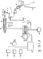
- a governor control lever 2 is provided for an engine 1 mounted in an hydraulically driven vehicles not shown.
- the engine 1 has an output shaft la to which hydraulic pumps 4 and 5 and a control pump 46 are connected.
- An hydraulic pressure is supplied frcm the hydraulic pumps 4 and 5 to a circuit for controlling the swinging operation of the vehicle, a work machine control circuit for controlling the operation of an arm, boom or bucket and a circuit for controlling the travel of the vehicle, which are not shown, through the corresponding operating valves 6, 7 and 47, respectively.
- a fuel control lever 8 has an arm 9 connected by a pin 13 to a rod 12 extending from a spring support 11 in a loose spring mechanism 10.
- the mechanism 10 has a sprirg housing 14 and a rod 15 having one end connected to the spring housing 14 is connected at the other end to a lever 17 having a pair of legs 18 and 20.
- the lever 17 is rotatable about a pivot 16 provided between the legs 18 and 20 and the other end of the rod 15 is connected to the leg 18 by a pin 19.
- the other leg 20 is connected to one end of a push-pull wire 21 and the other end of the wire 21 is connected to one leg 24 of a lever 23.
- the lever 23 has two other legs 25 and 27 and is rotatable about a pivot 22 provided at the junction of the three legs 24, 25 and 27.
- the governor control lever 2 is rotatably connected to the leg 25 by a connecting rod 26.
- the loose spring mechanism 10 and the levers 17 and 23 constitute a transmission mechanism A.
- An intermediate lever 29 has one end which is rotatably connected to the third leg 27 of the , lever 23 by a link 28.
- the lever 29 is rotatable about a pivot 30 provided at its middle point and a pin 31 is provided at the other end of the lever 29.
- the intermediate lever 29 and the parts associated therewith constitute an intermediate connecting mechanism B.
- a decelerator cylinder 32 has a cylindrical housing 33 in which a piston 34 is provided.
- a piston rod 35 connected to the piston 34 extends outwardly through a closure member 36 at one end of the housing 33 and has an outer end to which a yoke 40 is secured.
- the yoke 40 has a longitudinally extending slot 37.
- a spring support 38 is secured to the piston rod 35 in the housing 33 and a spring 39 is disposed between the closure member 36 and the spring support 38.
- the housing 33 defines therein a rod chamber 42 surrounding the piston rod 35 and a head chamber 44 located at the head of the cylinder on the opposite side of the piston 34 from the rod chamber 42.
- the housing 33 has a drain port 43 opening to the rod chamber 42 and a port 45 opening to the head chamber 44.
- the pin 31 provided on the intermediate lever 29 is fitted in the slot 37 of the yoke 40.
- the control pump 46 has an outlet connected by a pipeline 50 to the inlet port 51a of an electromagnetic valve 51.
- the valve 51 has an outlet port 51b connected to the port 45 of the decelerator cylinder 32 by a pipeline 52 and a tank port 51c connected to a tank 54 by a pipeline 53.
- the drain port 43 of the decelerator cylinder 32 is connected to the tank 54.
- FIGURE 4 An electric circuit R for the electromagnetic valve 51 is shown in FIGURE 4.
- a power source 55 which comprises a battery, has an anode connected by a leadwire 56 to one terminal of a solenoid 57 in the electromagnetic valve 51.
- the solenoid 57 has another terminal grounded by a leadwire 58 through a timer T and an automatic deceleration release switch 60.
- a relay X 1 and a hydraulic switch LM which control the swinging operation are connected in series to the power source 55.
- a relay X 2 and a hydraulic switch LM 2 which control the operation of the arm, boom and bucket are connected in series to the power source 55.
- a relay (X 3 ) and a hydraulic switch LM 3 which control the travel of the vehicle are also connected in series to the power source 55.
- the normally open contacts X 1 to X 3 of the relays (X 1 ) to (X 3 ), respectively, are located in parallel to the automatic deceleration release switch 60 between the timer (T) and the ground.
- the timer (T) is set for a period of several seconds, for example, about four seconds.
- Numeral 70 denotes a switchboard.
- Operating levers 6 1 , 6 2 and 6 3 are provided for the operating valves 6, 7 and 47, respectively.
- the switches LM 1 , LM 2 and LM 3 corresponding to the valves 6, 7 and 47, respectively, are turned off if the levers 6 1 , 6 2 and 6 3 are brought to their neutral position, and turned on if they are moved to any other position.
- the spring 39 in the decelerator cylinder 32 has a slightly larger spring force than the spring 64 in the loose spring mechanism 10.
- the governor control lever 2 is, thus, brought to its full engine speed position F automatically if the work machine is placed in operation.
- the work can, therefore, be started without presenting any problem, and without requiring any particular operation for increasing the engine speed.
- the governor control lever 2 returns to its decelerating position H about four seconds after the levers 6 1 to 6 3 have been returned to their neutral positions, since an electric current continues to be supplied to the solenoid 57 in the electromagnetic valve 51 for a further period of about four seconds for which the timer (T) is set, while the automatic deceleration release switch 60 is in its closed position.
- the apparatus of this invention has a number of advantages as will hereinafter be summarized. Even if the fuel control lever 8 is rotated to its full engine speed position F when the engine is rotating, but when the operating levers are in their neutral positions, the electromagnetic valve 51 is not actuated, but the spring 39 in the decelerator cylinder 32 keeps the governor control lever 2 from rotating beyond its decelerating position H. This means an improvement in fuel consumption as compared with what is required conventionally for a vehicle in which the engine always rotates at full speed.
- the electromagnetic valve 51 is actuated to allow the supply of a hydraulic fluid to the head chamber 44 in the decelerator cylinder 32.
- the spring 39 ceases to absorb a part of the force of the loose spring 64 and the loose spring 64 causes the governor control lever 2 to rotate to its full engine speed position F.
- the lever 6 1 , 6 2 or 6 3 is turned from its operating position to its neutral position when the engine is rotating, the corresponding switch LM1, LM 2 or LM 3 is turned off to return the spool in the electromagnetic valve 51 to its closed position and the spring 39 causes the governor control lever 2 to return to its decelerating position H.
- the apparatus of this invention improves the operating efficiency of the vehicle without presenting any problem in the swinging, working or traveling of the vehicle and without requiring any particular operation for increasing the engine speed.
- the use of the electromagnetic valve 51 ensures the reliable operation of the decelerator cylinder 32 and eliminates the costs of the hydraulic piping and the like which would otherwise be required.
Landscapes
- Engineering & Computer Science (AREA)
- General Engineering & Computer Science (AREA)
- Mining & Mineral Resources (AREA)
- Civil Engineering (AREA)
- Structural Engineering (AREA)
- Chemical & Material Sciences (AREA)
- Combustion & Propulsion (AREA)
- Mechanical Engineering (AREA)
- Transportation (AREA)
- High-Pressure Fuel Injection Pump Control (AREA)
- Control Of Throttle Valves Provided In The Intake System Or In The Exhaust System (AREA)
- Control Of Vehicle Engines Or Engines For Specific Uses (AREA)
Applications Claiming Priority (2)
| Application Number | Priority Date | Filing Date | Title |
|---|---|---|---|
| JP1984045113U JPS60157946U (ja) | 1984-03-30 | 1984-03-30 | 油圧駆動車両のエンジン制御装置 |
| JP45113/84 | 1984-03-30 |
Publications (2)
| Publication Number | Publication Date |
|---|---|
| EP0159161A1 true EP0159161A1 (de) | 1985-10-23 |
| EP0159161B1 EP0159161B1 (de) | 1988-10-19 |
Family
ID=12710206
Family Applications (1)
| Application Number | Title | Priority Date | Filing Date |
|---|---|---|---|
| EP85302272A Expired EP0159161B1 (de) | 1984-03-30 | 1985-04-01 | Motorsteuervorrichtung für ein hydraulisch angetriebenes Fahrzeug |
Country Status (4)
| Country | Link |
|---|---|
| US (1) | US4638779A (de) |
| EP (1) | EP0159161B1 (de) |
| JP (1) | JPS60157946U (de) |
| DE (1) | DE3565655D1 (de) |
Cited By (4)
| Publication number | Priority date | Publication date | Assignee | Title |
|---|---|---|---|---|
| US4759184A (en) * | 1986-06-11 | 1988-07-26 | Shimadzu Corporation | Acceleration modulator for a hydraulic driving system |
| US6633357B2 (en) | 2000-06-27 | 2003-10-14 | Lg. Philips Lcd Co., Ltd. | Multi-domain liquid crystal display device and method of fabricating the same |
| US6788374B2 (en) | 2000-06-27 | 2004-09-07 | Lg. Philips Lcd Co., Ltd. | Multi-domain liquid crystal display device and method for fabricating the same |
| CN107178450A (zh) * | 2017-06-26 | 2017-09-19 | 中国煤炭科工集团太原研究院有限公司 | 一种矿用防爆车辆用通断油控制放大机构 |
Families Citing this family (18)
| Publication number | Priority date | Publication date | Assignee | Title |
|---|---|---|---|---|
| SE454905B (sv) * | 1984-11-07 | 1988-06-06 | Akermans Verkstad Ab | Anordning for varvtalsinstellning av en motor i en arbetsmaskin |
| GB2171757B (en) * | 1985-02-28 | 1989-06-14 | Komatsu Mfg Co Ltd | Method of controlling an output of an internal combustion engine and a variabledisplacement hydraulic pump driven by the engine |
| IT1187930B (it) * | 1986-02-21 | 1987-12-23 | Fiat Allis Europ | Macchina movimento terra dotata di dispositivo automatico per la riproduzione del regime di funzionamento del suo motore principale |
| GB8605619D0 (en) * | 1986-03-07 | 1986-04-16 | Valentine B C | Poppet valve assemblies |
| JP2567222B2 (ja) * | 1986-04-01 | 1996-12-25 | 株式会社小松製作所 | 装輪式建設機械のエンジン制御方法および装置 |
| US4838755A (en) * | 1987-02-19 | 1989-06-13 | Deere & Company | Automatic engine control for an excavator |
| GB8726520D0 (en) * | 1987-11-12 | 1987-12-16 | Bramford Excavators Ltd J C | Engine to provide power to apparatus |
| JP2831377B2 (ja) * | 1988-07-04 | 1998-12-02 | 日立建機株式会社 | 建設機械の原動機回転数制御装置 |
| US4989567A (en) * | 1989-07-19 | 1991-02-05 | Kabushiki Kaisha Kobe Seiko Sho | Engine speed controlling system in construction machine |
| JPH05147460A (ja) * | 1991-11-27 | 1993-06-15 | Kubota Corp | 芝刈機のエンジン操作装置 |
| US5479908A (en) * | 1994-05-26 | 1996-01-02 | Ingersoll-Rand Company | Engine speed control device |
| JP3497060B2 (ja) * | 1997-06-10 | 2004-02-16 | 日立建機株式会社 | 建設機械のエンジン制御装置 |
| KR100540446B1 (ko) * | 1998-11-25 | 2006-02-28 | 볼보 컨스트럭션 이키프먼트 홀딩 스웨덴 에이비 | 휠타입 굴삭기의 엔진 속도 제어방법_ |
| US6260647B1 (en) * | 1999-08-30 | 2001-07-17 | Caterpillar Inc. | Electronic engine speed controller |
| GB2378428B (en) * | 1999-08-30 | 2003-06-04 | Caterpillar Inc | Electronic engine speed controller |
| US7165530B2 (en) * | 2005-06-01 | 2007-01-23 | Caterpillar Inc | Method for controlling a variable-speed engine |
| US9016312B2 (en) * | 2008-12-15 | 2015-04-28 | Doosan Infracore Co., Ltd. | Fluid flow control apparatus for hydraulic pump of construction machine |
| US10160439B2 (en) | 2014-06-20 | 2018-12-25 | Parker-Hannifin Corporation | Power efficiency control mechanism for a working machine |
Citations (4)
| Publication number | Priority date | Publication date | Assignee | Title |
|---|---|---|---|---|
| DE1505550B2 (de) * | 1965-02-17 | 1974-10-24 | Bertin & Cie., Paris | Betätigungsvorrichtung zum Einstellen der Brennstoffregelglieder von verschiedene Antriebsachsen antreibenden Antriebsmaschinen eines Kraftfahrzeuges |
| DE3002084A1 (de) * | 1980-01-22 | 1981-07-23 | Daimler-Benz Ag, 7000 Stuttgart | Hydraulische gasregulierung |
| DE2203057C2 (de) * | 1972-01-22 | 1981-09-24 | Zahnradfabrik Friedrichshafen Ag, 7990 Friedrichshafen | Steuervorrichtung für die Motorregelung von Kraftfahrzeugen mit einer Getriebeanlage |
| DE3143666A1 (de) * | 1981-11-04 | 1983-05-19 | Daimler-Benz Ag, 7000 Stuttgart | "stelleinrichtung zur beeinflussung der motorleistung eines kraftfahrzeuges" |
Family Cites Families (16)
| Publication number | Priority date | Publication date | Assignee | Title |
|---|---|---|---|---|
| US2986291A (en) * | 1957-07-09 | 1961-05-30 | Allis Chalmers Mfg Co | Fuel injection system |
| US3148790A (en) * | 1961-01-06 | 1964-09-15 | Int Harvester Co | Load responsive fuel control means |
| US3716159A (en) * | 1971-02-17 | 1973-02-13 | Caterpillar Tractor Co | Automatic valve control mechanism for vehicle mounted implements |
| JPS5248669Y2 (de) * | 1971-07-27 | 1977-11-05 | ||
| US3934742A (en) * | 1973-12-26 | 1976-01-27 | Hydraulic Industries, Inc. | Valve mechanism for automatic control of a number of fluid motors |
| SE394903B (sv) * | 1974-01-23 | 1977-07-18 | Akermans Verkstad Ab | Anordning for varvtalsreglering av en motor, serskilt dieselmotor i en arbetsmaskin |
| JPS5844845B2 (ja) * | 1975-06-05 | 1983-10-05 | 株式会社デンソー | クウネンヒキカンシキネンリヨウフンシヤセイギヨソウチ |
| JPS5944497B2 (ja) * | 1976-04-28 | 1984-10-30 | トヨタ自動車株式会社 | 内燃機関の燃料供給装置 |
| JPS586052B2 (ja) * | 1976-09-06 | 1983-02-02 | 日産自動車株式会社 | 空燃比制御装置 |
| US4262642A (en) * | 1977-11-16 | 1981-04-21 | Anatoly Sverdlin | Device for reducing fuel consumption in internal combustion engines |
| US4369625A (en) * | 1979-06-27 | 1983-01-25 | Hitachi Construction Machinery Co., Ltd. | Drive system for construction machinery and method of controlling hydraulic circuit means thereof |
| US4373850A (en) * | 1980-02-14 | 1983-02-15 | Durham M E | Automatic fuel control system |
| JPS57186029A (en) * | 1981-05-12 | 1982-11-16 | Hitachi Constr Mach Co Ltd | Method of controlling hydraulic lines |
| JPS57195839A (en) * | 1981-05-27 | 1982-12-01 | Hitachi Constr Mach Co Ltd | Method to control hydraulic system |
| JPS58156138U (ja) * | 1982-04-15 | 1983-10-18 | 株式会社小松製作所 | 油圧駆動車両のエンジン制御装置 |
| JPS58156139U (ja) * | 1982-04-15 | 1983-10-18 | 株式会社小松製作所 | 油圧駆動車両のエンジン制御装置 |
-
1984
- 1984-03-30 JP JP1984045113U patent/JPS60157946U/ja active Pending
-
1985
- 1985-03-28 US US06/717,070 patent/US4638779A/en not_active Expired - Fee Related
- 1985-04-01 DE DE8585302272T patent/DE3565655D1/de not_active Expired
- 1985-04-01 EP EP85302272A patent/EP0159161B1/de not_active Expired
Patent Citations (4)
| Publication number | Priority date | Publication date | Assignee | Title |
|---|---|---|---|---|
| DE1505550B2 (de) * | 1965-02-17 | 1974-10-24 | Bertin & Cie., Paris | Betätigungsvorrichtung zum Einstellen der Brennstoffregelglieder von verschiedene Antriebsachsen antreibenden Antriebsmaschinen eines Kraftfahrzeuges |
| DE2203057C2 (de) * | 1972-01-22 | 1981-09-24 | Zahnradfabrik Friedrichshafen Ag, 7990 Friedrichshafen | Steuervorrichtung für die Motorregelung von Kraftfahrzeugen mit einer Getriebeanlage |
| DE3002084A1 (de) * | 1980-01-22 | 1981-07-23 | Daimler-Benz Ag, 7000 Stuttgart | Hydraulische gasregulierung |
| DE3143666A1 (de) * | 1981-11-04 | 1983-05-19 | Daimler-Benz Ag, 7000 Stuttgart | "stelleinrichtung zur beeinflussung der motorleistung eines kraftfahrzeuges" |
Cited By (5)
| Publication number | Priority date | Publication date | Assignee | Title |
|---|---|---|---|---|
| US4759184A (en) * | 1986-06-11 | 1988-07-26 | Shimadzu Corporation | Acceleration modulator for a hydraulic driving system |
| US6633357B2 (en) | 2000-06-27 | 2003-10-14 | Lg. Philips Lcd Co., Ltd. | Multi-domain liquid crystal display device and method of fabricating the same |
| US6788374B2 (en) | 2000-06-27 | 2004-09-07 | Lg. Philips Lcd Co., Ltd. | Multi-domain liquid crystal display device and method for fabricating the same |
| CN107178450A (zh) * | 2017-06-26 | 2017-09-19 | 中国煤炭科工集团太原研究院有限公司 | 一种矿用防爆车辆用通断油控制放大机构 |
| CN107178450B (zh) * | 2017-06-26 | 2023-07-25 | 中国煤炭科工集团太原研究院有限公司 | 一种矿用防爆车辆用通断油控制放大机构 |
Also Published As
| Publication number | Publication date |
|---|---|
| EP0159161B1 (de) | 1988-10-19 |
| JPS60157946U (ja) | 1985-10-21 |
| DE3565655D1 (en) | 1988-11-24 |
| US4638779A (en) | 1987-01-27 |
Similar Documents
| Publication | Publication Date | Title |
|---|---|---|
| EP0159161A1 (de) | Motorsteuervorrichtung für ein hydraulisch angetriebenes Fahrzeug | |
| CN105518311A (zh) | 作业机械的液压系统 | |
| KR940006058B1 (ko) | 기관 제어방법 | |
| JPH08199632A (ja) | 油圧ショベルの油圧回路 | |
| US4164121A (en) | Control apparatus for industrial trucks | |
| US5136928A (en) | Service machine stopping apparatus for midget rotary power shovel | |
| US4100739A (en) | Pressure sensitive charging means for a steering system | |
| JP3113562B2 (ja) | 車両における電気機器制御方法 | |
| US3581919A (en) | Hydraulic digging machines | |
| JP3274305B2 (ja) | 作業車の作業装置用操作構造 | |
| JPH09158248A (ja) | 建設機械 | |
| JPH0124407Y2 (de) | ||
| JP2536035B2 (ja) | 動力車両の油圧制御装置 | |
| JP2515787Y2 (ja) | 移動農機の油圧リフト装置 | |
| US4099378A (en) | Blocking valve for power steering for lift trucks | |
| US2658341A (en) | Hydraulic power system | |
| KR0132034Y1 (ko) | 중장비의 붐상승속도 증대장치 | |
| JPH0828427A (ja) | 水力発電所の制圧装置 | |
| CN2312251Y (zh) | 推土机铲深自动控制装置 | |
| JPH0352270Y2 (de) | ||
| JPS6235651Y2 (de) | ||
| JPH0335858Y2 (de) | ||
| JPH037592Y2 (de) | ||
| JP2858296B2 (ja) | 油圧式バケットの駆動装置 | |
| KR960012405B1 (ko) | 자동차 해체기의 유압제어 회로 |
Legal Events
| Date | Code | Title | Description |
|---|---|---|---|
| PUAI | Public reference made under article 153(3) epc to a published international application that has entered the european phase |
Free format text: ORIGINAL CODE: 0009012 |
|
| AK | Designated contracting states |
Designated state(s): DE FR GB |
|
| 17P | Request for examination filed |
Effective date: 19860220 |
|
| 17Q | First examination report despatched |
Effective date: 19870213 |
|
| GRAA | (expected) grant |
Free format text: ORIGINAL CODE: 0009210 |
|
| AK | Designated contracting states |
Kind code of ref document: B1 Designated state(s): DE FR GB |
|
| REF | Corresponds to: |
Ref document number: 3565655 Country of ref document: DE Date of ref document: 19881124 |
|
| ET | Fr: translation filed | ||
| PLBE | No opposition filed within time limit |
Free format text: ORIGINAL CODE: 0009261 |
|
| STAA | Information on the status of an ep patent application or granted ep patent |
Free format text: STATUS: NO OPPOSITION FILED WITHIN TIME LIMIT |
|
| 26N | No opposition filed | ||
| PGFP | Annual fee paid to national office [announced via postgrant information from national office to epo] |
Ref country code: GB Payment date: 19900331 Year of fee payment: 6 |
|
| PGFP | Annual fee paid to national office [announced via postgrant information from national office to epo] |
Ref country code: FR Payment date: 19900415 Year of fee payment: 6 |
|
| PGFP | Annual fee paid to national office [announced via postgrant information from national office to epo] |
Ref country code: DE Payment date: 19900531 Year of fee payment: 6 |
|
| PG25 | Lapsed in a contracting state [announced via postgrant information from national office to epo] |
Ref country code: GB Effective date: 19910401 |
|
| GBPC | Gb: european patent ceased through non-payment of renewal fee | ||
| PG25 | Lapsed in a contracting state [announced via postgrant information from national office to epo] |
Ref country code: FR Effective date: 19911230 |
|
| PG25 | Lapsed in a contracting state [announced via postgrant information from national office to epo] |
Ref country code: DE Effective date: 19920201 |
|
| REG | Reference to a national code |
Ref country code: FR Ref legal event code: ST |