EP0159176A2 - Stranggiessvorrichtung mit zwei Kühltrommeln - Google Patents
Stranggiessvorrichtung mit zwei Kühltrommeln Download PDFInfo
- Publication number
- EP0159176A2 EP0159176A2 EP85302486A EP85302486A EP0159176A2 EP 0159176 A2 EP0159176 A2 EP 0159176A2 EP 85302486 A EP85302486 A EP 85302486A EP 85302486 A EP85302486 A EP 85302486A EP 0159176 A2 EP0159176 A2 EP 0159176A2
- Authority
- EP
- European Patent Office
- Prior art keywords
- spacer
- reservoir
- exit port
- side riser
- flow
- Prior art date
- Legal status (The legal status is an assumption and is not a legal conclusion. Google has not performed a legal analysis and makes no representation as to the accuracy of the status listed.)
- Withdrawn
Links
- 229910052751 metal Inorganic materials 0.000 claims abstract description 87
- 239000002184 metal Substances 0.000 claims abstract description 87
- 125000006850 spacer group Chemical group 0.000 claims abstract description 53
- 238000000926 separation method Methods 0.000 claims abstract description 7
- 238000013459 approach Methods 0.000 claims description 3
- 230000007423 decrease Effects 0.000 claims 1
- 238000005266 casting Methods 0.000 description 8
- 238000009826 distribution Methods 0.000 description 5
- 238000005259 measurement Methods 0.000 description 5
- 238000005096 rolling process Methods 0.000 description 5
- 238000009749 continuous casting Methods 0.000 description 3
- 238000013461 design Methods 0.000 description 3
- 238000011084 recovery Methods 0.000 description 3
- 238000000034 method Methods 0.000 description 2
- 238000012546 transfer Methods 0.000 description 2
- 238000007792 addition Methods 0.000 description 1
- 230000002411 adverse Effects 0.000 description 1
- 229910052782 aluminium Inorganic materials 0.000 description 1
- XAGFODPZIPBFFR-UHFFFAOYSA-N aluminium Chemical compound [Al] XAGFODPZIPBFFR-UHFFFAOYSA-N 0.000 description 1
- 230000007547 defect Effects 0.000 description 1
- 230000000694 effects Effects 0.000 description 1
- 238000002474 experimental method Methods 0.000 description 1
- 230000002349 favourable effect Effects 0.000 description 1
- 238000005304 joining Methods 0.000 description 1
- 238000005058 metal casting Methods 0.000 description 1
- 238000004321 preservation Methods 0.000 description 1
- 238000012545 processing Methods 0.000 description 1
- 239000007787 solid Substances 0.000 description 1
Images



Classifications
-
- B—PERFORMING OPERATIONS; TRANSPORTING
- B22—CASTING; POWDER METALLURGY
- B22D—CASTING OF METALS; CASTING OF OTHER SUBSTANCES BY THE SAME PROCESSES OR DEVICES
- B22D11/00—Continuous casting of metals, i.e. casting in indefinite lengths
- B22D11/06—Continuous casting of metals, i.e. casting in indefinite lengths into moulds with travelling walls, e.g. with rolls, plates, belts, caterpillars
- B22D11/0622—Continuous casting of metals, i.e. casting in indefinite lengths into moulds with travelling walls, e.g. with rolls, plates, belts, caterpillars formed by two casting wheels
-
- B—PERFORMING OPERATIONS; TRANSPORTING
- B22—CASTING; POWDER METALLURGY
- B22D—CASTING OF METALS; CASTING OF OTHER SUBSTANCES BY THE SAME PROCESSES OR DEVICES
- B22D11/00—Continuous casting of metals, i.e. casting in indefinite lengths
- B22D11/06—Continuous casting of metals, i.e. casting in indefinite lengths into moulds with travelling walls, e.g. with rolls, plates, belts, caterpillars
- B22D11/0637—Accessories therefor
- B22D11/064—Accessories therefor for supplying molten metal
- B22D11/0642—Nozzles
Definitions
- This invention relates to roll casting of molten metal. More particularly, this invention relates to improvements in apparatus controlling the flow of molten metal from a reservoir to a rolling mechanism.
- the processing of molten metal by continuous casting to convert it to plate or sheet fabricatable into various shapes conventionally involves the delivery of molten metal to a pair of rollers from a casting nozzle comprising an elongated nozzle tip.
- Blossey et al U.S. Patent 3,799,410 show a feed tip having baffles therein which coact in controlling the direction of flow of molten metal through the cavity in such a manner said to insure continuous distribution of molten metal to the nozzle uniformly throughout its length.
- an improved roll caster tip apparatus comprising:
- a stream-lined spacer member is included between top and bottom walls of the tip member; the dimensions of the spacer member and top and bottom walls are preselected to provide near Hele-Shaw flow conditions; and a baffle member is provided in the reservoir.
- the apparatus of the invention includes a reservoir generally indicated at 2 and a tip member attached thereto and generally indicated at 32.
- Reservoir 2 comprises a bottom plate 6, a pair of end walls 10 and 12 and sidewalls 16 and 18.
- a flow- restricting member 24 which forms an opening 26 to regulate the flow of molten metal 20 in reservoir 2 into tip member 32, as will be described in more detail below.
- the level of molten metal 20 in reservoir 2 is maintained by metal level control 92 through which molten metal flows via spout 96 from molten metal source 90.
- Metal level control 92 controls the flow rate of metal into reservoir 2 using a float to determine and control the level of molten metal in reservoir 2.
- Tip member 32 serves to supply a flow of molten metal from reservoir 2 to the nip of a pair of rollers 60 and 62, as shown in Figure 1.
- This flow of a ribbon of molten metal should be of uniform velocity and temperature distribution across the entire width of tip member 32 which may vary commercially from as little as 36 inches to as much as 60 inches or more. Maintaining such uniform metal flow and temperature characteristics for widths of 60 inches or more have been unattainable in the prior art.
- Tip member 32 comprises a top wall 36 and a bottom wall 40 supported by tip clamp members 38 and 42. As shown in Figures 1, 2 and 4, top wall 36 and bottom wall 40 are joined together by side riser members 44 and 46 to define a passageway 50. Top wall 36, bottom wall 40 and side riser members 44 and 46 are all joined, at one end, to reservoir sidewall 16, as shown in Figure 4. An opening in sidewall 16 conforms spatially to the passageway defined by the joining together of the wall members comprising tip member 32 at their juncture with sidewall 16.
- top wall 36 and bottom wall 40 are, preferably, essentially parallel from the ends joined to sidewall 16 to exit port 52 at the nip of rollers 60 and 62.
- internal passageway 50 within tip member 32 is of uniform height.
- top wall 36 and bottom wall 40 may converge slightly, i.e., up to about 5°, to insure that there is no divergence.
- reference herein to spacing between the top wall and the bottom wall will mean average spacing distance.
- this convergence of the side riser members may be represented by straight (i.e., linear) riser members which are mounted to slant toward one another or converge. While the slanting or convergence of side risers 44 and 46 has been somewhat exaggerated in Figure 2 for illustrative purposes, the convergence angle may be from 1 to 45°, preferably from 1 to 15°, and most preferably from 2 to 10°.
- side riser members 44' and 46' are convex as viewed from their inner, facing, surfaces, i.e., from passageway 50'. This provides a convergence which tapers off in rate as the exit port 52 is approached.
- side riser members 44" and 46" are concave as viewed from their inner, facing surfaces, i.e., from passageway 50". This provides a convergence having an increasing rate as exit port 52 is approached.
- one of the goals of the improved apparatus of the invention is to permit the casting of very wide sheet, i.e., 60" or more, while maintaining uniform metal flow and temperature conditions.
- the spacing between top wall 36 and bottom wall 40 must be uniformly maintained across the width of passageway 50. This necessitates the use of one or more spacers to maintain the desired uniform distance between top wall 36 and bottom wall 40 which may be as small as 0.194 inch at exit port 52.
- the use of a spacer is not new; however, prior art spacers were not necessarily designed or positioned to provide minimal interference with the desired uniform metal flow characteristics.
- a spacer 70 is illustrated which has been designed to minimize adverse effects on flow conditions.
- the leading edge 72 of spacer 70 which faces the flow of metal, is curved to permit the metal flow to smoothly pass on both sides.
- the trailing edges 74 and 76 of spacer 70 terminate in a point 78 to provide a streamlined shape to minimize disturbance to the main flow of metal and eliminate or minimize separation.
- the width "d" of spacer 70 should not exceed 15% of the chord length "L" of spacer 70.
- spacers 70 can affect the flow profile. As shown in Figure 2, the positioning of spacers 70 with respect to their distance from exit port 52 is.also important since a wake profile is developed denoting the flow region behind a solid body, i.e., spacer 70, placed in the stream of molten metal. The velocities of the metal flow in the wake are smaller than those in the main stream, and the losses in the wake amount to a loss of momentum which is due to the drag on the spacer. The spread of the wake increases as the distance from the spacer increases and, therefore, the differences between the velocity in the wake and that outside the wake become smaller as the distance from the spacer increases.
- spacer 70 To recover at least about 95% of the velocity of the main stream in the wake area, it is important to position spacer 70 a minimum distance from exit port 52. If spacer 70 is positioned from exit port 52 a distance at least one and one-half, preferably two, and most preferably three or more, times the length of the chord of spacer 70 along the larger dimension, e.g., length "L" in Figure 3 extending from a point on the spacer closest to the reservoir to the terminus of the streamline portion of the spacer, the desired 95% recovery of velocity of metal flow will be achieved by the time the metal reaches exit port 52. Uniformity of metal velocity may then be achieved with minimum interference from spacers if they are used.
- the main stream flow have a Hele-Shaw profile, i.e., a reduced Reynolds number of less than 1.
- a reduced Reynolds number of less than 1.
- the reduced Reynolds number is less than 200, and most preferably the reduced Reynolds number is less than 1.
- baffle 24 is placed in reservoir 2, as shown in Figures 1, 2, 4 and 5.
- Baffle 24, as shown in Figure 4 extends across the entire width of nozzle tip member 32 from side riser member 44 to side riser member 46.
- Baffle 24 extends down from the top of reservoir 2 below the surface of the molten metal in the reservoir to a point just above bottom plate 6 of reservoir 2 to form a passageway 26 which extends across the entire width of reservoir 2.
- baffle 24 provides a shielding from any turbulence created in reservoir 2 by such additions and provides uniform friction across the entire width of nozzle 32. The feeding of a steady, uniform flow of molten metal into nozzle tip member 32 is thereby assured.
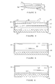
- FIG. 6 shows an alternate embodiment wherein baffle 24' is provided with a series of holes 26' across the bottom portion of baffle 24'.
- the function of holes 26' which are of uniform diameter, is to provide uniform friction across the entire width of nozzle tip 32 at its jointure to wall 16 of reservoir 2 to insure uniform entrance velocity of the molten metal into nozzle tip 32 in similar fashion to the function of opening 26 created by the position of baffle member 24.
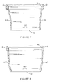
- Figures 9 through 16 illustrate typical metal velocity profiles which can be expected utilizing the teachings of the invention in a casting apparatus having a 68 inch wide tip and using respective casting rates of 80 lbs/hr/in and 180 lbs/hr/in.
- a spacer having a 1-1/2 inch chord length was located 5 inches from the exit port of the nozzle tip (measured from the trailing edge of the spacer). This location of the spacer from the exit port was possible because the Hele-Shaw flow conditions insure quicker recovery of the flat velocity profile downstream of the spacers.
- Figures 9, 10, 13 and 14 show measurements taken 7-1/2 inches from the exit port, i.e., before the metal flow encounters the leading edge of the spacer, while Figures 11, 12, 15 and 16 represent measurements taken 2-1/2 inches from the exit port, i.e., 2-1/2 inches beyond the trailing edge of the spacer.
- the metal velocity was measured parallel to the metal flow and perpendicular to the metal flow, i.e., toward the side risers. Hele-Shaw flow conditions ensure quicker-recovery of the flat velocity profile downstream of the spacers.
- the invention provides an improved flow control of molten metal from a reservoir to a rolling mechanism for the direct roll casting of metal plate or sheet from molten metal.
- Uniform metal velocity and temperature control within the nozzle tip assures the minimization of problems with sticking of metal to the rollers as well as heat transfer problems which have characterized prior art approaches in the past.
Landscapes
- Engineering & Computer Science (AREA)
- Mechanical Engineering (AREA)
- Continuous Casting (AREA)
- Peptides Or Proteins (AREA)
- Medicines That Contain Protein Lipid Enzymes And Other Medicines (AREA)
Applications Claiming Priority (8)
| Application Number | Priority Date | Filing Date | Title |
|---|---|---|---|
| US597912 | 1984-04-09 | ||
| US06/597,834 US4526223A (en) | 1984-04-09 | 1984-04-09 | Roll caster apparatus having converging tip assembly |
| US597911 | 1984-04-09 | ||
| US06/597,835 US4550766A (en) | 1984-04-09 | 1984-04-09 | Roll caster apparatus having nozzle tip assembly with novel spacer member |
| US597834 | 1984-04-09 | ||
| US06/597,912 US4550767A (en) | 1984-04-09 | 1984-04-09 | Roll caster apparatus having uniform flow of molten metal into novel nozzle tip assembly |
| US597835 | 1984-04-09 | ||
| US06/597,911 US4527612A (en) | 1984-04-09 | 1984-04-09 | Roll caster apparatus having nozzle tip assembly with improved molten metal flow conditions |
Publications (2)
| Publication Number | Publication Date |
|---|---|
| EP0159176A2 true EP0159176A2 (de) | 1985-10-23 |
| EP0159176A3 EP0159176A3 (de) | 1986-05-28 |
Family
ID=27505034
Family Applications (1)
| Application Number | Title | Priority Date | Filing Date |
|---|---|---|---|
| EP85302486A Withdrawn EP0159176A3 (de) | 1984-04-09 | 1985-04-09 | Stranggiessvorrichtung mit zwei Kühltrommeln |
Country Status (5)
| Country | Link |
|---|---|
| EP (1) | EP0159176A3 (de) |
| AU (1) | AU567805B2 (de) |
| BR (1) | BR8501631A (de) |
| CA (1) | CA1252754A (de) |
| NO (1) | NO851395L (de) |
Cited By (4)
| Publication number | Priority date | Publication date | Assignee | Title |
|---|---|---|---|---|
| DE3623937A1 (de) * | 1986-07-16 | 1988-01-21 | Didier Werke Ag | Feuerfeste kanalverbindung zum ueberfuehren von stahlschmelze in giessrad-stranggiessmaschinen |
| GB2247425A (en) * | 1990-07-13 | 1992-03-04 | Ishikawajima Harima Heavy Ind | Strip casting method and apparatus |
| WO1997025171A1 (en) * | 1996-01-11 | 1997-07-17 | Larex Ag | Improved nozzle with a baffle for a caster and an associated method of casting molten metal |
| EP1027183A4 (de) * | 1997-10-31 | 2004-06-23 | Fata Hunter Inc | Verstellbare zufuhrsystem für erschmolzenes metall |
Family Cites Families (5)
| Publication number | Priority date | Publication date | Assignee | Title |
|---|---|---|---|---|
| US2978761A (en) * | 1957-05-03 | 1961-04-11 | Kaiser Aluminium Chem Corp | Continuous casting apparatus |
| US3799410A (en) * | 1972-05-25 | 1974-03-26 | Nat Steel Corp | Feed tip for continuous casting machine |
| GB1540084A (en) * | 1975-04-08 | 1979-02-07 | Girling Ltd | Automatic adjusters for vehicle brakes |
| FR2398565A1 (fr) * | 1977-07-27 | 1979-02-23 | Scal Gp Condit Aluminium | Busette d'alimentation en metal liquide pour machine de coulee continue de bande |
| CA1208412A (en) * | 1982-04-28 | 1986-07-29 | Robert W. Hazelett | Methods and apparatus for feeding and continuously casting molten metal with inert gas applied to the moving mold surfaces and to the entering metal |
-
1985
- 1985-04-01 CA CA000478019A patent/CA1252754A/en not_active Expired
- 1985-04-03 NO NO851395A patent/NO851395L/no unknown
- 1985-04-04 AU AU40869/85A patent/AU567805B2/en not_active Expired - Fee Related
- 1985-04-08 BR BR8501631A patent/BR8501631A/pt unknown
- 1985-04-09 EP EP85302486A patent/EP0159176A3/de not_active Withdrawn
Cited By (5)
| Publication number | Priority date | Publication date | Assignee | Title |
|---|---|---|---|---|
| DE3623937A1 (de) * | 1986-07-16 | 1988-01-21 | Didier Werke Ag | Feuerfeste kanalverbindung zum ueberfuehren von stahlschmelze in giessrad-stranggiessmaschinen |
| GB2247425A (en) * | 1990-07-13 | 1992-03-04 | Ishikawajima Harima Heavy Ind | Strip casting method and apparatus |
| GB2247425B (en) * | 1990-07-13 | 1994-10-05 | Ishikawajima Harima Heavy Ind | Strip casting method |
| WO1997025171A1 (en) * | 1996-01-11 | 1997-07-17 | Larex Ag | Improved nozzle with a baffle for a caster and an associated method of casting molten metal |
| EP1027183A4 (de) * | 1997-10-31 | 2004-06-23 | Fata Hunter Inc | Verstellbare zufuhrsystem für erschmolzenes metall |
Also Published As
| Publication number | Publication date |
|---|---|
| NO851395L (no) | 1985-10-10 |
| BR8501631A (pt) | 1985-12-03 |
| AU4086985A (en) | 1985-10-17 |
| AU567805B2 (en) | 1987-12-03 |
| EP0159176A3 (de) | 1986-05-28 |
| CA1252754A (en) | 1989-04-18 |
Similar Documents
| Publication | Publication Date | Title |
|---|---|---|
| US4550767A (en) | Roll caster apparatus having uniform flow of molten metal into novel nozzle tip assembly | |
| US4550766A (en) | Roll caster apparatus having nozzle tip assembly with novel spacer member | |
| US4526223A (en) | Roll caster apparatus having converging tip assembly | |
| US4527612A (en) | Roll caster apparatus having nozzle tip assembly with improved molten metal flow conditions | |
| EP0606038A1 (de) | Vorrichtung zur Vorhangbeschichtung mit Randentfernung | |
| EP0159176A2 (de) | Stranggiessvorrichtung mit zwei Kühltrommeln | |
| US4394950A (en) | Apparatus for floatingly moving a length of material | |
| GB2096490A (en) | Spraying apparatus | |
| AT406026B (de) | Stranggiessanlage zum kontinuierlichen giessen eines dünnen bandes sowie verfahren hierzu | |
| PL177723B1 (pl) | Wlew doprowadzający ciekły metal do krystalizatora w procesie ciągłego odlewania aluminium | |
| US4321884A (en) | Coating thickness control nozzle | |
| US4955429A (en) | Apparatus for and process of direct casting of metal strip | |
| US3931848A (en) | Method and apparatus for cooling a strand cast in an oscillating mold during continuous casting of metals, especially steel | |
| CN1066806A (zh) | 金属带的铸造 | |
| WO2000001861A1 (en) | Improvements in jet stripping apparatus | |
| JP2744312B2 (ja) | 金属板を冷却するための線形水噴霧装置 | |
| EP0040073B1 (de) | Vorrichtung zum Giessen eines Streifens | |
| US4719963A (en) | Process for the production of a metal strand, more particularly in the form of a strip or section, by casting and apparatus for the performance of the process | |
| US4137347A (en) | Metallic coating method | |
| KR100194090B1 (ko) | 스트립 주조 방법 및 장치 | |
| US4913219A (en) | Process and device for casting thin strip or foil from the melt | |
| EP0649054A1 (de) | Vorrichtung und Verfahren für interne Kantenführungsstreifen | |
| US4237815A (en) | Apparatus for liquid coating thickness control and removing excess liquid coating from web edges | |
| JPH05138229A (ja) | 高温鋼板等の冷却装置 | |
| JPH0246533B2 (de) |
Legal Events
| Date | Code | Title | Description |
|---|---|---|---|
| PUAI | Public reference made under article 153(3) epc to a published international application that has entered the european phase |
Free format text: ORIGINAL CODE: 0009012 |
|
| AK | Designated contracting states |
Designated state(s): CH DE FR GB LI SE |
|
| PUAL | Search report despatched |
Free format text: ORIGINAL CODE: 0009013 |
|
| AK | Designated contracting states |
Kind code of ref document: A3 Designated state(s): CH DE FR GB LI SE |
|
| 17P | Request for examination filed |
Effective date: 19861124 |
|
| 17Q | First examination report despatched |
Effective date: 19870911 |
|
| RAP1 | Party data changed (applicant data changed or rights of an application transferred) |
Owner name: ALUMINUM COMPANY OF AMERICA |
|
| STAA | Information on the status of an ep patent application or granted ep patent |
Free format text: STATUS: THE APPLICATION IS DEEMED TO BE WITHDRAWN |
|
| 18D | Application deemed to be withdrawn |
Effective date: 19880525 |
|
| RIN1 | Information on inventor provided before grant (corrected) |
Inventor name: YU, HO Inventor name: AI, DANIEL K. |