EP0159220A1 - Schneckenvorrichtung zum Behandeln von Material - Google Patents
Schneckenvorrichtung zum Behandeln von Material Download PDFInfo
- Publication number
- EP0159220A1 EP0159220A1 EP85400420A EP85400420A EP0159220A1 EP 0159220 A1 EP0159220 A1 EP 0159220A1 EP 85400420 A EP85400420 A EP 85400420A EP 85400420 A EP85400420 A EP 85400420A EP 0159220 A1 EP0159220 A1 EP 0159220A1
- Authority
- EP
- European Patent Office
- Prior art keywords
- screw
- piston
- shaft
- nut
- elements
- Prior art date
- Legal status (The legal status is an assumption and is not a legal conclusion. Google has not performed a legal analysis and makes no representation as to the accuracy of the status listed.)
- Granted
Links
- 239000000463 material Substances 0.000 title claims description 15
- 239000012530 fluid Substances 0.000 claims description 5
- 238000009432 framing Methods 0.000 claims description 5
- 239000013013 elastic material Substances 0.000 claims description 2
- 239000002184 metal Substances 0.000 claims description 2
- 238000007789 sealing Methods 0.000 claims description 2
- 230000002093 peripheral effect Effects 0.000 claims 1
- 238000010276 construction Methods 0.000 abstract 1
- 238000000926 separation method Methods 0.000 abstract 1
- 239000011295 pitch Substances 0.000 description 8
- 238000005452 bending Methods 0.000 description 6
- 230000000694 effects Effects 0.000 description 4
- 238000011144 upstream manufacturing Methods 0.000 description 3
- 230000006835 compression Effects 0.000 description 2
- 238000007906 compression Methods 0.000 description 2
- 230000008595 infiltration Effects 0.000 description 2
- 238000001764 infiltration Methods 0.000 description 2
- 230000001788 irregular Effects 0.000 description 2
- 230000005540 biological transmission Effects 0.000 description 1
- 230000000903 blocking effect Effects 0.000 description 1
- 238000001125 extrusion Methods 0.000 description 1
- 238000004898 kneading Methods 0.000 description 1
- 238000004519 manufacturing process Methods 0.000 description 1
- 238000000034 method Methods 0.000 description 1
- 238000002156 mixing Methods 0.000 description 1
- 229920003023 plastic Polymers 0.000 description 1
- 239000004033 plastic Substances 0.000 description 1
- 230000036316 preload Effects 0.000 description 1
- 238000007790 scraping Methods 0.000 description 1
- 238000001665 trituration Methods 0.000 description 1
Images

Classifications
-
- B—PERFORMING OPERATIONS; TRANSPORTING
- B30—PRESSES
- B30B—PRESSES IN GENERAL
- B30B11/00—Presses specially adapted for forming shaped articles from material in particulate or plastic state, e.g. briquetting presses, tabletting presses
- B30B11/22—Extrusion presses; Dies therefor
- B30B11/24—Extrusion presses; Dies therefor using screws or worms
- B30B11/246—Screw constructions
-
- B—PERFORMING OPERATIONS; TRANSPORTING
- B29—WORKING OF PLASTICS; WORKING OF SUBSTANCES IN A PLASTIC STATE IN GENERAL
- B29B—PREPARATION OR PRETREATMENT OF THE MATERIAL TO BE SHAPED; MAKING GRANULES OR PREFORMS; RECOVERY OF PLASTICS OR OTHER CONSTITUENTS OF WASTE MATERIAL CONTAINING PLASTICS
- B29B7/00—Mixing; Kneading
- B29B7/30—Mixing; Kneading continuous, with mechanical mixing or kneading devices
- B29B7/34—Mixing; Kneading continuous, with mechanical mixing or kneading devices with movable mixing or kneading devices
- B29B7/38—Mixing; Kneading continuous, with mechanical mixing or kneading devices with movable mixing or kneading devices rotary
- B29B7/46—Mixing; Kneading continuous, with mechanical mixing or kneading devices with movable mixing or kneading devices rotary with more than one shaft
- B29B7/48—Mixing; Kneading continuous, with mechanical mixing or kneading devices with movable mixing or kneading devices rotary with more than one shaft with intermeshing devices, e.g. screws
- B29B7/482—Mixing; Kneading continuous, with mechanical mixing or kneading devices with movable mixing or kneading devices rotary with more than one shaft with intermeshing devices, e.g. screws provided with screw parts in addition to other mixing parts, e.g. paddles, gears, discs
-
- B—PERFORMING OPERATIONS; TRANSPORTING
- B29—WORKING OF PLASTICS; WORKING OF SUBSTANCES IN A PLASTIC STATE IN GENERAL
- B29C—SHAPING OR JOINING OF PLASTICS; SHAPING OF MATERIAL IN A PLASTIC STATE, NOT OTHERWISE PROVIDED FOR; AFTER-TREATMENT OF THE SHAPED PRODUCTS, e.g. REPAIRING
- B29C48/00—Extrusion moulding, i.e. expressing the moulding material through a die or nozzle which imparts the desired form; Apparatus therefor
- B29C48/25—Component parts, details or accessories; Auxiliary operations
- B29C48/256—Exchangeable extruder parts
- B29C48/2562—Mounting or handling of the die
-
- B—PERFORMING OPERATIONS; TRANSPORTING
- B29—WORKING OF PLASTICS; WORKING OF SUBSTANCES IN A PLASTIC STATE IN GENERAL
- B29C—SHAPING OR JOINING OF PLASTICS; SHAPING OF MATERIAL IN A PLASTIC STATE, NOT OTHERWISE PROVIDED FOR; AFTER-TREATMENT OF THE SHAPED PRODUCTS, e.g. REPAIRING
- B29C48/00—Extrusion moulding, i.e. expressing the moulding material through a die or nozzle which imparts the desired form; Apparatus therefor
- B29C48/25—Component parts, details or accessories; Auxiliary operations
- B29C48/256—Exchangeable extruder parts
- B29C48/2564—Screw parts
-
- B—PERFORMING OPERATIONS; TRANSPORTING
- B29—WORKING OF PLASTICS; WORKING OF SUBSTANCES IN A PLASTIC STATE IN GENERAL
- B29C—SHAPING OR JOINING OF PLASTICS; SHAPING OF MATERIAL IN A PLASTIC STATE, NOT OTHERWISE PROVIDED FOR; AFTER-TREATMENT OF THE SHAPED PRODUCTS, e.g. REPAIRING
- B29C48/00—Extrusion moulding, i.e. expressing the moulding material through a die or nozzle which imparts the desired form; Apparatus therefor
- B29C48/25—Component parts, details or accessories; Auxiliary operations
- B29C48/36—Means for plasticising or homogenising the moulding material or forcing it through the nozzle or die
- B29C48/50—Details of extruders
- B29C48/505—Screws
- B29C48/58—Screws provided with seal ring elements, i.e. elements of generally circular and tapered shape for preventing the back flow of the melt
-
- B—PERFORMING OPERATIONS; TRANSPORTING
- B29—WORKING OF PLASTICS; WORKING OF SUBSTANCES IN A PLASTIC STATE IN GENERAL
- B29C—SHAPING OR JOINING OF PLASTICS; SHAPING OF MATERIAL IN A PLASTIC STATE, NOT OTHERWISE PROVIDED FOR; AFTER-TREATMENT OF THE SHAPED PRODUCTS, e.g. REPAIRING
- B29C48/00—Extrusion moulding, i.e. expressing the moulding material through a die or nozzle which imparts the desired form; Apparatus therefor
- B29C48/03—Extrusion moulding, i.e. expressing the moulding material through a die or nozzle which imparts the desired form; Apparatus therefor characterised by the shape of the extruded material at extrusion
Definitions
- the subject of the invention is a material processing screw machine comprising at least one screw driven in rotation inside a sheath.
- the invention applies especially to extruders with one or more screws and, more generally, to machines in which effects of mixing, kneading, trituration and pressurization are produced by passing a entrained material through the sheath by rotating the screws.
- these screws sometimes consist of threaded elements in the form of hollow sleeves threaded on a central drive shaft so as to form a contiguous stack integral with the rotating shaft thanks, for example, to grooves protruding from the shaft and engaging in corresponding grooves formed on the inner wall of the sleeves.
- These are stacked and wedged between two stops placed at the two ends of the shaft, generally a fixed stop placed at one end and a tightening nut screwed onto a thread made at the other end of the shaft. Thanks to this arrangement, it is possible to easily change one or more threaded elements either to modify the pitch of the threads, or to replace a used element.
- the material entrained in the screws is generally pressurized and therefore tends to spread apart the adjacent elements and to infiltrate between them. It can then reach the grooves and possibly harden. The disassembly of the elements then becomes difficult and it is necessary to clean the splined shaft each time that the elements are changed, this operation can be quite long.
- the clamping nut is used only to secure the elements together and, as it must be easily disassembled, it cannot exert sufficient pressure to undoubtedly oppose a spacing of the elements allowing infiltration matter.
- the screw shafts must obviously be kept in bearings.
- the screws are held by bearings located only on the side of the drive. At their other end, they are kept centered relative to the sheath by the pressure of the extruded material.
- the machine does not operate as an extruder but, for example, as a mixer.
- the material may not be pressurized at the downstream end and be discharged through a lateral orifice of the sheath. In this case, it is more normal to have each screw carried by two bearings placed at its two ends.
- the invention relates to improvements which make it possible to remedy these drawbacks.
- the means for tightening the wire elements, tees is arranged so as to exert on the stack an effort of prestressing capable of opposing the detachment in service of the wire elements one with respect to the other.
- the clamping means includes a hydraulic cylinder consisting of a piston and a cylindrical body bearing one on the central shaft, the other on the stack and a means mechanical locking of the piston relative to the body after prestressing the stack.
- the clamping cylinder comprises a nut screwed onto a corresponding thread of the central shaft and on which are provided two cylindrical bearing surfaces of different diameters framing an annular bearing surface and along which the cylindrical body is slidably mounted, the latter being provided internally with two cylindrical bearing surfaces of internal diameters equal respectively to the external diameters of the bearing surfaces of the nut and framing an annular bearing surface opposite to that of the nut; the space between the two annular bearings forms a jack chamber closed by seals interposed between the cylindrical bearings of the same diameters and which can be connected to a means for supplying pressurized fluid.
- the means for blocking the piston with respect to the cylindrical body is constituted by a nut screwed onto one of these two parts and provided with hooking means on the other part opposing the sliding thereof after
- the threaded elements are symmetrical with respect to a median plane perpendicular to their axis so that after use in one direction, they can be turned over for use in the other direction
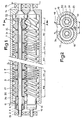
- Figure 1 there is shown, in longitudinal section through a plane passing through the axes of the screws, a machine comprising, inside a sheath 1, two screws 11 and 12 with axes 10 parallel, carried at their ends by steps 13 and 14.
- the two screws 11 and 12 are rotated in the same direction by a drive group 15 and their threads are therefore identical.
- the material, introduced through an upstream orifice 16 centered in the plane of symmetry of the sheath is entrained downstream by a conveying section A with wide pitch and then compressed in a tight pitch section B I preceding a braking section C l which may consist, for example, of threads with inverted pitch provided with openings for passage of the material downstream.
- the material is therefore strongly compressed in section B ⁇ .
- the material then expands in a section B 2 with direct pitch then compresses again before passing into a new braking section C 2 , and so on until the downstream end of the sheath provided with an outlet orifice 17.
- Each screw will therefore consist, conventionally, of a shaft 2 on which are threaded one after the other elements 3 thus constituting a stack.
- Each element 3 comprises a cylindrical central part 31, provided on its periphery with one or more threads 32 wound in a helix according to a pitch specific to the element.
- the shaft 2 is advantageously provided with grooves 21 which engage in corresponding grooves 33 formed on the internal wall of the cylindrical part 31 of the element.
- the two screws mesh with one another and are therefore placed in two intersecting cylindrical lobes 18 with a diameter slightly greater than the outside diameter of the threads 32.
- the spacing (a) of the screws is less than their diameter, the difference being a little greater than the depth of the threads, so that the periphery of the thread of a screw 11 is spaced from the bottom of the thread of the other screw 12 by a clearance (b).
- the profile of the threads is such that they are tangent to each other in the meshing section 34 so as to produce a scraping effect.
- the contiguous stack thus formed is wedged between two stops, a fixed stop 22 placed at one end of the shaft and a movable stop placed at the other end and constituted, generally, by an internally threaded nut and screwed on a corresponding thread formed at the end of the shaft 2.
- a nut only serves to hold the threaded elements on the shaft 2 but is not intended to exert a very high clamping pressure.
- this means of tightening is constituted by a hydromechanical nut 4, shown in detail in FIG. 3 and which can exert a real prestressing force on the elements 3 likely to oppose their detachment in service.
- the nut 4 is provided with an internal thread 41 which can be screwed onto a corresponding thread 23 formed at the end of the shaft 2.
- the nut 4 is provided with two cylindrical bearing surfaces 42, 43 of different diameters framing an annular wall 44 and thus defining an annular piston 45; the latter is surrounded by a cylindrical sleeve 5 provided with an internal bore defining two cylindrical bearing surfaces 52, 53 of diameters equal, respectively, to those of the bearing surfaces 42 and 43 of the nut and which frame an annular wall 54 opposite the wall 44 of the nut 4.
- the sleeve 5 thus forms the body of a hydraulic cylinder whose piston is constituted by the part 45 of the nut 4, the latter comprising a conduit 46 which opens into the chamber 55 of the cylinder formed between the annular walls 44 and 54, and can be connected to a means for supplying pressurized fluid.
- the chamber 55 of the jack can thus be pressurized, its sealing being ensured by seals 56, 57 interposed between the corresponding cylindrical bearings 42, 52 and 43, 53.
- the nut 4 is screwed onto the thread 23 until come into abutment at its end 47 on the first element 35 of the stack, for example by means of a sleeve 36 passing through, in a leaktight manner, the end of the sheath 1.
- the chamber 55 of the cylinder and, the nut 4 being blocked, the cylindrical body 5 moves on the side of the stack to come to bear on the sleeve 36 by its end 58.
- the screw elements 3 are therefore subjected to a pressure determining a force prestress which can be measured by controlling the supply pressure of the cylinder.
- the hydromechanical nut which has just been described makes it possible to obtain very large prestressing forces, of the order of 20 tonnes, for example, for screws having a center distance (a) of 200 mm.
- the nut 4 is provided with a locking means constituted by a nut 6 screwed onto a thread 61 formed on the periphery of the nut 4. After having pressurized the cylinder, it suffices to turn the locking nut 6 in the desired direction to lock the two parts 4 and 5 of the cylinder in relative position and therefore maintain the preload of the screw elements. We can then remove the pressure in the chamber 55 of the cylinder. Furthermore, the nut 4 is provided with a hooking ring 62 engaging in a corresponding groove 63 formed on the periphery of the body 5 of the jack. After loosening the jack, the ring 62 allows, by rotation of the nut 6, to bring the annular faces 44 and 54 of the piston 4 and of the body 5 of the jack back into contact.
- the threaded elements 3 are separated by seals 7 symmetrical with respect to the transverse planes P 2 of junction between the adjacent elements.
- the elements 3 are provided with two half-grooves 71, 72 formed respectively at each end of the internal wall of the central part 31 of the element 3 and which, by joining two adjacent elements, form a symmetrical groove relative to the plane P 2 and in which the seal 7 can be housed.
- the height of the groove and of the seal must be limited so that the bearing faces 36 have a cross section sufficient for the transmission of the force of prestressed, without risk of crushing.
- the seal 7, as shown in Figure 4 consists of a ring of elastic material 73 attached to a metal ring 74 whose internal diameter is equal to outer diameter of the grooves 21 of the shaft 2.
- the elastic ring 73 is well maintained at the bottom of the groove 71, 72, the thickness of the ring 74 being greater than the play existing between the grooves 21 of l 'shaft 2 and the corresponding grooves 33 of the screw elements 3 so as to avoid the extrusion of the ring 73.
- the seal 7 advantageously consists of two lips symmetrical with respect to the plane P 2 and which apply to the lateral sides of the half-grooves 71, 72 by circular edges 75.
- the threaded elements 3 are therefore symmetrical with respect to their median planes and can be turned over after use in one direction. Indeed, in the conveying sections B l , for example, the threads 32 are worn essentially on their downstream face 320, in particular at the angle of the thread 321, the upstream angle 322 being subjected to less significant forces. This results in irregular wear of the net. In the previous arrangements, the bending of the screws caused irregular matting of the bearing faces 36 which prevented the elements from turning over. Thanks to the arrangement according to the invention, the bearing faces 36 are subjected to a regularly distributed pressure, which avoids the risks of dulling. We can therefore return the threaded elements after use in one direction for a new use in another direction, which doubles the life of the elements.
- the invention is particularly advantageous in the case which has just been described, of a machine with several screws carried by bearings at their two ends and therefore subjected to bending, but it remains advantageous for extruders with one or more screws with bearings only on the upstream side.
Landscapes
- Engineering & Computer Science (AREA)
- Mechanical Engineering (AREA)
- Extrusion Moulding Of Plastics Or The Like (AREA)
- Processing And Handling Of Plastics And Other Materials For Molding In General (AREA)
- Crushing And Pulverization Processes (AREA)
- Transmission Devices (AREA)
- Formation And Processing Of Food Products (AREA)
- Steroid Compounds (AREA)
- Mixers Of The Rotary Stirring Type (AREA)
- Screw Conveyors (AREA)
Priority Applications (1)
| Application Number | Priority Date | Filing Date | Title |
|---|---|---|---|
| AT85400420T ATE29240T1 (de) | 1984-03-08 | 1985-03-05 | Schneckenvorrichtung zum behandeln von material. |
Applications Claiming Priority (2)
| Application Number | Priority Date | Filing Date | Title |
|---|---|---|---|
| FR8403583 | 1984-03-08 | ||
| FR8403583A FR2560817B1 (fr) | 1984-03-08 | 1984-03-08 | Machine a vis de traitement de matiere |
Publications (2)
| Publication Number | Publication Date |
|---|---|
| EP0159220A1 true EP0159220A1 (de) | 1985-10-23 |
| EP0159220B1 EP0159220B1 (de) | 1987-09-02 |
Family
ID=9301823
Family Applications (1)
| Application Number | Title | Priority Date | Filing Date |
|---|---|---|---|
| EP85400420A Expired EP0159220B1 (de) | 1984-03-08 | 1985-03-05 | Schneckenvorrichtung zum Behandeln von Material |
Country Status (12)
| Country | Link |
|---|---|
| US (1) | US4600311A (de) |
| EP (1) | EP0159220B1 (de) |
| AT (1) | ATE29240T1 (de) |
| AU (1) | AU572269B2 (de) |
| BR (1) | BR8501037A (de) |
| CA (1) | CA1249808A (de) |
| DE (1) | DE3560523D1 (de) |
| ES (1) | ES8606122A1 (de) |
| FI (1) | FI76732C (de) |
| FR (1) | FR2560817B1 (de) |
| NO (1) | NO163888C (de) |
| ZA (1) | ZA851717B (de) |
Cited By (1)
| Publication number | Priority date | Publication date | Assignee | Title |
|---|---|---|---|---|
| EP0641640A1 (de) * | 1993-09-02 | 1995-03-08 | Werner & Pfleiderer GmbH | Schneckenelement für eine Schneckenmaschine |
Families Citing this family (51)
| Publication number | Priority date | Publication date | Assignee | Title |
|---|---|---|---|---|
| US4746220A (en) * | 1985-04-18 | 1988-05-24 | Noritake Co., Limited | Screw type extruding or kneading machine and screw used therein |
| FR2601380B1 (fr) * | 1986-07-08 | 1989-08-18 | Clextral | Procede et dispositif pour la fabrication en continu de combustibles mixtes a base de matieres organiques et de matieres hydrocarbonees |
| FR2607431B1 (fr) * | 1986-12-02 | 1989-03-10 | Clextral | Procede et installation de montage et demontage des vis d'une machine d'extrusion |
| US4834913A (en) * | 1987-01-27 | 1989-05-30 | Aseltine Leroy G | Apparatus and method for forming finely divided dry materials from wet materials having a tendency to form lumps |
| US5044759A (en) * | 1987-05-20 | 1991-09-03 | Giuseppe Gagliani | Mixing process and screw extruders for carrying out the same |
| US4932223A (en) * | 1989-04-07 | 1990-06-12 | Scotsman Industries | Auger construction for ice-making apparatus |
| WO1992013711A1 (en) * | 1991-02-04 | 1992-08-20 | Stord International A/S | Arrangement in intake for double-screw press |
| DE4134026C2 (de) * | 1991-10-15 | 1994-04-21 | Werner & Pfleiderer | Gleichdrallschneckenkneter |
| US5520454A (en) * | 1994-09-09 | 1996-05-28 | Industrial Technology Research Institute | Injection screw set for an injection molding machine |
| US5638745A (en) * | 1995-04-03 | 1997-06-17 | Fmc Corporation | Juice finisher |
| US6062719A (en) * | 1996-09-24 | 2000-05-16 | The Dow Chemical Company | High efficiency extruder |
| DE19641235A1 (de) * | 1996-10-07 | 1998-05-28 | Compex Gmbh Compoundier Und Ex | Mehrwellige kontinuierlich arbeitende Mischmaschine für plastifizierbare Massen |
| DE19847104C1 (de) * | 1998-10-13 | 1999-10-28 | 3 & Extruder Gmbh | Mehrwellige Schneckenmaschine |
| US7763341B2 (en) * | 2004-01-23 | 2010-07-27 | Century-Board Usa, Llc | Filled polymer composite and synthetic building material compositions |
| CN101111353B (zh) | 2004-06-24 | 2011-09-28 | 世纪-博得美国公司 | 用于三维泡沫产品的连续成型设备 |
| US7887870B2 (en) | 2004-08-16 | 2011-02-15 | Solae, Llc | Restructured meat product and process for preparing same |
| DE102004052055B4 (de) * | 2004-10-26 | 2014-11-20 | Blach Verwaltung Gmbh & Co.Kg | Extruder |
| US20070225419A1 (en) | 2006-03-24 | 2007-09-27 | Century-Board Usa, Llc | Polyurethane composite materials |
| MX2008014605A (es) | 2006-05-19 | 2008-11-28 | Solae Llc | Composicion de proteina y su uso en carne reestructurada y productos alimenticios. |
| ITMO20060207A1 (it) * | 2006-06-27 | 2007-12-28 | Wam Spa | Coclea da utilizzarsi per trasportatori, compattatori e simili. |
| US20080102165A1 (en) * | 2006-09-28 | 2008-05-01 | Solae, Llc | Extruded Protein Compositions |
| DE102006057290B4 (de) | 2006-12-05 | 2008-10-30 | British American Tobacco (Germany) Gmbh | Tabakzerfaserung mit zweiseitig gelagerter Förderschneckenwelle |
| JP5005506B2 (ja) * | 2007-11-02 | 2012-08-22 | 株式会社神戸製鋼所 | 混練度調整方法 |
| US20090155448A1 (en) * | 2007-12-12 | 2009-06-18 | Solae, Llc | Organic Protein Extrudates and Preparation Thereof |
| US20100062093A1 (en) * | 2008-09-11 | 2010-03-11 | Wenger Manufacturing, Inc. | Method and apparatus for producing fully cooked extrudates with significantly reduced specific mechanical energy inputs |
| US8846776B2 (en) | 2009-08-14 | 2014-09-30 | Boral Ip Holdings Llc | Filled polyurethane composites and methods of making same |
| US9481759B2 (en) | 2009-08-14 | 2016-11-01 | Boral Ip Holdings Llc | Polyurethanes derived from highly reactive reactants and coal ash |
| US9738047B2 (en) * | 2015-09-26 | 2017-08-22 | Nationwide 5, Llc | Compression screw for producing animal feed |
| HUE039003T2 (hu) | 2011-05-13 | 2018-12-28 | Ojah B V | Módszer a strukturált fehérjekészítmények elõállítására |
| WO2013052732A1 (en) | 2011-10-07 | 2013-04-11 | Boral Industries Inc. | Inorganic polymer/organic polymer composites and methods of making same |
| TW201336661A (zh) * | 2012-03-09 | 2013-09-16 | jia-qing Chen | 套筒加工機 |
| US10863765B2 (en) | 2012-10-24 | 2020-12-15 | Nationwide 5, Llc | High-fat and high-protein animal feed supplement and process of manufacture |
| FR2997314B1 (fr) * | 2012-10-30 | 2016-01-08 | Herakles | Dispositif de malaxage muni d'un dispositif de maintien d'arbres |
| WO2014168633A1 (en) | 2013-04-12 | 2014-10-16 | Boral Ip Holdings (Australia) Pty Limited | Composites formed from an absorptive filler and a polyurethane |
| US9713893B2 (en) * | 2013-07-09 | 2017-07-25 | Wenger Manufacturing, Inc. | Method of preconditioning comestible materials using steam/water static mixer |
| US20150131399A1 (en) * | 2013-11-12 | 2015-05-14 | Zzyzx Polymers LLC | Systems and methods of regulating temperature of a solid-state shear pulverization or solid-state melt extrusion device |
| CN103753849B (zh) * | 2014-01-06 | 2015-08-19 | 湖北合加环境设备有限公司 | 智能型rdf环模成型机 |
| JP6639799B2 (ja) * | 2014-05-08 | 2020-02-05 | 東芝機械株式会社 | 混練装置および混練方法 |
| JP6639798B2 (ja) | 2014-05-08 | 2020-02-05 | 東芝機械株式会社 | 押出機用スクリュ並びに押出機および押出方法 |
| JP6639800B2 (ja) * | 2014-05-08 | 2020-02-05 | 東芝機械株式会社 | 押出機用スクリュ並びに押出機および押出方法 |
| WO2016018226A1 (en) | 2014-07-28 | 2016-02-04 | Crocco Guy | The use of evaporative coolants to manufacture filled polyurethane composites |
| WO2016022103A1 (en) | 2014-08-05 | 2016-02-11 | Amitabha Kumar | Filled polymeric composites including short length fibers |
| JP6446234B2 (ja) * | 2014-10-27 | 2018-12-26 | 東芝機械株式会社 | 押出機用スクリュ、スクリュエレメント、押出機および押出方法 |
| US9988512B2 (en) | 2015-01-22 | 2018-06-05 | Boral Ip Holdings (Australia) Pty Limited | Highly filled polyurethane composites |
| WO2016195717A1 (en) | 2015-06-05 | 2016-12-08 | Boral Ip Holdings (Australia) Pty Limited | Filled polyurethane composites with lightweight fillers |
| US11019836B2 (en) | 2015-08-03 | 2021-06-01 | Savage River, Inc. | Food products comprising cell wall material |
| US20170267585A1 (en) | 2015-11-12 | 2017-09-21 | Amitabha Kumar | Filled polyurethane composites with size-graded fillers |
| EP3481221B1 (de) | 2016-07-10 | 2025-08-27 | Yissum Research and Development Company of the Hebrew University of Jerusalem Ltd. | Verfahren zur herstellung von kichererbsenproteinkonzentrat |
| WO2019115407A1 (en) | 2017-12-11 | 2019-06-20 | Roquette Freres | High protein crips |
| US12133550B2 (en) * | 2018-12-14 | 2024-11-05 | China Tobacco Hunan Industrial Co., Ltd. | Molding apparatus, cigarette filter rod and preparation method thereof |
| CN110116489A (zh) * | 2019-05-22 | 2019-08-13 | 义乌紫英机械科技有限公司 | 一种塑料制品加工用高频共振熔融挤出机 |
Citations (6)
| Publication number | Priority date | Publication date | Assignee | Title |
|---|---|---|---|---|
| US2946089A (en) * | 1957-11-27 | 1960-07-26 | Nat Rubber Machinery Co | Extruder with jointed feed screw |
| DE1110474B (de) * | 1955-01-10 | 1961-07-06 | Spieth Rudolf | Hydraulische Spanneinrichtung zum loesbaren Verbinden von Maschinenteilen und Werkzeugen |
| FR2042191A5 (de) * | 1969-04-19 | 1971-02-05 | Berstorff Gmbh Masch Hermann | |
| FR2264628A1 (de) * | 1974-03-21 | 1975-10-17 | Schrem Kg Albert | |
| FR2401754A1 (fr) * | 1977-09-06 | 1979-03-30 | Berstorff Gmbh Masch Hermann | Machine monovis ou multivis |
| DE2924462A1 (de) * | 1979-06-18 | 1981-01-22 | Josef A Blach | Materialbearbeitungswelle fuer maschinen zur bearbeitung fester, fluessiger, plastischer und/oder zaehviskoser materialien |
Family Cites Families (4)
| Publication number | Priority date | Publication date | Assignee | Title |
|---|---|---|---|---|
| NL131340C (de) * | 1963-11-27 | 1900-01-01 | ||
| DE1502335B2 (de) * | 1965-02-13 | 1971-10-21 | Werner & Pfleiderer, 7000 Stuttgart | Schneckenstrangprese fuer die verarbeitung von kunststoff |
| US3850414A (en) * | 1972-12-26 | 1974-11-26 | H Scharer | Homogenizing extruders |
| DE3026842C2 (de) * | 1980-07-16 | 1984-02-16 | Hermann Berstorff Maschinenbau Gmbh, 3000 Hannover | Doppelschnecken-Entgasungsextruder für thermoplastische Materialien |
-
1984
- 1984-03-08 FR FR8403583A patent/FR2560817B1/fr not_active Expired
-
1985
- 1985-03-05 DE DE8585400420T patent/DE3560523D1/de not_active Expired
- 1985-03-05 AT AT85400420T patent/ATE29240T1/de not_active IP Right Cessation
- 1985-03-05 FI FI850884A patent/FI76732C/fi not_active IP Right Cessation
- 1985-03-05 EP EP85400420A patent/EP0159220B1/de not_active Expired
- 1985-03-06 ES ES540996A patent/ES8606122A1/es not_active Expired
- 1985-03-07 CA CA000475984A patent/CA1249808A/en not_active Expired
- 1985-03-07 BR BR8501037A patent/BR8501037A/pt not_active IP Right Cessation
- 1985-03-07 US US06/709,273 patent/US4600311A/en not_active Expired - Fee Related
- 1985-03-07 ZA ZA851717A patent/ZA851717B/xx unknown
- 1985-03-07 NO NO850912A patent/NO163888C/no unknown
- 1985-03-07 AU AU39619/85A patent/AU572269B2/en not_active Ceased
Patent Citations (6)
| Publication number | Priority date | Publication date | Assignee | Title |
|---|---|---|---|---|
| DE1110474B (de) * | 1955-01-10 | 1961-07-06 | Spieth Rudolf | Hydraulische Spanneinrichtung zum loesbaren Verbinden von Maschinenteilen und Werkzeugen |
| US2946089A (en) * | 1957-11-27 | 1960-07-26 | Nat Rubber Machinery Co | Extruder with jointed feed screw |
| FR2042191A5 (de) * | 1969-04-19 | 1971-02-05 | Berstorff Gmbh Masch Hermann | |
| FR2264628A1 (de) * | 1974-03-21 | 1975-10-17 | Schrem Kg Albert | |
| FR2401754A1 (fr) * | 1977-09-06 | 1979-03-30 | Berstorff Gmbh Masch Hermann | Machine monovis ou multivis |
| DE2924462A1 (de) * | 1979-06-18 | 1981-01-22 | Josef A Blach | Materialbearbeitungswelle fuer maschinen zur bearbeitung fester, fluessiger, plastischer und/oder zaehviskoser materialien |
Cited By (1)
| Publication number | Priority date | Publication date | Assignee | Title |
|---|---|---|---|---|
| EP0641640A1 (de) * | 1993-09-02 | 1995-03-08 | Werner & Pfleiderer GmbH | Schneckenelement für eine Schneckenmaschine |
Also Published As
| Publication number | Publication date |
|---|---|
| FR2560817B1 (fr) | 1988-06-24 |
| AU3961985A (en) | 1985-09-12 |
| NO163888C (no) | 1990-08-15 |
| ES8606122A1 (es) | 1986-04-16 |
| US4600311A (en) | 1986-07-15 |
| ATE29240T1 (de) | 1987-09-15 |
| AU572269B2 (en) | 1988-05-05 |
| BR8501037A (pt) | 1985-10-29 |
| FI850884L (fi) | 1985-09-09 |
| DE3560523D1 (en) | 1987-10-08 |
| FI76732B (fi) | 1988-08-31 |
| FI76732C (fi) | 1988-12-12 |
| FR2560817A1 (fr) | 1985-09-13 |
| NO163888B (no) | 1990-04-30 |
| EP0159220B1 (de) | 1987-09-02 |
| FI850884A0 (fi) | 1985-03-05 |
| ZA851717B (en) | 1985-11-27 |
| NO850912L (no) | 1985-09-09 |
| ES540996A0 (es) | 1986-04-16 |
| CA1249808A (en) | 1989-02-07 |
Similar Documents
| Publication | Publication Date | Title |
|---|---|---|
| EP0159220B1 (de) | Schneckenvorrichtung zum Behandeln von Material | |
| EP3325248B1 (de) | Vorrichtung und verfahren zur reinigung eines extruders für elastomermischungen | |
| BE897900A (fr) | Liaison entre un premier élément et un alésage formé dans un second élément. | |
| WO1988006250A1 (fr) | Piston pour moteurs a combustion interne et machines analogues | |
| FR2712041A1 (fr) | Moteur oscillant hydraulique, et ses unités de joint d'étanchéité. | |
| EP0220088B1 (de) | Schraubverbindung für Stahlrohre mit Dichtungsvorrichtung im Bereich des Gewindes | |
| FR2739147A1 (fr) | Pompe a vis uniaxe excentrique | |
| CN100542782C (zh) | 挤出机 | |
| FR3026455A1 (fr) | Mecanisme de vis a rouleaux a couronnes integrees et procede de fabrication associe | |
| FR2750744A1 (fr) | Pompe pour fluides alimentaires ou pharmaceutiques a etanchement ameliore | |
| EP3538342B1 (de) | Anordnung zur volumetrischen extrusion für elastomermischungen | |
| CA2743401C (fr) | Bague pour palier hydrostatique ou hydrodynamique, machine hydraulique equipee d'une telle bague et procede de montage d'une telle bague sur un arbre | |
| FR2971190A1 (fr) | Vis destinee a l'extrusion ou au melangeage d'elastomeres ou de produits plastiques pour la fabrication de pneumatiques | |
| FR2559561A1 (fr) | Douille a bride en poudre de metal frittee pour monter un organe d'une machine sur un arbre | |
| EP1248529A1 (de) | Verfahren und vorrichtung zur kontinuierlichen herstellung von caseinaten | |
| FR2473390A1 (fr) | Tete d'entrainement, notamment pour serrer ou desserrer des goujons filetes ou des elements analogues | |
| EP3558625B1 (de) | Extrusionsanlage mit einem verbesserten extrusionskopf | |
| FR2767889A1 (fr) | Roue directrice de convertisseur de couple de rotation fabriquee par injection | |
| EP0157680B1 (de) | Schneckenelement für eine Materialbehandlungsvorrichtung | |
| FR2492022A1 (fr) | Dispositif d'accouplement rigide monte sous pression de fluide | |
| WO2018115797A1 (fr) | Installation d'extrusion comportant une tête d'extrusion perfectionnée | |
| FR2742683A1 (fr) | Dispositif tournant de coulee continue | |
| FR2991410A1 (fr) | Ensemble de serrage a vis | |
| FR2755888A1 (fr) | Procede d'usinage d'un alesage dans un fourreau d'une machine d'extrusion et fourreau de machine d'extrusion | |
| FR2816878A1 (fr) | Procede de fabrication d'un tube spirale souple et installation mettant en oeuvre ledit procede |
Legal Events
| Date | Code | Title | Description |
|---|---|---|---|
| PUAI | Public reference made under article 153(3) epc to a published international application that has entered the european phase |
Free format text: ORIGINAL CODE: 0009012 |
|
| AK | Designated contracting states |
Designated state(s): AT BE CH DE GB IT LI SE |
|
| 17P | Request for examination filed |
Effective date: 19850918 |
|
| 17Q | First examination report despatched |
Effective date: 19860417 |
|
| GRAA | (expected) grant |
Free format text: ORIGINAL CODE: 0009210 |
|
| AK | Designated contracting states |
Kind code of ref document: B1 Designated state(s): AT BE CH DE GB IT LI SE |
|
| REF | Corresponds to: |
Ref document number: 29240 Country of ref document: AT Date of ref document: 19870915 Kind code of ref document: T |
|
| ITF | It: translation for a ep patent filed | ||
| REF | Corresponds to: |
Ref document number: 3560523 Country of ref document: DE Date of ref document: 19871008 |
|
| GBT | Gb: translation of ep patent filed (gb section 77(6)(a)/1977) | ||
| PLBE | No opposition filed within time limit |
Free format text: ORIGINAL CODE: 0009261 |
|
| STAA | Information on the status of an ep patent application or granted ep patent |
Free format text: STATUS: NO OPPOSITION FILED WITHIN TIME LIMIT |
|
| 26N | No opposition filed | ||
| ITTA | It: last paid annual fee | ||
| EAL | Se: european patent in force in sweden |
Ref document number: 85400420.7 |
|
| PGFP | Annual fee paid to national office [announced via postgrant information from national office to epo] |
Ref country code: AT Payment date: 19950224 Year of fee payment: 11 |
|
| PGFP | Annual fee paid to national office [announced via postgrant information from national office to epo] |
Ref country code: BE Payment date: 19950329 Year of fee payment: 11 |
|
| PG25 | Lapsed in a contracting state [announced via postgrant information from national office to epo] |
Ref country code: AT Effective date: 19960305 |
|
| PG25 | Lapsed in a contracting state [announced via postgrant information from national office to epo] |
Ref country code: BE Effective date: 19960331 |
|
| BERE | Be: lapsed |
Owner name: CLEXTRAL Effective date: 19960331 |
|
| PGFP | Annual fee paid to national office [announced via postgrant information from national office to epo] |
Ref country code: SE Payment date: 19980219 Year of fee payment: 14 |
|
| PG25 | Lapsed in a contracting state [announced via postgrant information from national office to epo] |
Ref country code: SE Free format text: LAPSE BECAUSE OF NON-PAYMENT OF DUE FEES Effective date: 19990306 |
|
| EUG | Se: european patent has lapsed |
Ref document number: 85400420.7 |
|
| EUG | Se: european patent has lapsed |
Ref document number: 85400420.7 |
|
| REG | Reference to a national code |
Ref country code: GB Ref legal event code: IF02 |
|
| PGFP | Annual fee paid to national office [announced via postgrant information from national office to epo] |
Ref country code: CH Payment date: 20020215 Year of fee payment: 18 |
|
| PGFP | Annual fee paid to national office [announced via postgrant information from national office to epo] |
Ref country code: GB Payment date: 20020226 Year of fee payment: 18 |
|
| PGFP | Annual fee paid to national office [announced via postgrant information from national office to epo] |
Ref country code: DE Payment date: 20020311 Year of fee payment: 18 |
|
| PG25 | Lapsed in a contracting state [announced via postgrant information from national office to epo] |
Ref country code: GB Free format text: LAPSE BECAUSE OF NON-PAYMENT OF DUE FEES Effective date: 20030305 |
|
| PG25 | Lapsed in a contracting state [announced via postgrant information from national office to epo] |
Ref country code: LI Free format text: LAPSE BECAUSE OF NON-PAYMENT OF DUE FEES Effective date: 20030331 Ref country code: CH Free format text: LAPSE BECAUSE OF NON-PAYMENT OF DUE FEES Effective date: 20030331 |
|
| PG25 | Lapsed in a contracting state [announced via postgrant information from national office to epo] |
Ref country code: DE Free format text: LAPSE BECAUSE OF NON-PAYMENT OF DUE FEES Effective date: 20031001 |
|
| GBPC | Gb: european patent ceased through non-payment of renewal fee |
Effective date: 20030305 |
|
| REG | Reference to a national code |
Ref country code: CH Ref legal event code: PL |