EP0159256B1 - Equipement de coupage plasma de très faible puissance - Google Patents
Equipement de coupage plasma de très faible puissance Download PDFInfo
- Publication number
- EP0159256B1 EP0159256B1 EP85400618A EP85400618A EP0159256B1 EP 0159256 B1 EP0159256 B1 EP 0159256B1 EP 85400618 A EP85400618 A EP 85400618A EP 85400618 A EP85400618 A EP 85400618A EP 0159256 B1 EP0159256 B1 EP 0159256B1
- Authority
- EP
- European Patent Office
- Prior art keywords
- circuit
- principal
- welding
- relay
- electrode
- Prior art date
- Legal status (The legal status is an assumption and is not a legal conclusion. Google has not performed a legal analysis and makes no representation as to the accuracy of the status listed.)
- Expired
Links
Images

Classifications
-
- H—ELECTRICITY
- H05—ELECTRIC TECHNIQUES NOT OTHERWISE PROVIDED FOR
- H05H—PLASMA TECHNIQUE; PRODUCTION OF ACCELERATED ELECTRICALLY-CHARGED PARTICLES OR OF NEUTRONS; PRODUCTION OR ACCELERATION OF NEUTRAL MOLECULAR OR ATOMIC BEAMS
- H05H1/00—Generating plasma; Handling plasma
- H05H1/24—Generating plasma
- H05H1/26—Plasma torches
- H05H1/32—Plasma torches using an arc
- H05H1/34—Details, e.g. electrodes, nozzles
-
- B—PERFORMING OPERATIONS; TRANSPORTING
- B23—MACHINE TOOLS; METAL-WORKING NOT OTHERWISE PROVIDED FOR
- B23K—SOLDERING OR UNSOLDERING; WELDING; CLADDING OR PLATING BY SOLDERING OR WELDING; CUTTING BY APPLYING HEAT LOCALLY, e.g. FLAME CUTTING; WORKING BY LASER BEAM
- B23K10/00—Welding or cutting by means of a plasma
-
- B—PERFORMING OPERATIONS; TRANSPORTING
- B23—MACHINE TOOLS; METAL-WORKING NOT OTHERWISE PROVIDED FOR
- B23K—SOLDERING OR UNSOLDERING; WELDING; CLADDING OR PLATING BY SOLDERING OR WELDING; CUTTING BY APPLYING HEAT LOCALLY, e.g. FLAME CUTTING; WORKING BY LASER BEAM
- B23K10/00—Welding or cutting by means of a plasma
- B23K10/02—Plasma welding
-
- H—ELECTRICITY
- H05—ELECTRIC TECHNIQUES NOT OTHERWISE PROVIDED FOR
- H05H—PLASMA TECHNIQUE; PRODUCTION OF ACCELERATED ELECTRICALLY-CHARGED PARTICLES OR OF NEUTRONS; PRODUCTION OR ACCELERATION OF NEUTRAL MOLECULAR OR ATOMIC BEAMS
- H05H1/00—Generating plasma; Handling plasma
- H05H1/24—Generating plasma
- H05H1/26—Plasma torches
- H05H1/32—Plasma torches using an arc
- H05H1/34—Details, e.g. electrodes, nozzles
- H05H1/3421—Transferred arc or pilot arc mode
-
- H—ELECTRICITY
- H05—ELECTRIC TECHNIQUES NOT OTHERWISE PROVIDED FOR
- H05H—PLASMA TECHNIQUE; PRODUCTION OF ACCELERATED ELECTRICALLY-CHARGED PARTICLES OR OF NEUTRONS; PRODUCTION OR ACCELERATION OF NEUTRAL MOLECULAR OR ATOMIC BEAMS
- H05H1/00—Generating plasma; Handling plasma
- H05H1/24—Generating plasma
- H05H1/26—Plasma torches
- H05H1/32—Plasma torches using an arc
- H05H1/34—Details, e.g. electrodes, nozzles
- H05H1/36—Circuit arrangements
-
- H—ELECTRICITY
- H05—ELECTRIC TECHNIQUES NOT OTHERWISE PROVIDED FOR
- H05H—PLASMA TECHNIQUE; PRODUCTION OF ACCELERATED ELECTRICALLY-CHARGED PARTICLES OR OF NEUTRONS; PRODUCTION OR ACCELERATION OF NEUTRAL MOLECULAR OR ATOMIC BEAMS
- H05H1/00—Generating plasma; Handling plasma
- H05H1/24—Generating plasma
- H05H1/26—Plasma torches
- H05H1/32—Plasma torches using an arc
- H05H1/34—Details, e.g. electrodes, nozzles
- H05H1/3489—Means for contact starting
Definitions
- the present invention relates to an installation for controlling a welding torch or plasma cutting with ignition by short circuit comprising an electrode and a nozzle mounted with axial movement until mutual contact, in an elastic return means tending to place the electrode and the nozzle in a position of maximum mutual spacing, said installation being of the type comprising on the one hand a main welding or cutting current circuit comprising a main source of welding or cutting current connected between the electrode and a part to be welded or cut, and on the other hand an auxiliary safety circuit comprising an auxiliary source with low safety voltage.
- the arc is ignited by simply pressing the torch against the part to be welded or cut, which has the effect of bringing the electrode into contact with the nozzle, which, itself, is in contact with the part, so that the cessation of the support causes the spacing of the electrode relative to the nozzle and the creation of an initial arc between the electrode and the nozzle , arc which is then transferred between the electrode and the part.
- This type of ignition is considerably simplified compared to the high frequency ignition technique which is completely absent here.
- the object of the present invention is to further simplify this type of installation by eliminating the starting trigger and the associated electrical connections which extend into the torch body.
- the control installation according to the invention is characterized in that the auxiliary source is connected between the electrode and the part; in that the auxiliary circuit comprises a detection member sensitive to the passage of current in this circuit and controlling the closing of the main circuit; and in that the main circuit comprises an element sensitive to the passage of the welding or cutting current and also controlling the closing of the main circuit.
- a terminal 45 of the secondary 33 of the transformer 31 is also connected to the part 7 by a circuit incorporating in series a thermal contact 46, opening in the event of an abnormal rise in temperature, placed in the windings of the main transformer 10, a contact 47 closing under the effect of a gas pressure, placed in the gas supply pipe of the torch, an excitation winding 48, associated with an impedance 49 (capacitor 50 and resistor 51 in parallel), this winding 48 controlling, in the excited state, the closing of the contact 43, the whole being connected, by a unidirectional element 52, to the terminal 24 of the inductor 23, while the negative terminal 18 is connected, by a unidirectional element 53, to the other terminal 54 of the secondary 33 of the transformer 31.
- the terminal 27 of the inductor 23 is connected by a conductor 55 to resistance 56 to the terminal 45 of the secondary 33 of the transformer 31.
- the operation of the installation is as follows: the operator closes the switch 34 of the auxiliary circuit 30 and opens the general supply valve for plasma gas, which has the effect of energizing the very low voltage transformer 31, to light the indicator lamp 40 and to excite the winding 44 of the solenoid valve, so that the plasma gas reaches and flows in the torch 1, but the main switch 15 is still in the open position.
- the formation of the arc is ensured by the coming into mutual contact of the nozzle 3 with the part 7 and of the electrode 2 with the nozzle 3.
- the circuit supplying, from the transformer 31, the winding 48 is closed, via safety contacts 46 and 47 and short circuit 2-3-7, which causes contact 43 of relay 48 to close, therefore relay 42 energized, therefore contact 15 closing, closing the switch supply to the main transformer 10.
- the spacing of the electrode 2 of the nozzle 3 forms the welding or cutting arc between electrode 2 and part 7 and thus establishes the welding or cutting current.
- Maintaining the excitation of the relay 48 is ensured by the voltage at the terminals 22-24 of the inductor 22, which depends on the existence of the welding or cutting current, this voltage ensuring the supply of the relay 48 via the conductor 55, the resistor 56, the safety contacts 46, 47 and the one-way element nel 52.
- the contact 43 opens, the relay 42 comes to rest by opening the contact 15.
- a control circuit (lamp 60 and unidirectional element 61) optically signals the correct state of the gas supply and the non-heating of the transformer 10.
- a lamp 62 connected in series with a unidirectional element 63 optically signals the good condition of the relay 42 and its contact 15.
- the lamp 62 is in series with a bimetallic switch 64, so that in normal operation this lamp 62 lights up dimly and goes out during a stop Operating.
- the lamp 62 will start to flash in the event that the relay 42 (or its contact 15) is defective, due to the existence of a high open circuit voltage across the terminals of the secondary 16 of the transformer 10.
- a sound device 65 is placed in parallel on the lamp 62.
- the relay 48 directly controls the contact 15 and is mounted in series with a contact 75 of a current relay 76, the assembly being connected to the terminals of the auxiliary source 31 on the one hand, and, via a resistor 77 and the unidirectional element 53, at the terminals of the electrode 2, nozzle 3, part 7 and intensity relay 76 assembly, on the other hand, so that the contact 75 is first closed, thanks to the supply of relay 76, by the source 31 during the short circuit 2-3-7, then thanks to a welding current, when the switch 15 is closed.
- the invention applies to welding or cutting, using an arc gas, such as a plasma gas.
Landscapes
- Engineering & Computer Science (AREA)
- Physics & Mathematics (AREA)
- Plasma & Fusion (AREA)
- Spectroscopy & Molecular Physics (AREA)
- Mechanical Engineering (AREA)
- Arc Welding In General (AREA)
- Arc Welding Control (AREA)
- Plasma Technology (AREA)
- Resistance Welding (AREA)
- Lining Or Joining Of Plastics Or The Like (AREA)
- Investigating, Analyzing Materials By Fluorescence Or Luminescence (AREA)
Description
- La présente invention concerne une installation de commande d'une torche de soudage ou coupage plasma à allumage par court-circuit comprenant une électrode et une tuyère montées à débattement axial jusqu'à contact mutuel, en un moyen élastique de rappel tendant à placer l'électrode et la tuyère dans une position d'écartement mutuel maximal, ladite installation étant du type comprenant d'une part un circuit principal de courant de soudage ou coupage comportant une source principale de courant de soudage ou de coupage connectée entre l'électrode et une pièce à souder ou a couper, et d'autre part un circuit auxiliaire de sécurité comportant une source auxiliaire à basse tension de sécurité.
- Dans des torches à allumage par court-circuit, l'allumage de l'arc intervient par simple appui de la torche contre la pièce à souder ou à couper, ce qui a pour effet d'amener l'électrode en contact avec la tuyère, qui, elle-même, est en contact avec la pièce, de sorte que la cessation de l'appui provoque l'écartement de l'électrode par rapport à la tuyère et la création d'un arc initial entre l'électrode et la tuyère, arc qui est ensuite transféré entre l'électrode et la pièce. Ce type d'allumage est considérablement simplifié par rapport à la technique d'allumage par haute fréquence qui est ici totalement absente.
- La présente invention a pour objet de simplifier encore ce type d'installation en supprimant la gâchette de mise en marche et les connexions électriques associées qui s'étendent jusque dans le corps de torche. A cet effet, l'installation de commande selon l'invention est caractérisé en ce que la source auxiliaire est branchée entre l'électrode et la pièce; en ce que le circuit auxiliaire comporte un organe de détection sensible au passage du courant dans ce circuit et commandant la fermeture du circuit principal; et en ce que le circuit principal comporte un élément sensible au passage du courant de soudage ou de coupage et commandant également la fermeture du circuit principal.
- Il est à noter que l'on connaît, pour d'autres genres de torches, des installations de commande du type précité (FR-A-1 549 642).
- On décrira ci-après, à titre d'exemples non limitatifs, diverses formes d'exécution de la présente invention, en référence au dessin annexé sur lequel:
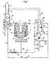
- la figure 1 est une vue schématique d'une installation selon l'invention;
- les figures 2 et 3 sont des schémas de deux variantes de réalisation de l'invention.
- En se référant à la figure 1, l'installation concerne une torche 1 à électrode 2 et tuyère 3 montée à coulissement dans le corps 4 de torche avec isolement par rapport à l'électrode 2. La torche 1 est ici représentée à faible distance d'une pièce à souder ou à couper 7. La source électrique d'alimentation de la torche 1 est un transformateur 10 dont un primaire monophasé 11 est raccordé, par deux conducteurs 12 et 13, à un réseau d'alimentation 14 via un interrupteur à commande automatique 15, qui peut d'ailleurs être placé en aval du transformateur 10. Un secondaire 16 alimente un pont redresseur 17 dont une borne négative 18 est branchée à l'électrode 2 de la torche 1 via un conducteur 19, tandis qu'une borne positive 20 est raccordée, par un conducteur 21, à une borne 22 d'une inductance 23 dont l'autre borne 24 est raccordée par un conducteur 25 à la pièce à traiter 7. Un circuit auxiliaire de commande 30 incorpore un transformateur très basse tension de sécurité 31 dont un primaire 32 est branché, via un interrupteur manuel 34, au réseau 14, en amont de l'interrupteur 15. Aux bornes d'un secondaire 33 du transformateur 31 sont branchés, en parallèle:
- - une lampe 40 d'indication de mise sous tension du circuit auxiliaire de commande 30,
- - un circuit de commande 41 comprenant un enroulement de commande 42 de l'interrupteur principal 15 en série avec un contact de relais 43,
- - un bobinage d'excitation 44 d'une électrovanne, non représentée, placée sur le conduit d'alimentation en gaz.
- Une borne 45 du secondaire 33 du transformateur 31 est également raccordée à la pièce 7 par un circuit incorporant en série un contact thermique 46, à ouverture en cas d'élévation anormale de température, placé dans les bobinages du transformateur principal 10, un contact 47 à fermeture sous l'effet d'une pression gazeuse, placé dans le conduit d'alimentation en gaz de la torche, un enroulement d'excitation 48, associé à une impédance 49 (condensateur 50 et résistance 51 en parallèle), cet enroulement 48 commandant, à l'état excité, la fermeture du contact 43, le tout étant branché, par un élément unidirectionnel 52, à la borne 24 de l'inductance 23, tandis que la borne négative 18 est branchée, par un élément unidirectionnel 53, à l'autre borne 54 du secondaire 33 du transformateur 31. D'autre part la borne 27 de l'inductance 23 est raccordée par un conducteur 55 à résistance 56 à la borne 45 du secondaire 33 du transformateur 31.
- Le fonctionnement de l'installation est le suivant: l'opérateur ferme l'interrupteur 34 du circuit auxiliaire 30 et ouvre le robinet d'alimentation général en gaz plasmagène, ce qui a pour effet de mettre sous tension le transformateur très basse tension 31, d'allumer la lampe témoin 40 et d'exciter l'enroulement 44 de l'électrovanne, de sorte que le gaz plasmagène parvient et s'écoule dans la torche 1, mais l'interrupteur principal 15 est encore en position d'ouverture.
- La formation de l'arc est assurée par la venue en contact mutuel de la tuyère 3 avec la pièce 7 et de l'électrode 2 avec la tuyère 3. Le circuit alimentant, à partir du transformateur 31, l'enroulement 48 est fermé, via les contacts de sécurité 46 et 47 et le court circuit 2-3-7, ce qui provoque la fermeture du contact 43 du relais 48, donc l'excitation du relais 42, donc la fermeture du contact 15 fermant l'interrupteur d'alimentation du transformateur principal 10. L'écartement de l'électrode 2 de la tuyère 3 forme l'arc de soudage ou coupage entre électrode 2 et pièce 7 et établit ainsi le courant de soudage ou coupage.
- Le maintien de l'excitation du relais 48 est assuré par la tension aux bornes 22-24 de l'inductance 22, qui dépend de l'existence du courant de soudage ou coupage, cette tension assurant l'alimentation du relais 48 via le conducteur 55, la résistance 56, les contacts de sécurité 46, 47 et l'élément unidirectionnel 52. Dès l'extinction de l'arc de soudage provoquée par l'opérateur, le relais 48 vient au repos, le contact 43 s'ouvre, le relais 42 vient au repos en ouvrant le contact 15.
- On note que l'arrêt de l'installation est obtenu, en outre, et indépendamment de l'opérateur, si la pression de gaz fait défaut (ouverture du contact 47) ou si le transformateur 10 s'échauffe anormalement (ouverture du contact 46). Un circuit de contrôle (lampe 60 et élément unidirectionnel 61) signale de façon optique l'état correct de l'alimentation gazeuse et le non-échauffement du transformateur 10. En outre, une lampe 62 branchée en série avec un élément unidirectionnel 63 signale optiquement le bon état du relais 42 et de son contact 15. De préférence la lampe 62 est en série avec un interrupteur à bilame 64, de sorte qu'en fonctionnement normal cette lampe 62 s'éclaire faiblement et s'éteint lors d'un arrêt de fonctionnement. Au contraire, la lampe 62 se mettra à clignoter au cas où le relais 42 (ou son contact 15) est défectueux, du fait de l'existence d'une tension à vide élevée aux bornes du secondaire 16 du transformateur 10. De préférence, on place un apparail sonore 65 en parallèle sur la lampe 62.
- En se référant à la figure 2, où l'on retrouve le transformateur principal 10, le redresseur 17, le circuit auxiliaire 30 à transformateur 31, ainsi que l'électrode 2, la tuyère 3 et la pièce 7, on note que le circuit de maintien du relais 42 est assuré, après amorçage, par un relais d'intensité 70 fermant un contact 71 en parallèle sur le contact 43.
- Selon la figure 3, le relais 48 commande directement le contact 15 et est monté en série avec un contact 75 d'un relais d'intensité 76, l'ensemble étant branché aux bornes de la source auxiliaire 31 d'une part, et, via une résistance 77 et l'élément unidirectionnel 53, aux bornes de l'ensemble électrode 2, tuyère 3, pièce 7 et relais d'intensité 76, d'autre part, de sorte que le contact 75 est d'abord fermé, grâce à l'alimentation du relais 76, par la source 31 lors du court-circuit 2-3-7, puis grâce à un courant de soudage, lorsque l'interrupteur 15 est fermé. L'invention s'applique au soudage ou au coupage, mettant en oeuvre un gaz d'arc, tel un gaz plasmagène.
Claims (8)
Priority Applications (1)
| Application Number | Priority Date | Filing Date | Title |
|---|---|---|---|
| AT85400618T ATE31261T1 (de) | 1984-04-04 | 1985-03-29 | Plasmaschneidegeraet mit sehr kleiner leistung. |
Applications Claiming Priority (2)
| Application Number | Priority Date | Filing Date | Title |
|---|---|---|---|
| FR8405285A FR2562453B1 (fr) | 1984-04-04 | 1984-04-04 | Equipement de coupage plasma de tres faible puissance |
| FR8405285 | 1984-04-04 |
Publications (2)
| Publication Number | Publication Date |
|---|---|
| EP0159256A1 EP0159256A1 (fr) | 1985-10-23 |
| EP0159256B1 true EP0159256B1 (fr) | 1987-12-09 |
Family
ID=9302820
Family Applications (1)
| Application Number | Title | Priority Date | Filing Date |
|---|---|---|---|
| EP85400618A Expired EP0159256B1 (fr) | 1984-04-04 | 1985-03-29 | Equipement de coupage plasma de très faible puissance |
Country Status (13)
| Country | Link |
|---|---|
| US (1) | US4598191A (fr) |
| EP (1) | EP0159256B1 (fr) |
| JP (1) | JPH0722829B2 (fr) |
| AT (1) | ATE31261T1 (fr) |
| AU (1) | AU574148B2 (fr) |
| BR (1) | BR8501582A (fr) |
| CA (1) | CA1244891A (fr) |
| DE (1) | DE3561135D1 (fr) |
| DK (1) | DK161748C (fr) |
| ES (1) | ES8607085A1 (fr) |
| FR (1) | FR2562453B1 (fr) |
| PT (1) | PT80216B (fr) |
| ZA (1) | ZA852284B (fr) |
Cited By (2)
| Publication number | Priority date | Publication date | Assignee | Title |
|---|---|---|---|---|
| US6841754B2 (en) | 2001-03-09 | 2005-01-11 | Hypertherm, Inc. | Composite electrode for a plasma arc torch |
| US9560732B2 (en) | 2006-09-13 | 2017-01-31 | Hypertherm, Inc. | High access consumables for a plasma arc cutting system |
Families Citing this family (26)
| Publication number | Priority date | Publication date | Assignee | Title |
|---|---|---|---|---|
| FR2578138B1 (fr) * | 1985-02-22 | 1987-03-27 | Soudure Autogene Francaise | Systeme de soudage ou de coupage plasma muni d'une temporisation |
| IT1204121B (it) * | 1986-02-27 | 1989-03-01 | Cebora Spa | Torcia di saldatura o taglio al plasma con arco non trasferito |
| US4780591A (en) * | 1986-06-13 | 1988-10-25 | The Perkin-Elmer Corporation | Plasma gun with adjustable cathode |
| IT1191365B (it) * | 1986-06-26 | 1988-03-16 | Cebora Spa | Circuito di comando per una apparecchiatura di talgio o saldatura al plasma ad arco trasferito |
| US4791268A (en) * | 1987-01-30 | 1988-12-13 | Hypertherm, Inc. | Arc plasma torch and method using contact starting |
| US4902871A (en) * | 1987-01-30 | 1990-02-20 | Hypertherm, Inc. | Apparatus and process for cooling a plasma arc electrode |
| US4803339A (en) * | 1987-09-16 | 1989-02-07 | Rockwell International Corporation | Hollow electrode and arc initiation method |
| FR2626206B1 (fr) * | 1988-01-25 | 1990-05-18 | Soudure Autogene Francaise | Torche et machine de travail a l'arc, et cartouche pour cette torche |
| US4918285A (en) * | 1988-06-09 | 1990-04-17 | Cyclomatic Industries, Inc. | System for supplying power |
| US4977305A (en) * | 1989-04-03 | 1990-12-11 | L-Tec Company | System for low voltage plasma arc cutting |
| JP2594649B2 (ja) * | 1989-09-29 | 1997-03-26 | 松下電器産業株式会社 | プラズマ切断または溶接用トーチ |
| IT1243170B (it) * | 1990-11-29 | 1994-05-24 | Trafimet Trafilerie Metalliche | Torcia per taglio al plasma con innesco per contatto |
| USRE37608E1 (en) * | 1991-04-08 | 2002-03-26 | Thermal Dynamics Corporation | Plasma torch electronic pulsing circuit |
| US5170030A (en) * | 1991-04-08 | 1992-12-08 | Thermal Dynamics Corporation | Plasma torch electronic pulsing circuit |
| US5208436A (en) * | 1991-04-12 | 1993-05-04 | The Lincoln Electric Company | Plasma torch with identification circuit |
| US5216221A (en) * | 1992-01-17 | 1993-06-01 | Esab Welding Products, Inc. | Plasma arc torch power disabling mechanism |
| US5530220A (en) * | 1994-04-11 | 1996-06-25 | Thermal Dynamics Corporation | Plasma torch arc transfer circuit |
| US6133543A (en) * | 1998-11-06 | 2000-10-17 | Hypertherm, Inc. | System and method for dual threshold sensing in a plasma ARC torch |
| US6969819B1 (en) * | 2004-05-18 | 2005-11-29 | The Esab Group, Inc. | Plasma arc torch |
| US8633416B2 (en) * | 2005-03-11 | 2014-01-21 | Perkinelmer Health Sciences, Inc. | Plasmas and methods of using them |
| US9662747B2 (en) | 2006-09-13 | 2017-05-30 | Hypertherm, Inc. | Composite consumables for a plasma arc torch |
| US10194516B2 (en) | 2006-09-13 | 2019-01-29 | Hypertherm, Inc. | High access consumables for a plasma arc cutting system |
| US10098217B2 (en) | 2012-07-19 | 2018-10-09 | Hypertherm, Inc. | Composite consumables for a plasma arc torch |
| US8258423B2 (en) * | 2009-08-10 | 2012-09-04 | The Esab Group, Inc. | Retract start plasma torch with reversible coolant flow |
| EP2716140B1 (fr) * | 2011-05-24 | 2017-07-12 | Victor Equipment Company | Torche à plasma d'arc possédant un circuit de démarrage secondaire et une électrode |
| US9945499B2 (en) | 2013-02-28 | 2018-04-17 | Showa Rasenkan Seisakusho Co., Ltd. | Method and apparatus for manufacturing interlocking pipe |
Family Cites Families (8)
| Publication number | Priority date | Publication date | Assignee | Title |
|---|---|---|---|---|
| DE1615352B2 (de) * | 1967-11-02 | 1971-09-02 | VEB Mansfeld Kombinat Wilhelm Pieck, χ 4250 Lutherstadt Eisleben | Schaltungsanordnung und vorrichtung fuer plasma handbrenner |
| FR2232395B1 (fr) * | 1973-06-06 | 1976-05-28 | Soudure Autogene Francaise | |
| US3997756A (en) * | 1974-06-21 | 1976-12-14 | David Grigorievich Bykhovsky | Method for striking main arc between the electrode of plasmatron and workpiece, and contrivance embodying same |
| DD132706A3 (de) * | 1974-10-08 | 1978-10-25 | Jochen Boehme | Verfahren und einrichtung zum schutz der duesen von werkstueckgepolten plasmabrennern |
| DE2803580C2 (de) * | 1978-01-27 | 1981-09-17 | Messer Griesheim Gmbh, 6000 Frankfurt | Einrichtung zum Plasmaschweißen und/ oder -schneiden |
| FR2447770A1 (fr) * | 1979-02-01 | 1980-08-29 | Air Liquide | Procede et installation de demarrage automatique d'une torche de coupage plasma |
| JPS5852745B2 (ja) * | 1979-04-10 | 1983-11-25 | トヨタ自動車株式会社 | プラズマア−ク起動装置 |
| JPS6430591A (en) * | 1987-07-24 | 1989-02-01 | Nok Corp | Introduction of mutagen to cell |
-
1984
- 1984-04-04 FR FR8405285A patent/FR2562453B1/fr not_active Expired
-
1985
- 1985-03-26 ZA ZA852284A patent/ZA852284B/xx unknown
- 1985-03-26 US US06/716,195 patent/US4598191A/en not_active Expired - Lifetime
- 1985-03-29 DE DE8585400618T patent/DE3561135D1/de not_active Expired
- 1985-03-29 AT AT85400618T patent/ATE31261T1/de not_active IP Right Cessation
- 1985-03-29 EP EP85400618A patent/EP0159256B1/fr not_active Expired
- 1985-04-01 AU AU40583/85A patent/AU574148B2/en not_active Ceased
- 1985-04-02 ES ES541853A patent/ES8607085A1/es not_active Expired
- 1985-04-03 PT PT80216A patent/PT80216B/pt not_active IP Right Cessation
- 1985-04-03 DK DK152685A patent/DK161748C/da not_active IP Right Cessation
- 1985-04-03 BR BR8501582A patent/BR8501582A/pt not_active IP Right Cessation
- 1985-04-03 CA CA000478336A patent/CA1244891A/fr not_active Expired
- 1985-04-04 JP JP60070135A patent/JPH0722829B2/ja not_active Expired - Lifetime
Cited By (4)
| Publication number | Priority date | Publication date | Assignee | Title |
|---|---|---|---|---|
| US6841754B2 (en) | 2001-03-09 | 2005-01-11 | Hypertherm, Inc. | Composite electrode for a plasma arc torch |
| US7659488B2 (en) | 2001-03-09 | 2010-02-09 | Hypertherm, Inc. | Composite electrode for a plasma arc torch |
| USRE46925E1 (en) | 2001-03-09 | 2018-06-26 | Hypertherm, Inc. | Composite electrode for a plasma arc torch |
| US9560732B2 (en) | 2006-09-13 | 2017-01-31 | Hypertherm, Inc. | High access consumables for a plasma arc cutting system |
Also Published As
| Publication number | Publication date |
|---|---|
| ZA852284B (en) | 1985-11-27 |
| AU4058385A (en) | 1985-10-10 |
| DK152685A (da) | 1985-10-05 |
| ES8607085A1 (es) | 1986-05-16 |
| PT80216B (pt) | 1987-08-19 |
| JPH0722829B2 (ja) | 1995-03-15 |
| DK152685D0 (da) | 1985-04-03 |
| AU574148B2 (en) | 1988-06-30 |
| FR2562453A1 (fr) | 1985-10-11 |
| FR2562453B1 (fr) | 1988-02-26 |
| US4598191A (en) | 1986-07-01 |
| JPS60221176A (ja) | 1985-11-05 |
| ATE31261T1 (de) | 1987-12-15 |
| CA1244891A (fr) | 1988-11-15 |
| DK161748C (da) | 1992-02-03 |
| DK161748B (da) | 1991-08-12 |
| EP0159256A1 (fr) | 1985-10-23 |
| DE3561135D1 (en) | 1988-01-21 |
| PT80216A (fr) | 1985-05-01 |
| ES541853A0 (es) | 1986-05-16 |
| BR8501582A (pt) | 1985-12-03 |
Similar Documents
| Publication | Publication Date | Title |
|---|---|---|
| CA1244891A (fr) | Equipement de coupage plasma de tres faible puissance | |
| CA1137563A (fr) | Procede et installation de demarrage automatique d'une torche de coupage plasma | |
| EP0192573B1 (fr) | Système de soudage ou de coupage plasma muni d'une temporisation | |
| US5866868A (en) | Spot welding apparatus | |
| US4073611A (en) | Control system for gas burning apparatus | |
| EP0109891B1 (fr) | Dispositif d'amorçage par haute fréquence et électrode auxiliaire d'un arc électrique de soudage ou de coupage | |
| EP0819494B1 (fr) | Alimentation électrique pour soudage | |
| EP0020280A1 (fr) | Dispositif d'allumage de sécurité destiné à une valve pour brûleur | |
| US4996463A (en) | Auxiliary lighting system for high intensity discharge lamp | |
| CN1326656C (zh) | 焊机及其采用的电磁开关 | |
| US4099095A (en) | Operating circuit for gaseous discharge and incandescent lamps | |
| EP0439417B1 (fr) | Dispositif de sécurité pour le fonctionnement d'un brûleur | |
| JP2555605B2 (ja) | プラズマア−ク切断装置 | |
| CA1114473A (fr) | Systeme d'allumage de securite pour bruleur | |
| FR2583856A1 (fr) | Circuit de coupure temporisee d'un bruleur a gaz | |
| US3673464A (en) | Energization system with safety provision for faulty rectifier | |
| CA1228896A (fr) | Systeme de soudage aux electrodes refractaires en atmosphere inerte, dit tig | |
| FR2672529A1 (fr) | Procede et dispositif pour l'allumage et l'amorcage d'une reaction d'oxycoupage ou de decriquage. | |
| JPH0671670B2 (ja) | 酸素プラズマ切断方法 | |
| BE524027A (fr) | ||
| BE510413A (fr) | ||
| FR2468098A1 (fr) | Circuit de commande pour dispositifs pyrotechniques | |
| JPH0633398U (ja) | 放電灯点灯装置 | |
| FR2492557A1 (fr) | Montage pour la regulation de l'amenee de courant a un dispositif de coupe electrothermique | |
| FR2465954A3 (fr) | Controleur automatique de flamme alimente par une tension alternative |
Legal Events
| Date | Code | Title | Description |
|---|---|---|---|
| PUAI | Public reference made under article 153(3) epc to a published international application that has entered the european phase |
Free format text: ORIGINAL CODE: 0009012 |
|
| 17P | Request for examination filed |
Effective date: 19850404 |
|
| AK | Designated contracting states |
Designated state(s): AT BE CH DE FR GB IT LI LU NL SE |
|
| 17Q | First examination report despatched |
Effective date: 19861001 |
|
| ITF | It: translation for a ep patent filed | ||
| GRAA | (expected) grant |
Free format text: ORIGINAL CODE: 0009210 |
|
| AK | Designated contracting states |
Kind code of ref document: B1 Designated state(s): AT BE CH DE FR GB IT LI LU NL SE |
|
| REF | Corresponds to: |
Ref document number: 31261 Country of ref document: AT Date of ref document: 19871215 Kind code of ref document: T |
|
| REF | Corresponds to: |
Ref document number: 3561135 Country of ref document: DE Date of ref document: 19880121 |
|
| GBT | Gb: translation of ep patent filed (gb section 77(6)(a)/1977) | ||
| PLBE | No opposition filed within time limit |
Free format text: ORIGINAL CODE: 0009261 |
|
| STAA | Information on the status of an ep patent application or granted ep patent |
Free format text: STATUS: NO OPPOSITION FILED WITHIN TIME LIMIT |
|
| 26N | No opposition filed | ||
| ITTA | It: last paid annual fee | ||
| EPTA | Lu: last paid annual fee | ||
| EAL | Se: european patent in force in sweden |
Ref document number: 85400618.6 |
|
| PGFP | Annual fee paid to national office [announced via postgrant information from national office to epo] |
Ref country code: SE Payment date: 19980217 Year of fee payment: 14 |
|
| PGFP | Annual fee paid to national office [announced via postgrant information from national office to epo] |
Ref country code: CH Payment date: 19980226 Year of fee payment: 14 |
|
| PGFP | Annual fee paid to national office [announced via postgrant information from national office to epo] |
Ref country code: NL Payment date: 19980228 Year of fee payment: 14 |
|
| PGFP | Annual fee paid to national office [announced via postgrant information from national office to epo] |
Ref country code: LU Payment date: 19980302 Year of fee payment: 14 |
|
| PGFP | Annual fee paid to national office [announced via postgrant information from national office to epo] |
Ref country code: FR Payment date: 19990208 Year of fee payment: 15 |
|
| PGFP | Annual fee paid to national office [announced via postgrant information from national office to epo] |
Ref country code: AT Payment date: 19990210 Year of fee payment: 15 |
|
| PGFP | Annual fee paid to national office [announced via postgrant information from national office to epo] |
Ref country code: GB Payment date: 19990216 Year of fee payment: 15 |
|
| PGFP | Annual fee paid to national office [announced via postgrant information from national office to epo] |
Ref country code: DE Payment date: 19990226 Year of fee payment: 15 |
|
| PGFP | Annual fee paid to national office [announced via postgrant information from national office to epo] |
Ref country code: BE Payment date: 19990302 Year of fee payment: 15 |
|
| PG25 | Lapsed in a contracting state [announced via postgrant information from national office to epo] |
Ref country code: LU Free format text: LAPSE BECAUSE OF NON-PAYMENT OF DUE FEES Effective date: 19990329 |
|
| PG25 | Lapsed in a contracting state [announced via postgrant information from national office to epo] |
Ref country code: SE Free format text: LAPSE BECAUSE OF NON-PAYMENT OF DUE FEES Effective date: 19990330 |
|
| PG25 | Lapsed in a contracting state [announced via postgrant information from national office to epo] |
Ref country code: LI Free format text: LAPSE BECAUSE OF NON-PAYMENT OF DUE FEES Effective date: 19990331 Ref country code: CH Free format text: LAPSE BECAUSE OF NON-PAYMENT OF DUE FEES Effective date: 19990331 |
|
| PG25 | Lapsed in a contracting state [announced via postgrant information from national office to epo] |
Ref country code: NL Free format text: LAPSE BECAUSE OF NON-PAYMENT OF DUE FEES Effective date: 19991001 |
|
| EUG | Se: european patent has lapsed |
Ref document number: 85400618.6 |
|
| REG | Reference to a national code |
Ref country code: CH Ref legal event code: PL |
|
| NLV4 | Nl: lapsed or anulled due to non-payment of the annual fee |
Effective date: 19991001 |
|
| EUG | Se: european patent has lapsed |
Ref document number: 85400618.6 |
|
| PG25 | Lapsed in a contracting state [announced via postgrant information from national office to epo] |
Ref country code: GB Free format text: LAPSE BECAUSE OF NON-PAYMENT OF DUE FEES Effective date: 20000329 Ref country code: AT Free format text: LAPSE BECAUSE OF NON-PAYMENT OF DUE FEES Effective date: 20000329 |
|
| PG25 | Lapsed in a contracting state [announced via postgrant information from national office to epo] |
Ref country code: BE Free format text: LAPSE BECAUSE OF NON-PAYMENT OF DUE FEES Effective date: 20000331 |
|
| BERE | Be: lapsed |
Owner name: LA SOUDURE AUTOGENE FRANCAISE Effective date: 20000331 |
|
| GBPC | Gb: european patent ceased through non-payment of renewal fee |
Effective date: 20000329 |
|
| PG25 | Lapsed in a contracting state [announced via postgrant information from national office to epo] |
Ref country code: FR Free format text: LAPSE BECAUSE OF NON-PAYMENT OF DUE FEES Effective date: 20001130 |
|
| REG | Reference to a national code |
Ref country code: FR Ref legal event code: ST |
|
| PG25 | Lapsed in a contracting state [announced via postgrant information from national office to epo] |
Ref country code: DE Free format text: LAPSE BECAUSE OF NON-PAYMENT OF DUE FEES Effective date: 20010103 |