EP0159301B1 - Elektronisch gesteuerte Gruppenantenne mit reduzierten Nebenkeulen - Google Patents
Elektronisch gesteuerte Gruppenantenne mit reduzierten Nebenkeulen Download PDFInfo
- Publication number
- EP0159301B1 EP0159301B1 EP19850850105 EP85850105A EP0159301B1 EP 0159301 B1 EP0159301 B1 EP 0159301B1 EP 19850850105 EP19850850105 EP 19850850105 EP 85850105 A EP85850105 A EP 85850105A EP 0159301 B1 EP0159301 B1 EP 0159301B1
- Authority
- EP
- European Patent Office
- Prior art keywords
- waveguides
- slits
- wave guide
- antenna
- wave
- Prior art date
- Legal status (The legal status is an assumption and is not a legal conclusion. Google has not performed a legal analysis and makes no representation as to the accuracy of the status listed.)
- Expired
Links
- 230000010363 phase shift Effects 0.000 claims 1
- 230000005855 radiation Effects 0.000 description 10
- 238000010586 diagram Methods 0.000 description 8
- 230000005672 electromagnetic field Effects 0.000 description 2
- 238000003491 array Methods 0.000 description 1
- 238000004364 calculation method Methods 0.000 description 1
- 238000010276 construction Methods 0.000 description 1
- 230000008878 coupling Effects 0.000 description 1
- 238000010168 coupling process Methods 0.000 description 1
- 238000005859 coupling reaction Methods 0.000 description 1
- 230000000694 effects Effects 0.000 description 1
- 238000005286 illumination Methods 0.000 description 1
- 238000004519 manufacturing process Methods 0.000 description 1
- 230000001629 suppression Effects 0.000 description 1
Images

Classifications
-
- H—ELECTRICITY
- H01—ELECTRIC ELEMENTS
- H01Q—ANTENNAS, i.e. RADIO AERIALS
- H01Q21/00—Antenna arrays or systems
- H01Q21/06—Arrays of individually energised antenna units similarly polarised and spaced apart
- H01Q21/22—Antenna units of the array energised non-uniformly in amplitude or phase, e.g. tapered array or binomial array
-
- H—ELECTRICITY
- H01—ELECTRIC ELEMENTS
- H01Q—ANTENNAS, i.e. RADIO AERIALS
- H01Q21/00—Antenna arrays or systems
- H01Q21/0006—Particular feeding systems
- H01Q21/0037—Particular feeding systems linear waveguide fed arrays
- H01Q21/0043—Slotted waveguides
- H01Q21/005—Slotted waveguides arrays
Definitions
- the present invention relates to an electrically controlled antenna array, i.e. an antenna with a main lobe which may be controlled by varying the phases in the included antenna elements.
- an antenna is used in radar reconnaissance equipment for example.
- An antenna array of the kind intended here comprises a plurality of antenna elements configured as rectangular wave guides lying parallel.
- the radiation openings in the elements are formed as so-called broad side slits, i.e. longitudinal slits along the wider surface of each wave guide in the antenna array.
- the antenna lobe controllable in a plane at right angles to the longitudinal direction of the wave guides by placing phase shifters in the feed path to each guide, e.g. according to GB-B1.577.939. alternatingly above and below the centre line of the wave guides, the illumination function will be phase modulated along the antenna aperture, i.e. along the wave guides. This gives rise to large side lobe peaks in the antenna array radiation diagram.
- edge slits may be used instead of broadside slits, see “Low-Sidelobe Radar Antennas” by H. E. Schrank from “Microwave Journal", July 1983 p 109 ff. Edge slits are difficult to master from the electrical design aspect, particularly due to the strong electromagnetic coupling between them, and it is therefore desirable to retain broadside slits to obtain good side lobe suppression.
- a slot array antenna with slotted wave guides is previously known from US-A-4.423.421. This antenna is not provided with adjustable phase shifters to vary the phase of the electromagnetic field to the wave guides in the array.
- the spacing between the slots in one wave guide is different from that of another wave guide in order to produce a symmetrical pencil beam with maximized antenna gain and reduced sidelobes, but the pencil beam has a constant lobe direction.
- the object of the present invention is to achieve an electrically controlled antenna array of the kind mentioned in the introduction, using broadside slits as radiation elements, the antenna diagram of which shows substantially suppressed side lobes.
- the invention is characterized as will be seen from the characterizing portion of claim 1.
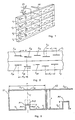
- the antenna array in Figure 1 comprises a plurality of antenna elements (4 elements in the Figure) in the form of rectangularwave guides V1, V2, V3 and V4 lying parallel along their respective long narrow sides.
- Feed wave guides M1 and M2-M4 are each connected to one of the wave guides Vl-V4.
- Each wave guide is provided with radiation openings in the form of longitudinal slits, S 11 , S 12 ,... on the wave guide V1, S 21 , S 22 on the wave guide V2, S 31 , S 32 , ... on the wave guide V3 and S 41 , S 42 , ... on the wave guide V4. All the slits or slots shown are so-called broadside slits, i.e.
- the end portions of the feed wave guides Ml-M4 which are attached to the wave guides V1V4 have a feed opening (not illustrated in Figure 1) through which electromagnetic field energy, e.g. within the X band, is fed to each wave guide V1V4.
- the other ends of the feed wave guides are connected via suitable input feed elements to the phase shifters F1 ⁇ F4 (F3 and F4 being concealed in Figure 1) for controlling the phase of the field fed in, relative to a reference phase, e.g. the phase of the field to the wave guide VI.
- the grid lobes from the individual wave guides V1 ⁇ V4 would occur at different places in the radiation diagram and would not be added to each other to form the prominent peaks (S 1 , S 2 ) in Figure 4.
- different element spacing is achieved by changing the wavelength of the individual wave guides.
- Figure 2 illustrates a portion of the antenna array in Figure 1, portions of two wave guides being depicted.
- the slits S 11' S 12 , and S 13 , S 14 in the wave guide V1 have the mutual spacing d 1 and the slits S 21 , S 22 , S 23 , S 24 etc in the wave guide V2 have the mutual spacing d 2 ⁇ d 1 .
- the wave guide wavelength ⁇ g varied such that ⁇ g is different for each of the guides V1 ⁇ V4. This is described below in connection with Figure 3.
- Different spacings d 1 , d 2 between the slits of the different wave guides V1 ⁇ V4 are obtained as a consequence.
- FIG 3 is a cross section of a wave guide VI with the slits S 11 , S 12 , there also being shown a part of an adjacent wave guide V2.
- the wave guide VI On its inner surface facing the slits S 11 , S 12 the wave guide VI is provided with a raised portion or ridge R1, situated symmetrically about the symmetrical axis C of the wave guide.
- the ridge has two side walls RV1 and RV2 extending at right angles to the inner surface Y of the wave guide in the longitudinal direction and entire length thereof.
- the side walls RV1 and RV2 are bridged by a wall RV3 at right angles to them. Both walls RV1 and RV2 have a height h 1 from the surface Y.
- the wave guide V1 is a so-called ridge wave guide wherein the wavelength ⁇ g for a given wave guide width a and height b may be varied within given limits by varying the ridge height h 1 .
- the height h 1 is thus constant for a given wave guide in the group antenna, i.e. for the wave guide VI the height of the ridge R1 is equal to h,, for the wave guide V2 the height of the ridge R2 is h 2 (h1 ⁇ h2) and so on. Since the slit spacing d ⁇ g/2, the grating lobes may be spread out over the lobe angle interval of the antenna, thereby reducing their effect on the side lobe level.
- Figure 5 a radiation diagram for an antenna array with a ridge wave guide where this principle is utilised.
- the diagram in Figure 5 may be compared directly with the one in Figure 4, since apart from the ridges R1, R2 the antennas are otherwise entirely the same.
- the inventive antenna array retains the above- mentioned advantages due to the broadside slits, but with reduced side lobes.
- the invention is not restricted to embrace wave guides V1 ⁇ V4, where the wave guide wavelengths ⁇ g 1 , ⁇ g 2 , ... for the different wave guides have been varied by the measures described in connection with Figure 3.
- What is essential in the inventive concept is that the wavelengths ⁇ g 1 , ⁇ g 2 ... have been made different, which results in that the mutual spacing d 1 , d 2 , ... must be dimensioned so that d1 ⁇ d2 etc.
- d1 ⁇ d2 etc There is thus obtained variation in the positions of the grating lobes for the entire antenna array, which causes a reduction of the side lobe level.
Landscapes
- Waveguide Aerials (AREA)
- Variable-Direction Aerials And Aerial Arrays (AREA)
Claims (1)
- Elektronisch gesteuerte Gruppenantenne mit zumindest zwei nebeneinandergestellten Antennenelementen, die ein Hauptstrahlungskeulenrichtung in Abhängigkeit von der relativen Phasenverschiebung der elektrischen Signale ergibt, die den entsprechenden rechteckigen Wellenleitern (V1, V2,...) zugeführt werden, die die nebeneinandergestellten Antennenelemente bilden, wobei eine Breitseitenoberfläche der Wellenleiter mit mehreren Strahleröffnungen in Form von Spalten oder Schlitzen (S11, S12, ... S21, S22, ...) in Längsrichtung ausgestattet sind, wobei die Wellenleiter derart implementiert sind, daß die Wellenleiterwellenlänge (λg) für zumindest einige der Wellenleiter (V1, V2, ...) wechselseitig unterschiedliche Werte annimmt und die wechselseitigen Abstände (di, d2, ...) der Querseitenspalte oder -schlitze für ausgewählte Wellenleiter unterschiedlich sind, dadurch gekennzeichnet, daßa) die Wellenleiter (V1, V2, ...) im wesentlichen die gleiche Länge und Breite aufweisen, undb) die unterschiedlichen Werte der Wellenleiterwellenlängen (λg) derart ausgewählt sind, daß die Gitterstrahlungskeulen, die zu den einzelnen Antennenelementen gehören, gestreut werden.
Applications Claiming Priority (2)
| Application Number | Priority Date | Filing Date | Title |
|---|---|---|---|
| SE8402140A SE442074B (sv) | 1984-04-17 | 1984-04-17 | Elektriskt styrd gruppantenn med reducerade sidolober |
| SE8402140 | 1984-04-17 |
Publications (2)
| Publication Number | Publication Date |
|---|---|
| EP0159301A1 EP0159301A1 (de) | 1985-10-23 |
| EP0159301B1 true EP0159301B1 (de) | 1989-06-07 |
Family
ID=20355609
Family Applications (1)
| Application Number | Title | Priority Date | Filing Date |
|---|---|---|---|
| EP19850850105 Expired EP0159301B1 (de) | 1984-04-17 | 1985-03-26 | Elektronisch gesteuerte Gruppenantenne mit reduzierten Nebenkeulen |
Country Status (3)
| Country | Link |
|---|---|
| EP (1) | EP0159301B1 (de) |
| DE (1) | DE3570953D1 (de) |
| SE (1) | SE442074B (de) |
Families Citing this family (9)
| Publication number | Priority date | Publication date | Assignee | Title |
|---|---|---|---|---|
| SE449540B (sv) * | 1985-10-31 | 1987-05-04 | Ericsson Telefon Ab L M | Vagledarelement for en elektriskt styrd radarantenn |
| US4821044A (en) * | 1987-04-14 | 1989-04-11 | Hughes Aircraft Company | Waveguide slot array termination and antenna system |
| FR2622055B1 (fr) * | 1987-09-09 | 1990-04-13 | Bretagne Ctre Regl Innova Tran | Antenne plaque microonde, notamment pour radar doppler |
| DE3915048A1 (de) * | 1989-05-08 | 1990-11-15 | Siemens Ag | Elektronisch phasengesteuerte antennenanordnung |
| DE4105764A1 (de) * | 1991-02-23 | 1992-08-27 | Standard Elektrik Lorenz Ag | Vorrichtung zur formung eines antennendiagrammes bei einer hohlleiterschlitzarrayantenne mit serienspeisung |
| DE4201933C2 (de) * | 1992-01-24 | 1996-04-04 | Siemens Ag | Strahlergruppenantenne |
| EP1690318B1 (de) * | 2003-11-27 | 2013-01-02 | Telefonaktiebolaget LM Ericsson (publ) | Scannbare dünn besiedelte gruppenantenne |
| US10263331B2 (en) * | 2014-10-06 | 2019-04-16 | Kymeta Corporation | Device, system and method to mitigate side lobes with an antenna array |
| WO2018145300A1 (zh) | 2017-02-10 | 2018-08-16 | 华为技术有限公司 | 一种天线阵列及通信设备 |
Family Cites Families (3)
| Publication number | Priority date | Publication date | Assignee | Title |
|---|---|---|---|---|
| US3193830A (en) * | 1963-07-25 | 1965-07-06 | Joseph H Provencher | Multifrequency dual ridge waveguide slot antenna |
| US3524189A (en) * | 1966-11-09 | 1970-08-11 | Us Army | Slotted waveguide antenna array providing dual frequency operation |
| US4423421A (en) * | 1979-11-26 | 1983-12-27 | Raytheon Company | Slot array antenna with amplitude taper across a small circular aperture |
-
1984
- 1984-04-17 SE SE8402140A patent/SE442074B/sv not_active IP Right Cessation
-
1985
- 1985-03-26 EP EP19850850105 patent/EP0159301B1/de not_active Expired
- 1985-03-26 DE DE8585850105T patent/DE3570953D1/de not_active Expired
Also Published As
| Publication number | Publication date |
|---|---|
| EP0159301A1 (de) | 1985-10-23 |
| SE8402140L (sv) | 1985-10-18 |
| SE8402140D0 (sv) | 1984-04-17 |
| DE3570953D1 (en) | 1989-07-13 |
| SE442074B (sv) | 1985-11-25 |
Similar Documents
| Publication | Publication Date | Title |
|---|---|---|
| DE69014607T2 (de) | Gruppenantennen. | |
| DE3486164T2 (de) | Resonanzhohlleiterschalter für strahlende Öffnung. | |
| DE68919419T2 (de) | Antenne mit geschlitztem Hohlleiter. | |
| DE68910677T2 (de) | Mikrostreifenantenne. | |
| US5359338A (en) | Linear conformal antenna array for scanning near end-fire in one direction | |
| US3729740A (en) | Vehicle antenna for vehicular communication system using leaky coaxial cable | |
| US5039994A (en) | Dipole arrays | |
| RU2107974C1 (ru) | Фидерная система для электромагнитного сигнала и антенна (варианты) | |
| DE69627599T2 (de) | Abstrahlendes Koaxialkabel und Funkübertragungssystem mit einem derartigen Kabel | |
| US2840818A (en) | Slotted antenna | |
| EP0531800A1 (de) | Asymmetrischer, glockenförmiger Schlitzstrahler | |
| US4423392A (en) | Dual-mode stripline antenna feed performing multiple angularly separated beams in space | |
| US4238798A (en) | Stripline antennae | |
| DE3827956A1 (de) | Schlitzantenne | |
| US5650793A (en) | Centered longitudinal series/series coupling slot for coupling energy between a boxed stripline and a crossed rectangular waveguide and antenna array employing same | |
| DE69927637T2 (de) | Boxhorn-Gruppenanordnung mit gefalteten Verzweigungen | |
| US4409595A (en) | Stripline slot array | |
| US3977006A (en) | Compensated traveling wave slotted waveguide feed for cophasal arrays | |
| CN114566795B (zh) | 一种平顶方向图毫米波雷达天线及系统 | |
| US4788552A (en) | Wave guide element for an electrically controlled radar antenna | |
| EP0159301A1 (de) | Elektronisch gesteuerte Gruppenantenne mit reduzierten Nebenkeulen | |
| US3523297A (en) | Dual frequency antenna | |
| DE4013934A1 (de) | Flacher schlitzgruppenstrahler fuer te-modus-welle | |
| US4507664A (en) | Dielectric image waveguide antenna array | |
| US4241353A (en) | Multimode monopulse feed and antenna incorporating same |
Legal Events
| Date | Code | Title | Description |
|---|---|---|---|
| PUAI | Public reference made under article 153(3) epc to a published international application that has entered the european phase |
Free format text: ORIGINAL CODE: 0009012 |
|
| AK | Designated contracting states |
Designated state(s): CH DE FR GB IT LI NL |
|
| 17P | Request for examination filed |
Effective date: 19851218 |
|
| 17Q | First examination report despatched |
Effective date: 19870907 |
|
| GRAA | (expected) grant |
Free format text: ORIGINAL CODE: 0009210 |
|
| ITF | It: translation for a ep patent filed | ||
| AK | Designated contracting states |
Kind code of ref document: B1 Designated state(s): CH DE FR GB IT LI NL |
|
| REF | Corresponds to: |
Ref document number: 3570953 Country of ref document: DE Date of ref document: 19890713 |
|
| ET | Fr: translation filed | ||
| PLBE | No opposition filed within time limit |
Free format text: ORIGINAL CODE: 0009261 |
|
| STAA | Information on the status of an ep patent application or granted ep patent |
Free format text: STATUS: NO OPPOSITION FILED WITHIN TIME LIMIT |
|
| 26N | No opposition filed | ||
| ITTA | It: last paid annual fee | ||
| REG | Reference to a national code |
Ref country code: GB Ref legal event code: IF02 |
|
| PGFP | Annual fee paid to national office [announced via postgrant information from national office to epo] |
Ref country code: NL Payment date: 20040229 Year of fee payment: 20 |
|
| PGFP | Annual fee paid to national office [announced via postgrant information from national office to epo] |
Ref country code: GB Payment date: 20040317 Year of fee payment: 20 |
|
| PGFP | Annual fee paid to national office [announced via postgrant information from national office to epo] |
Ref country code: FR Payment date: 20040318 Year of fee payment: 20 |
|
| PGFP | Annual fee paid to national office [announced via postgrant information from national office to epo] |
Ref country code: CH Payment date: 20040322 Year of fee payment: 20 |
|
| PGFP | Annual fee paid to national office [announced via postgrant information from national office to epo] |
Ref country code: DE Payment date: 20040430 Year of fee payment: 20 |
|
| PG25 | Lapsed in a contracting state [announced via postgrant information from national office to epo] |
Ref country code: LI Free format text: LAPSE BECAUSE OF EXPIRATION OF PROTECTION Effective date: 20050325 Ref country code: GB Free format text: LAPSE BECAUSE OF EXPIRATION OF PROTECTION Effective date: 20050325 Ref country code: CH Free format text: LAPSE BECAUSE OF EXPIRATION OF PROTECTION Effective date: 20050325 |
|
| PG25 | Lapsed in a contracting state [announced via postgrant information from national office to epo] |
Ref country code: NL Free format text: LAPSE BECAUSE OF EXPIRATION OF PROTECTION Effective date: 20050326 |
|
| REG | Reference to a national code |
Ref country code: GB Ref legal event code: PE20 |
|
| REG | Reference to a national code |
Ref country code: CH Ref legal event code: PL |
|
| NLV7 | Nl: ceased due to reaching the maximum lifetime of a patent |
Effective date: 20050326 |