EP0159437A2 - Voiture-jouet à treuil de halage, télécommandée - Google Patents
Voiture-jouet à treuil de halage, télécommandée Download PDFInfo
- Publication number
- EP0159437A2 EP0159437A2 EP84307266A EP84307266A EP0159437A2 EP 0159437 A2 EP0159437 A2 EP 0159437A2 EP 84307266 A EP84307266 A EP 84307266A EP 84307266 A EP84307266 A EP 84307266A EP 0159437 A2 EP0159437 A2 EP 0159437A2
- Authority
- EP
- European Patent Office
- Prior art keywords
- electric motor
- toy vehicle
- winch
- gear
- remote
- Prior art date
- Legal status (The legal status is an assumption and is not a legal conclusion. Google has not performed a legal analysis and makes no representation as to the accuracy of the status listed.)
- Granted
Links
Images

Classifications
-
- A—HUMAN NECESSITIES
- A63—SPORTS; GAMES; AMUSEMENTS
- A63H—TOYS, e.g. TOPS, DOLLS, HOOPS OR BUILDING BLOCKS
- A63H17/00—Toy vehicles, e.g. with self-drive; ; Cranes, winches or the like; Accessories therefor
- A63H17/12—Toy vehicles, e.g. with self-drive; ; Cranes, winches or the like; Accessories therefor with cranes, winches or the like
-
- A—HUMAN NECESSITIES
- A63—SPORTS; GAMES; AMUSEMENTS
- A63H—TOYS, e.g. TOPS, DOLLS, HOOPS OR BUILDING BLOCKS
- A63H30/00—Remote-control arrangements specially adapted for toys, e.g. for toy vehicles
- A63H30/02—Electrical arrangements
- A63H30/04—Electrical arrangements using wireless transmission
Definitions
- This invention relates to a remote-controllable toy vehicle, particularly a radio controlled toy vehicle, with a winch mechanism.
- the invention seeks to provide a remote-controllable toy vehicle with a winch mechanism, which mitigates the aforesaid drawbacks.
- a remote-controllable toy vehicle comprising driving wheels, a winch mechanism, a first electric motor for driving and controlling the driving wheels, a second electric motor for controlling the winch mechanism, and a change-over switch for switching a power circuit for said electric motors.
- a common controller for operating the first and second electric motors in forward or reverse rotation and discontinuation.
- the controller is a radio transmitter and a radio-receiver is provided on the vehicle.
- the second electric motor is connected via reduction gearing to a winch drum, and idling means are provided between the second electric motor and the reduction gearing for preventing overload of the second electric motor when the winch drum ceases to rotate at the end of winch operation.
- the idling means conveniently, comprises a gear mounted on an output shaft of the second electric motor for rotation relative thereto and urged by spring means into frictional engagement with a shoulder fixed to the output shaft.
- a final gear of the reduction gearing and the winch drum are mounted on a common shaft and have mutually engageable driving and driven elements, respectively, which elements can be manually disengaged by displacing the common shaft axially against the force of spring means.
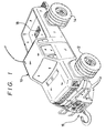
- the remote-controllable toy vehicle shown therein is radio controlled and comprises a body 10 provided at its front and rear ends with respective pairs of driving wheels 12, 14 while a winch mechanism 16 is mounted beneath a front bumper. Further, a rear platform of the vehicle body 10 is provided with a switch 18 for switching between the running and the winching operations.
- Two electric motors 20, 22 which are independently controlled, are provided to drive the wheels 12, 14 and the winch mechanism 16, respectively.
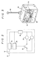
- a basic construction of an electric control circuit for the motors 20, 22 is shown in Figure 2. As shown in Figure 2, the motors 20, 22 are connected in parallel to a power circuit comprising a radio-receiver 24, a motor-driving circuit 26 and a battery 28, whereby the switch 18 can energise either one of the motors 20, 22.
- a conventional radio-transmitter 30 (see Figure 3) is used to operate the power circuit 26.
- the transmitter 30 is provided with a lever 32 for controlling rotation of the motor and a lever 34 for controlling a steering operation of the vehicle.
- reference 36 represents a power switch while reference 38 represents a transmitter aerial.
- the lever 32 of the transmitter 30 may be operated to move the vehicle forwards or in reverse or to bring the vehicle to a standstill, while the lever 34 controls the direction in which the vehicle is steered.
- the lever 32 may be operated to control the winding and unwinding operation of the winch mechanism, as well as its discontinuation.
- the winch mechanism 16 shown therein comprises a winch drum 40, to which a given rotary driving force is transmitted from an output shaft of the electric motor 22 via a reduction gear mechanism.
- a winch drum 40 To the winch drum 40 is secured one end of a winch rope 42 having a given length, while the other end of the rope 42 is provided with a hook 44, so that the rope 42 can be wound on or unwound from the winch drum 40.
- the reduction gear mechanism transmitting driving force from the output shaft of the motor 22 to the winch drum 40 is constructed in the following manner.
- a first gear 46 is mounted on the shaft 22 for rotation relative thereto between a pair of shoulders 48 and 50, fixed to the output shaft.
- the gear 46 is urged into frictional engagement with the shoulder 48 by a spring 52 acting between the gear 46 and the shoulder 50 such that under an overload condition caused when the winch ceases to rotate the gear 46 also ceases to rotate while the motor 22 continues to rotate. This prevents damage to the motor.
- the first gear 46 is in mesh with a second large gear 54 rotatable with a coaxial second small gear 56 which in turn is in mesh with a third large gear 58.
- the gear 58 is rotatably and coaxially arranged with a third small gear 60, a fourth gear 62 and a fifth gear 64.
- the gear 64 in turn is in mesh with a sixth gear 68 supported on a shaft 66 on which the winch drum 40 is freely rotatable.
- Opposing faces of the sixth gear 68 and the winch drum 40 are provided with respective driving and driven elements 70, 72 which may be coupled in the rotating direction.
- the shaft 66 On the side of the winch drum 40 remote from the gear 68, the shaft 66 supports a seventh large gear and a seventh small gear in mesh respectively with the third small gear 60 and the fourth gear 62 for stabilizing the latter gears.
- One end of the shaft 66 projects beyond the sixth gear 68 and is supported in a wall of a housing 80 of the winch mechanism 16, while the opposite end of the shaft 66 is projects outwards from the housing 80 and is covered with a cap 82.
- a compression spring 78 is mounted about the shaft 66 and interposed between the gear 68 and the wall of the housing 80.
- the driving and driven elements 70 and 72 may be disengaged from one another by manually displacing the shaft 66 and with it the gear 68 in an axial direction, against the force of the spring 78, so that the winch rope 42 can be smoothly withdrawn from the drum 40.
- the radio-controllable toy vehicle with the aforesaid winch drum is provided with separate electric motors 20 and 22 for the driving wheels and for the winch mechanism, while the switch 18 is provided for switching the power circuit connected to the electric motors, so that the single combination of the radio transmitter 30 and receiver 24 may be used to achieve the running and the winching operations conveniently and smoothly.
- a separate motor for the winching operation is provided, so that any gear-transmission mechanism for the running operation may be omitted, resulting in simple and strong construction.
- an idling mechanism as a means for preventing the overload may be mounted directly on the output shaft of the electric motor to protect the latter conveniently.
- the winch drum is releasably coupled with the reduction gear mechanism, so that the winch drum may be disengaged from the reduction gear mechanism with external operation to allow free rotation of the winch drum and hence rapid manual withdrawal of the winch rope.
- the toy vehicle as described above is a radio-controlled but it could be remotely controlled by any other appropriate means.
Landscapes
- Engineering & Computer Science (AREA)
- Computer Networks & Wireless Communication (AREA)
- Toys (AREA)
Priority Applications (1)
| Application Number | Priority Date | Filing Date | Title |
|---|---|---|---|
| AT84307266T ATE49509T1 (de) | 1984-04-13 | 1984-10-22 | Ferngesteuertes spielzeugauto mit windwerk. |
Applications Claiming Priority (2)
| Application Number | Priority Date | Filing Date | Title |
|---|---|---|---|
| JP1984053454U JPS60166397U (ja) | 1984-04-13 | 1984-04-13 | ウインチ付き無線操縦走行玩具 |
| JP53454/84U | 1984-04-13 |
Publications (3)
| Publication Number | Publication Date |
|---|---|
| EP0159437A2 true EP0159437A2 (fr) | 1985-10-30 |
| EP0159437A3 EP0159437A3 (en) | 1987-04-29 |
| EP0159437B1 EP0159437B1 (fr) | 1990-01-17 |
Family
ID=12943302
Family Applications (1)
| Application Number | Title | Priority Date | Filing Date |
|---|---|---|---|
| EP84307266A Expired - Lifetime EP0159437B1 (fr) | 1984-04-13 | 1984-10-22 | Voiture-jouet à treuil de halage, télécommandée |
Country Status (5)
| Country | Link |
|---|---|
| US (1) | US4617002A (fr) |
| EP (1) | EP0159437B1 (fr) |
| JP (1) | JPS60166397U (fr) |
| AT (1) | ATE49509T1 (fr) |
| DE (1) | DE3481037D1 (fr) |
Cited By (1)
| Publication number | Priority date | Publication date | Assignee | Title |
|---|---|---|---|---|
| FR2600263A1 (fr) * | 1986-06-19 | 1987-12-24 | Samsung Co Ltd | Dispositif pour separer des pieces detachables d'un jouet |
Families Citing this family (9)
| Publication number | Priority date | Publication date | Assignee | Title |
|---|---|---|---|---|
| US5146153A (en) * | 1987-07-30 | 1992-09-08 | Luchaco David G | Wireless control system |
| JPH0539755Y2 (fr) * | 1988-03-24 | 1993-10-08 | ||
| US6406468B1 (en) | 1988-12-20 | 2002-06-18 | Kimberly-Clark Worldwide, Inc. | Mechanical fastening tapes and method for their construction |
| USD342297S (en) | 1991-07-26 | 1993-12-14 | Futaba Denshi Kogyo K.K. | Radio remote control unit |
| USD344553S (en) | 1992-04-01 | 1994-02-22 | Futaba Denshi Kogyo K.K. | Radio remote control unit |
| US5435768A (en) * | 1994-05-04 | 1995-07-25 | Daniel J. O'Neill | Remote controlled model trash truck |
| US6475059B2 (en) * | 2000-01-28 | 2002-11-05 | Jason C. Lee | Single driving wheel remote control toy vehicle |
| US9014913B2 (en) | 2013-03-08 | 2015-04-21 | Warn Industries, Inc. | Multi-mode radio frequency winch controller |
| USD999302S1 (en) * | 2020-04-02 | 2023-09-19 | Traxxas, L.P. | Model vehicle assembly |
Family Cites Families (9)
| Publication number | Priority date | Publication date | Assignee | Title |
|---|---|---|---|---|
| US2896876A (en) * | 1955-12-08 | 1959-07-28 | Roy L Bogar | Fishing reel with spool control mechanism |
| JPS4531307Y1 (fr) * | 1968-05-31 | 1970-12-02 | ||
| DE1963096A1 (de) * | 1969-05-27 | 1970-12-03 | Remco Ind Inc | Spielzeugfahrzeug mit Winde |
| US3772825A (en) * | 1972-11-24 | 1973-11-20 | R Gagnon | Toy tilt bulldozer with winch |
| US4213270A (en) * | 1978-08-07 | 1980-07-22 | Nobuo Oda | Radio controlled wheel toy |
| US4216612A (en) * | 1978-12-07 | 1980-08-12 | Marvin Glass & Associates | Toy vehicle |
| DE3014413A1 (de) * | 1979-05-14 | 1981-04-09 | Noël M. Berkeley Calif. Calvin | Verfahren und geraet zur funkfernsteuerung eines fahrzeugs |
| US4270307A (en) * | 1979-10-16 | 1981-06-02 | Takara Co., Ltd. | Remote controlled steerable amphibious toy |
| JPS598392U (ja) * | 1982-07-10 | 1984-01-19 | ミツワ工業株式会社 | ウインチ機構を有した自動車玩具 |
-
1984
- 1984-04-13 JP JP1984053454U patent/JPS60166397U/ja active Granted
- 1984-10-22 EP EP84307266A patent/EP0159437B1/fr not_active Expired - Lifetime
- 1984-10-22 DE DE8484307266T patent/DE3481037D1/de not_active Expired - Lifetime
- 1984-10-22 AT AT84307266T patent/ATE49509T1/de not_active IP Right Cessation
-
1985
- 1985-11-22 US US06/800,375 patent/US4617002A/en not_active Expired - Lifetime
Cited By (1)
| Publication number | Priority date | Publication date | Assignee | Title |
|---|---|---|---|---|
| FR2600263A1 (fr) * | 1986-06-19 | 1987-12-24 | Samsung Co Ltd | Dispositif pour separer des pieces detachables d'un jouet |
Also Published As
| Publication number | Publication date |
|---|---|
| EP0159437B1 (fr) | 1990-01-17 |
| DE3481037D1 (de) | 1990-02-22 |
| JPH0319409Y2 (fr) | 1991-04-24 |
| US4617002A (en) | 1986-10-14 |
| JPS60166397U (ja) | 1985-11-05 |
| EP0159437A3 (en) | 1987-04-29 |
| ATE49509T1 (de) | 1990-02-15 |
Similar Documents
| Publication | Publication Date | Title |
|---|---|---|
| EP0159437A2 (fr) | Voiture-jouet à treuil de halage, télécommandée | |
| US4893037A (en) | Motor-driven cable reel assembly | |
| CA1093059A (fr) | Treuil | |
| AU2019473493B2 (en) | Electric handcart | |
| US5176341A (en) | Airship yaw line tractor | |
| CA2744916A1 (fr) | Systeme de liaison intelligent pour cargo de transport de materiaux | |
| US7261277B2 (en) | Winches | |
| EP1462330A3 (fr) | Méchanisme de frein de stationnement auto-réglable à actionnement électrique avec dégagement manuel | |
| US4577528A (en) | Driving/turnaround device for a remote controlled toy vehicle | |
| US3766795A (en) | Winch power module with gear disconnect | |
| WO2001005615A3 (fr) | Dispositif de changement de vitesses controle pour vehicule automobile a motorisation principale thermique | |
| US4236052A (en) | Dead man switch for a winch | |
| CN117087421A (zh) | 电驱动桥系统 | |
| CN221358510U (zh) | 一种可手动电动同时收线的风筝轮结构 | |
| GB2436824A (en) | Leveller and frictional propulsion aid for trailers and caravans | |
| JPH0746832Y2 (ja) | 動力出力装置 | |
| US2165507A (en) | Tractor-trailer dumping vehicle | |
| US5070954A (en) | Mobile carriage | |
| KR200255834Y1 (ko) | 어구 견인용 양방로울러의 구동 감속 장치 | |
| JPS6337296Y2 (fr) | ||
| US12589793B1 (en) | Vehicle steering actuation device | |
| CN223792829U (zh) | 高压电绞盘 | |
| EP2028086A1 (fr) | Boîte auxiliaire | |
| CN211592377U (zh) | 篷布遮盖及卷收装置与自卸货车篷布结构 | |
| CN210933784U (zh) | 行走和跑步的机构 |
Legal Events
| Date | Code | Title | Description |
|---|---|---|---|
| PUAI | Public reference made under article 153(3) epc to a published international application that has entered the european phase |
Free format text: ORIGINAL CODE: 0009012 |
|
| AK | Designated contracting states |
Designated state(s): AT BE CH DE FR GB IT LI LU NL SE |
|
| PUAL | Search report despatched |
Free format text: ORIGINAL CODE: 0009013 |
|
| AK | Designated contracting states |
Kind code of ref document: A3 Designated state(s): AT BE CH DE FR GB IT LI LU NL SE |
|
| 17P | Request for examination filed |
Effective date: 19870817 |
|
| 17Q | First examination report despatched |
Effective date: 19880105 |
|
| ITF | It: translation for a ep patent filed | ||
| GRAA | (expected) grant |
Free format text: ORIGINAL CODE: 0009210 |
|
| AK | Designated contracting states |
Kind code of ref document: B1 Designated state(s): AT BE CH DE FR GB IT LI LU NL SE |
|
| REF | Corresponds to: |
Ref document number: 49509 Country of ref document: AT Date of ref document: 19900215 Kind code of ref document: T |
|
| REF | Corresponds to: |
Ref document number: 3481037 Country of ref document: DE Date of ref document: 19900222 |
|
| ET | Fr: translation filed | ||
| PLBE | No opposition filed within time limit |
Free format text: ORIGINAL CODE: 0009261 |
|
| STAA | Information on the status of an ep patent application or granted ep patent |
Free format text: STATUS: NO OPPOSITION FILED WITHIN TIME LIMIT |
|
| 26N | No opposition filed | ||
| ITTA | It: last paid annual fee | ||
| EPTA | Lu: last paid annual fee | ||
| EAL | Se: european patent in force in sweden |
Ref document number: 84307266.1 |
|
| PGFP | Annual fee paid to national office [announced via postgrant information from national office to epo] |
Ref country code: CH Payment date: 19971017 Year of fee payment: 14 Ref country code: AT Payment date: 19971017 Year of fee payment: 14 |
|
| PGFP | Annual fee paid to national office [announced via postgrant information from national office to epo] |
Ref country code: SE Payment date: 19971020 Year of fee payment: 14 |
|
| PGFP | Annual fee paid to national office [announced via postgrant information from national office to epo] |
Ref country code: LU Payment date: 19971027 Year of fee payment: 14 |
|
| PG25 | Lapsed in a contracting state [announced via postgrant information from national office to epo] |
Ref country code: LU Free format text: LAPSE BECAUSE OF NON-PAYMENT OF DUE FEES Effective date: 19981022 Ref country code: AT Free format text: LAPSE BECAUSE OF NON-PAYMENT OF DUE FEES Effective date: 19981022 |
|
| PG25 | Lapsed in a contracting state [announced via postgrant information from national office to epo] |
Ref country code: SE Free format text: LAPSE BECAUSE OF NON-PAYMENT OF DUE FEES Effective date: 19981023 |
|
| PG25 | Lapsed in a contracting state [announced via postgrant information from national office to epo] |
Ref country code: LI Free format text: LAPSE BECAUSE OF NON-PAYMENT OF DUE FEES Effective date: 19981031 Ref country code: CH Free format text: LAPSE BECAUSE OF NON-PAYMENT OF DUE FEES Effective date: 19981031 |
|
| REG | Reference to a national code |
Ref country code: CH Ref legal event code: PL |
|
| EUG | Se: european patent has lapsed |
Ref document number: 84307266.1 |
|
| PGFP | Annual fee paid to national office [announced via postgrant information from national office to epo] |
Ref country code: BE Payment date: 19991020 Year of fee payment: 16 |
|
| PG25 | Lapsed in a contracting state [announced via postgrant information from national office to epo] |
Ref country code: BE Free format text: LAPSE BECAUSE OF NON-PAYMENT OF DUE FEES Effective date: 20001031 |
|
| BERE | Be: lapsed |
Owner name: NIKKO CO. LTD Effective date: 20001031 |
|
| REG | Reference to a national code |
Ref country code: GB Ref legal event code: IF02 |
|
| PGFP | Annual fee paid to national office [announced via postgrant information from national office to epo] |
Ref country code: DE Payment date: 20030802 Year of fee payment: 20 |
|
| PGFP | Annual fee paid to national office [announced via postgrant information from national office to epo] |
Ref country code: GB Payment date: 20030929 Year of fee payment: 20 |
|
| PGFP | Annual fee paid to national office [announced via postgrant information from national office to epo] |
Ref country code: NL Payment date: 20031020 Year of fee payment: 20 |
|
| PGFP | Annual fee paid to national office [announced via postgrant information from national office to epo] |
Ref country code: FR Payment date: 20031021 Year of fee payment: 20 |
|
| PG25 | Lapsed in a contracting state [announced via postgrant information from national office to epo] |
Ref country code: GB Free format text: LAPSE BECAUSE OF EXPIRATION OF PROTECTION Effective date: 20041021 |
|
| PG25 | Lapsed in a contracting state [announced via postgrant information from national office to epo] |
Ref country code: NL Free format text: LAPSE BECAUSE OF EXPIRATION OF PROTECTION Effective date: 20041022 |
|
| REG | Reference to a national code |
Ref country code: GB Ref legal event code: PE20 |
|
| NLV7 | Nl: ceased due to reaching the maximum lifetime of a patent |
Effective date: 20041022 |