EP0159509A1 - Steuerstabjoch für eine Kernbrennstoffkassette - Google Patents
Steuerstabjoch für eine Kernbrennstoffkassette Download PDFInfo
- Publication number
- EP0159509A1 EP0159509A1 EP85102689A EP85102689A EP0159509A1 EP 0159509 A1 EP0159509 A1 EP 0159509A1 EP 85102689 A EP85102689 A EP 85102689A EP 85102689 A EP85102689 A EP 85102689A EP 0159509 A1 EP0159509 A1 EP 0159509A1
- Authority
- EP
- European Patent Office
- Prior art keywords
- vane
- hub
- finger
- spider assembly
- fingers
- Prior art date
- Legal status (The legal status is an assumption and is not a legal conclusion. Google has not performed a legal analysis and makes no representation as to the accuracy of the status listed.)
- Granted
Links
Images
Classifications
-
- G—PHYSICS
- G21—NUCLEAR PHYSICS; NUCLEAR ENGINEERING
- G21C—NUCLEAR REACTORS
- G21C7/00—Control of nuclear reaction
- G21C7/06—Control of nuclear reaction by application of neutron-absorbing material, i.e. material with absorption cross-section very much in excess of reflection cross-section
- G21C7/08—Control of nuclear reaction by application of neutron-absorbing material, i.e. material with absorption cross-section very much in excess of reflection cross-section by displacement of solid control elements, e.g. control rods
- G21C7/10—Construction of control elements
- G21C7/117—Clusters of control rods; Spider construction
-
- Y—GENERAL TAGGING OF NEW TECHNOLOGICAL DEVELOPMENTS; GENERAL TAGGING OF CROSS-SECTIONAL TECHNOLOGIES SPANNING OVER SEVERAL SECTIONS OF THE IPC; TECHNICAL SUBJECTS COVERED BY FORMER USPC CROSS-REFERENCE ART COLLECTIONS [XRACs] AND DIGESTS
- Y02—TECHNOLOGIES OR APPLICATIONS FOR MITIGATION OR ADAPTATION AGAINST CLIMATE CHANGE
- Y02E—REDUCTION OF GREENHOUSE GAS [GHG] EMISSIONS, RELATED TO ENERGY GENERATION, TRANSMISSION OR DISTRIBUTION
- Y02E30/00—Energy generation of nuclear origin
- Y02E30/30—Nuclear fission reactors
Definitions
- the present invention relates generally to nuclear reactors and, more particularly, to an improved control rod spider assembly for supporting a fixed array of control rods for vertical movement within the reactor.
- the core portion comprises a large number of elongate fuel elements or rods grouped in and supported by frameworks referred to as fuel assemblies.
- the fuel assemblies are generally elongate and receive support and alignment from upper and lower transversely extending core support plates.
- Conventional designs of these fuel assemblies include a plurality of fuel rods and hollow tubes or guide thimbles held in an organized array by grids spaced along the fuel assembly length and attached to the guide thimbles. Top and bottom nozzles on opposite ends thereof are secured to the guide thimbles, thereby forming an integral fuel assembly.
- a fluid coolant such as water, is directed upwardly through apertures in the lower core support plate and along the various fuel assemblies to receive the thermal energy therefrom.
- control rods which are moved into and out of the core region and generally comprise a material having a high neutron absorption cross- section, such as boron carbide, tantalum, a combination of silver-indium and cadmium, or the like, as well known in the art.
- the vanes have a configuration similar to that of a pennant, and thus provide an inner end-edge of sufficient axial height or length to mount the vanes on the central hub.
- Cylindrical control-rod connecting fingers are mounted on the vanes, some of the vanes having one connecting finger associated therewith and others having two.
- the fingers closest to the central hub are at a higher elevation than those more distant therefrom, due to the use of the pennant-shaped vanes and to mounting the vanes on the central hub at different axial locations.
- the inner fingers in a higher position serve to align the spider assembly as it is raised into the upper internals of the reactor.
- the vanes and the fingers are manufactured as separate components and then welded together to form a vane-finger sub-unit.
- the vane-finger sub-units are then welded to the central hub so as to form an integral unit.
- each of the welds must be inspected to ensure that it is sound and capable of sustaining the load of the control rods as well as the various moment forces generated during stepping.
- Reactor-core designers are constantly striving, not only to increase the overall efficiency of reactors, but also to provide for a more orderly control and management of a reactor so as to ensure safety. Changes and improvements made toward this end in one area or to a component quite often necessitate changes or modifications to be made in another area or to another component of the reactor.
- One such area of change has been in the development of new control rods to be used with more recently designed fuel assemblies employing fewer. rods but which rods are of a substantially increased size.
- the invention relating to a spider assembly having a central hub, a plurality of vanes spaced apart circumferentially about the hub and extending radially therefrom, and a plurality of fingers associated with each vane for connection to control rods of a nuclear reactor, resides in that each of the vanes, together with the associated fingers thereon, is of a monolithic one-piece construction forming a rigid structural sub-unit devoid of joints.
- each vane-and-finger sub-unit is cast as a single piece or formed, e.g. swaged, from a single piece of stock, as distinct from conventional vane-and-finger constructions which are composed of individual parts joined, e.g. welded, together.
- the monolithic construction according to the invention substantially reduces the number of steps and the amount of time required to make a spider assembly and, moreover, maximizes the ability to withstand the moment forces experienced during a stepping action.
- the vanes of the spider assembly embodying the invention preferably are of substantially constant height, having regard to the axial direction of the hub.
- all of the vanes preferably are mounted on the central hub at the same axial height location so as to further simplify the fabrication of the spider assembly while, at the same time, maintaining the desired feature of extending the fingers nearer the hub axially above the fingers more distant from the hub so that they will assist in aligning the spider assembly with the upper internals of the reactor.
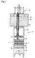
- the fuel assembly 10 basically comprises a lower end structure or bottom nozzle 16 for supporting the assembly on the lower core plate (not shown) in the core region of a reactor (not shown); a number of guide tubes or thimbles 18 longitudinally projecting upward from the bottom nozzle 16; a plurality of transverse grids 20 axially spaced along the guide thimbles 18; and organized array of elongate fuel rods 22 transversely spaced and supported by the grids 20; and instrumentation tube 24 located in the center of the assembly; and an upper end structure or top nozzle 26 attached to the upper ends of the guide thimbles 18 to form therewith an integral assembly capable of being conventionally handled without damaging the assembly components.
- the fuel assembly 10 does not form part of the invention proper and, therefore, will not be described herein in further detail.
- the upper core support plate 12 being conventional, extends across the top of the fuel assembly 10 as well as across the top of the other fuel assemblies (not shown) within the core.
- the core plate 12 has a multiplicity of coolant flow passages 28 (only one of which is seen in Figure 1) which allow coolant to pass upwardly through the core. At least some of these passages or openings are axially aligned with guide thimbles 18 so as to enable control rods 30 to be inserted through the core plate passages and into the guide thimbles 18 of fuel assembly 10.
- the spider assembly 14 Connected to the upper ends of the control rods 30 is the spider assembly 14 which supports the control rods for vertical movement thereof within the guide thimbles 18 by means of a conventional drive mechanism (not shown). It should be noted that although the spider assembly is shown in Figure 1 as disposed above the core plate 12, upon which it will seat when the control rods 30 are fully inserted in the guide thimbles 18, there are other arrangements with which the spider assembly 14 could be utilized and in which it would be located between the bottom of the core plate and the top of the fuel assembly.
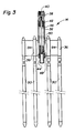
- the spider assembly 14 comprises a central hub 32, a plurality of vanes 34 radially extending outwardly from the hub 32, and a plurality of fingers 36 on the vanes 34 for connection with the upper ends of the control rods 30.
- the central hub 32 is preferably in the form of an elongate cylindrical tube having a solid upper neck portion 38 formed integral therewith and including an internally threaded segment 40 for connection to the drive mechanism (not shown) of the reactor which is employed to raise and lower the assembly together with the control rods when in use, as well known in the art.
- the tubular hub 32 houses a load absorbing mechanism in the form of a coil spring 42 which is held partially compressed between a nipple 44, slidably supported in the lower end of the tube, and the inner face of neck portion 38.
- a bolt 46 extends through an opening in the end wall of the nipple 44 and axially through the coil spring 42, and it is threadably engaged with the neck portion 38, the arrangement being such that the compression and hence force of the spring 42 can be adjusted by turning the bolt 46.
- the lower end of the nipple 44 is adapted to seat in a shallow cavity (not shown) in the top surface of the core plate 12 so as to assist in proper alignment of the control rods 30 with the core plate openings 28 of the core plate and with the guide thimbles 18.
- the primary purpose of such absorbing mechanism is to prevent shock loading of the core plate and the fuel assembly as the spider assembly 14 engages the top of the core plate 12 upon full insertion of the control rods into the guide thimbles.
- the tubular hub 32 has a plurality of circumferentially spaced vertical slots 48 extending through the wall thereof, which slots 48 preferably are all at the same axial or height location on the tube.
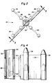
- each vane 34 there are four vanes 34 each having two fingers 36 associated therewith.
- the vanes 34 are in the form of linear bars whereas the fingers 36 have the form of elongate cylinders with dome-shaped upper ends.
- the diameter of each finger 36 is greater than the transverse thickness of the vane portion extending between any two fingers on a given vane-finger sub-unit.
- each vane 34 together with its two associated fingers 36 is formed as a sub-unit of one-piece construction. The preferred method of manufacturing such a vane-finger sub-unit is by machining, in accordance with well-known techniques, a bar stock to conform to the desired configuration as shown.
- each vane-finger sub-unit has an integral extension 50 (Fig. 4) of dimensions such as to be fit tightly into one of the slots 48 of the hub 32, thereby to properly position the vane-finger sub-unit on the hub to which it can then be rigidly joined in a suitable manner, such as by brazing or the like. Due to the slots, a suitable weld can be easily obtained because they allow gases generated for the brazing operation to escape to the atmosphere. Either after or before (normally before) the vane-finger sub-units are brazed to the hub 32, the lower end portion of each finger 36 is drilled and internally threaded for connection to the upper end of a control rod. From the above, it will be appreciated that fabricating the spider assembly 14 requires only a few steps, and substantially fewer than are involved in making conventional spider assemblies.
- the vanes 34 are angularly spaced about the circumference of the central hub 32 approximately ninety degrees apart so that vertical planes extending through the vanes which are diametrically opposed to each other are in orthogonal relationship one to the other.
- the two fingers 36 associated with each vane 34 are spaced apart, one finger (the outer finger) being located at the outer distal end of the vane, and the other or inner finger being located between the outer finger and the hub 32.
- the relationship of the outer and inner fingers 36 with respect to the hub 32 is such that their vertical axes are parallel to one another as well as to the vertical axis of the hub 32, and that the vertical axes of the inner and outer fingers associated with any one vane lie in the same plane as the vertical axis of the hub.
- the configuration and relationship of the vanes 34 are such that the portion of each vane extending between the hub 32 and the inner finger (first or inner vane portion), and the portion of the vane extending between the inner finger and the outer finger (second or outer vane portion) lie in the same vertical plane and are each rectangular as viewed in elevation.
- the upper edge and the lower edge of the first vane portion are collinear with the respective upper and lower edges of the second vane portion. Moreover, these respective upper and lower collinear edges are parallel to one another.
- the rectangular vane portion on any given vane rigidly interconnects the associated fingers and maintains them in proper relationship with respect to one another as well as to the central hub, thus preventing deformation of the spider assembly 14 when subjected to large moment forces such as experienced during stepping action.
- the axial height of the inner finger above the upper edge of the vane is greater than the axial height of the outer finger above the upper edge of the vane. This axial extension of the inner fingers beyond the outer fingers facilitates the proper alignment of the spider assembly with the upper internals of the reactor.
Landscapes
- Physics & Mathematics (AREA)
- Engineering & Computer Science (AREA)
- Chemical & Material Sciences (AREA)
- Chemical Kinetics & Catalysis (AREA)
- Plasma & Fusion (AREA)
- General Engineering & Computer Science (AREA)
- High Energy & Nuclear Physics (AREA)
- Fuel-Injection Apparatus (AREA)
- Monitoring And Testing Of Nuclear Reactors (AREA)
- Turbine Rotor Nozzle Sealing (AREA)
- Molds, Cores, And Manufacturing Methods Thereof (AREA)
Applications Claiming Priority (2)
| Application Number | Priority Date | Filing Date | Title |
|---|---|---|---|
| US59516384A | 1984-03-30 | 1984-03-30 | |
| US595163 | 1984-03-30 |
Publications (2)
| Publication Number | Publication Date |
|---|---|
| EP0159509A1 true EP0159509A1 (de) | 1985-10-30 |
| EP0159509B1 EP0159509B1 (de) | 1989-01-04 |
Family
ID=24382015
Family Applications (1)
| Application Number | Title | Priority Date | Filing Date |
|---|---|---|---|
| EP85102689A Expired EP0159509B1 (de) | 1984-03-30 | 1985-03-09 | Steuerstabjoch für eine Kernbrennstoffkassette |
Country Status (5)
| Country | Link |
|---|---|
| EP (1) | EP0159509B1 (de) |
| JP (1) | JPS60225090A (de) |
| KR (1) | KR920007742B1 (de) |
| DE (1) | DE3567306D1 (de) |
| ES (1) | ES296662Y (de) |
Cited By (8)
| Publication number | Priority date | Publication date | Assignee | Title |
|---|---|---|---|---|
| EP0225805A1 (de) * | 1985-12-09 | 1987-06-16 | Westinghouse Electric Corporation | Steuerstabjoch mit Flügeln |
| FR2602903A1 (fr) * | 1986-08-13 | 1988-02-19 | Framatome Sa | Barre absorbante a dispositif d'amortissement integre |
| FR2608306A1 (fr) * | 1986-12-10 | 1988-06-17 | Framatome Sa | Dispositif d'amortissement de chute de barres absorbantes pour assemblage de combustible nucleaire |
| US4855100A (en) * | 1988-03-02 | 1989-08-08 | Westinghouse Electric Corp. | Reconstitutable control rod spider assembly |
| FR2633435A1 (fr) * | 1988-06-28 | 1989-12-29 | Framatome Sa | Grappe de reglage a crayons demontables pour assemblage combustible nucleaire |
| US4993864A (en) * | 1988-12-15 | 1991-02-19 | Westinghouse Electric Corp. | Reconstitutable control assembly having removable control rods with detachable split upper end plugs |
| FR2661771A1 (fr) * | 1990-05-07 | 1991-11-08 | Framatome Sa | Equipements internes de reacteur nucleaire a guides de grappe. |
| FR2742912A1 (fr) * | 1995-12-26 | 1997-06-27 | Framatome Sa | Grappe de commande pour reacteur nucleaire, a crayons demontables |
Families Citing this family (1)
| Publication number | Priority date | Publication date | Assignee | Title |
|---|---|---|---|---|
| JPS63180594A (ja) * | 1987-01-20 | 1988-07-25 | Ishikawajima Harima Heavy Ind Co Ltd | 舵成型方法 |
Citations (5)
| Publication number | Priority date | Publication date | Assignee | Title |
|---|---|---|---|---|
| FR1560777A (de) * | 1967-04-14 | 1969-03-21 | ||
| DE2406595A1 (de) * | 1973-02-20 | 1974-08-29 | Combustion Eng | Kernreaktor mit pufferung der steuerstaebe |
| US4326919A (en) * | 1977-09-01 | 1982-04-27 | Westinghouse Electric Corp. | Nuclear core arrangement |
| EP0054787A2 (de) * | 1980-12-16 | 1982-06-30 | Westinghouse Electric Corporation | Mit Spektralverschiebung gesteuerter Kernreaktor |
| EP0079828A1 (de) * | 1981-11-13 | 1983-05-25 | Framatome | Führungseinrichtung für ein Kontrollbündel eines Kernreaktors |
Family Cites Families (1)
| Publication number | Priority date | Publication date | Assignee | Title |
|---|---|---|---|---|
| CA1132728A (en) * | 1978-10-18 | 1982-09-28 | Lewis A. Walton | Control component structure |
-
1985
- 1985-03-09 EP EP85102689A patent/EP0159509B1/de not_active Expired
- 1985-03-09 DE DE8585102689T patent/DE3567306D1/de not_active Expired
- 1985-03-26 ES ES1985296662U patent/ES296662Y/es not_active Expired
- 1985-03-29 JP JP60064088A patent/JPS60225090A/ja active Pending
- 1985-03-30 KR KR1019850002163A patent/KR920007742B1/ko not_active Expired
Patent Citations (5)
| Publication number | Priority date | Publication date | Assignee | Title |
|---|---|---|---|---|
| FR1560777A (de) * | 1967-04-14 | 1969-03-21 | ||
| DE2406595A1 (de) * | 1973-02-20 | 1974-08-29 | Combustion Eng | Kernreaktor mit pufferung der steuerstaebe |
| US4326919A (en) * | 1977-09-01 | 1982-04-27 | Westinghouse Electric Corp. | Nuclear core arrangement |
| EP0054787A2 (de) * | 1980-12-16 | 1982-06-30 | Westinghouse Electric Corporation | Mit Spektralverschiebung gesteuerter Kernreaktor |
| EP0079828A1 (de) * | 1981-11-13 | 1983-05-25 | Framatome | Führungseinrichtung für ein Kontrollbündel eines Kernreaktors |
Cited By (17)
| Publication number | Priority date | Publication date | Assignee | Title |
|---|---|---|---|---|
| EP0225805A1 (de) * | 1985-12-09 | 1987-06-16 | Westinghouse Electric Corporation | Steuerstabjoch mit Flügeln |
| US4826648A (en) * | 1986-08-13 | 1989-05-02 | Framatome | Neutron absorbing bar damping device |
| FR2602903A1 (fr) * | 1986-08-13 | 1988-02-19 | Framatome Sa | Barre absorbante a dispositif d'amortissement integre |
| EP0256934A1 (de) * | 1986-08-13 | 1988-02-24 | Framatome | Absorberstab mit integrierter Stossdämpfungseinrichtung |
| US5076995A (en) * | 1986-12-10 | 1991-12-31 | Framatome | Shock damping device for neutron absorbing bars |
| EP0274311A1 (de) * | 1986-12-10 | 1988-07-13 | Framatome | Aufpralldämpfer für Absorbierstäbe bei Kernbrennelementen |
| FR2608306A1 (fr) * | 1986-12-10 | 1988-06-17 | Framatome Sa | Dispositif d'amortissement de chute de barres absorbantes pour assemblage de combustible nucleaire |
| US4855100A (en) * | 1988-03-02 | 1989-08-08 | Westinghouse Electric Corp. | Reconstitutable control rod spider assembly |
| FR2633435A1 (fr) * | 1988-06-28 | 1989-12-29 | Framatome Sa | Grappe de reglage a crayons demontables pour assemblage combustible nucleaire |
| EP0349379A1 (de) * | 1988-06-28 | 1990-01-03 | Framatome | Regelspinne mit demortierbaren Stäben für ein Kernbrennstabbündel |
| US5183626A (en) * | 1988-06-28 | 1993-02-02 | Framatome | Control cluster including demountable fuel for a nuclear fuel assembly |
| US4993864A (en) * | 1988-12-15 | 1991-02-19 | Westinghouse Electric Corp. | Reconstitutable control assembly having removable control rods with detachable split upper end plugs |
| FR2661771A1 (fr) * | 1990-05-07 | 1991-11-08 | Framatome Sa | Equipements internes de reacteur nucleaire a guides de grappe. |
| EP0456562A1 (de) * | 1990-05-07 | 1991-11-13 | Framatome | Innere Anlage eines Stabbündelführungskernreaktors |
| FR2742912A1 (fr) * | 1995-12-26 | 1997-06-27 | Framatome Sa | Grappe de commande pour reacteur nucleaire, a crayons demontables |
| EP0782150A1 (de) * | 1995-12-26 | 1997-07-02 | Framatome | Mit abnehmbaren Stäben versehenes Kernreaktorsteuerstabbündel |
| US5889832A (en) * | 1995-12-26 | 1999-03-30 | Framatome | Nuclear reactor control cluster having removable rods |
Also Published As
| Publication number | Publication date |
|---|---|
| JPS60225090A (ja) | 1985-11-09 |
| EP0159509B1 (de) | 1989-01-04 |
| DE3567306D1 (en) | 1989-02-09 |
| ES296662Y (es) | 1988-05-16 |
| ES296662U (es) | 1987-12-16 |
| KR920007742B1 (ko) | 1992-09-16 |
| KR850006767A (ko) | 1985-10-16 |
Similar Documents
| Publication | Publication Date | Title |
|---|---|---|
| US5068083A (en) | Dashpot construction for a nuclear reactor rod guide thimble | |
| EP0589312B1 (de) | Fussstück für Kernbrennstabbündel | |
| US3992259A (en) | Fuel assembly for a nuclear reactor | |
| EP0243917B1 (de) | Kernbrennstabbündel | |
| EP0159509B1 (de) | Steuerstabjoch für eine Kernbrennstoffkassette | |
| EP0138606A2 (de) | Kernreaktorbrennelement mit Kopfteil und Retentionssystem | |
| EP0140588B1 (de) | Kernreaktorbrennstoffzusammenbau mit abnehmbarer oberer Düse | |
| US4820475A (en) | Burnable absorber rod push out attachment joint | |
| JPH0214673B2 (de) | ||
| US8582714B2 (en) | Fixed cluster having a spider-like support, corresponding pressurized water nuclear reactor core and assembly comprising a nuclear fuel assembly and such a fixed cluster | |
| US4684498A (en) | Guide thimble captured locking tube in a reconstitutable fuel assembly | |
| EP0158812A1 (de) | Steuerstabjoch für eine Kernbrennstoffkassette | |
| US4716018A (en) | End plug with truncated tapered leading end configuration | |
| US4873051A (en) | Nuclear fuel grid outer strap | |
| KR101640942B1 (ko) | 원자로용 핵연료 집합체 | |
| US6654438B1 (en) | Control rod for boiling water reactor, unit for control rod and production method of control rod | |
| US4699760A (en) | Fuel assembly skeleton with structural and non-structural top nozzle/guide thimble joints | |
| US5473649A (en) | Fuel element for a light-water nuclear reactor | |
| US6389094B1 (en) | Integral forged shroud flange for a boiling water reactor | |
| JPH0631751B2 (ja) | 燃料集合体を再構成可能にする方法及びその上部ノズルの取付構造 | |
| US3945886A (en) | Control rod for nuclear reactor | |
| JP3468943B2 (ja) | 沸騰水型原子炉用制御棒 | |
| EP0186012B1 (de) | Entlüfteter oberer Halter zur Erleichterung beim Austausch eines Kopfstückes an einem wiederzusammengebauten Kernbrennelementbündel | |
| US7149273B2 (en) | Method of fabricating a nuclear reactor fuel assembly grid | |
| EP0158791B1 (de) | Steuerstabbaugruppe für Kernbrennelemente |
Legal Events
| Date | Code | Title | Description |
|---|---|---|---|
| PUAI | Public reference made under article 153(3) epc to a published international application that has entered the european phase |
Free format text: ORIGINAL CODE: 0009012 |
|
| AK | Designated contracting states |
Designated state(s): BE DE FR GB IT SE |
|
| 17P | Request for examination filed |
Effective date: 19860313 |
|
| 17Q | First examination report despatched |
Effective date: 19870430 |
|
| ITF | It: translation for a ep patent filed | ||
| GRAA | (expected) grant |
Free format text: ORIGINAL CODE: 0009210 |
|
| AK | Designated contracting states |
Kind code of ref document: B1 Designated state(s): BE DE FR GB IT SE |
|
| REF | Corresponds to: |
Ref document number: 3567306 Country of ref document: DE Date of ref document: 19890209 |
|
| ET | Fr: translation filed | ||
| ITTA | It: last paid annual fee | ||
| PLBE | No opposition filed within time limit |
Free format text: ORIGINAL CODE: 0009261 |
|
| STAA | Information on the status of an ep patent application or granted ep patent |
Free format text: STATUS: NO OPPOSITION FILED WITHIN TIME LIMIT |
|
| 26N | No opposition filed | ||
| PGFP | Annual fee paid to national office [announced via postgrant information from national office to epo] |
Ref country code: FR Payment date: 19901218 Year of fee payment: 7 |
|
| PGFP | Annual fee paid to national office [announced via postgrant information from national office to epo] |
Ref country code: GB Payment date: 19901220 Year of fee payment: 7 |
|
| PGFP | Annual fee paid to national office [announced via postgrant information from national office to epo] |
Ref country code: SE Payment date: 19901227 Year of fee payment: 7 |
|
| PGFP | Annual fee paid to national office [announced via postgrant information from national office to epo] |
Ref country code: BE Payment date: 19910114 Year of fee payment: 7 |
|
| PGFP | Annual fee paid to national office [announced via postgrant information from national office to epo] |
Ref country code: DE Payment date: 19910330 Year of fee payment: 7 |
|
| PG25 | Lapsed in a contracting state [announced via postgrant information from national office to epo] |
Ref country code: GB Effective date: 19920309 |
|
| PG25 | Lapsed in a contracting state [announced via postgrant information from national office to epo] |
Ref country code: SE Effective date: 19920310 |
|
| PG25 | Lapsed in a contracting state [announced via postgrant information from national office to epo] |
Ref country code: BE Effective date: 19920331 |
|
| BERE | Be: lapsed |
Owner name: WESTINGHOUSE ELECTRIC CORP. Effective date: 19920331 |
|
| GBPC | Gb: european patent ceased through non-payment of renewal fee | ||
| PG25 | Lapsed in a contracting state [announced via postgrant information from national office to epo] |
Ref country code: FR Effective date: 19921130 |
|
| PG25 | Lapsed in a contracting state [announced via postgrant information from national office to epo] |
Ref country code: DE Effective date: 19921201 |
|
| REG | Reference to a national code |
Ref country code: FR Ref legal event code: ST |
|
| EUG | Se: european patent has lapsed |
Ref document number: 85102689.8 Effective date: 19921005 |