EP0159525A2 - Messgerät für Getränkeleitungen - Google Patents
Messgerät für Getränkeleitungen Download PDFInfo
- Publication number
- EP0159525A2 EP0159525A2 EP85103050A EP85103050A EP0159525A2 EP 0159525 A2 EP0159525 A2 EP 0159525A2 EP 85103050 A EP85103050 A EP 85103050A EP 85103050 A EP85103050 A EP 85103050A EP 0159525 A2 EP0159525 A2 EP 0159525A2
- Authority
- EP
- European Patent Office
- Prior art keywords
- measuring
- measuring device
- housing
- connecting parts
- lines
- Prior art date
- Legal status (The legal status is an assumption and is not a legal conclusion. Google has not performed a legal analysis and makes no representation as to the accuracy of the status listed.)
- Granted
Links
Images
Classifications
-
- G—PHYSICS
- G01—MEASURING; TESTING
- G01F—MEASURING VOLUME, VOLUME FLOW, MASS FLOW OR LIQUID LEVEL; METERING BY VOLUME
- G01F15/00—Details of, or accessories for, apparatus of groups G01F1/00 - G01F13/00 insofar as such details or appliances are not adapted to particular types of such apparatus
- G01F15/18—Supports or connecting means for meters
- G01F15/185—Connecting means, e.g. bypass conduits
-
- B—PERFORMING OPERATIONS; TRANSPORTING
- B08—CLEANING
- B08B—CLEANING IN GENERAL; PREVENTION OF FOULING IN GENERAL
- B08B9/00—Cleaning hollow articles by methods or apparatus specially adapted thereto
- B08B9/02—Cleaning pipes or tubes or systems of pipes or tubes
- B08B9/027—Cleaning the internal surfaces; Removal of blockages
- B08B9/04—Cleaning the internal surfaces; Removal of blockages using cleaning devices introduced into and moved along the pipes
- B08B9/053—Cleaning the internal surfaces; Removal of blockages using cleaning devices introduced into and moved along the pipes moved along the pipes by a fluid, e.g. by fluid pressure or by suction
- B08B9/055—Cleaning the internal surfaces; Removal of blockages using cleaning devices introduced into and moved along the pipes moved along the pipes by a fluid, e.g. by fluid pressure or by suction the cleaning devices conforming to, or being conformable to, substantially the same cross-section of the pipes, e.g. pigs or moles
-
- B—PERFORMING OPERATIONS; TRANSPORTING
- B67—OPENING, CLOSING OR CLEANING BOTTLES, JARS OR SIMILAR CONTAINERS; LIQUID HANDLING
- B67D—DISPENSING, DELIVERING OR TRANSFERRING LIQUIDS, NOT OTHERWISE PROVIDED FOR
- B67D1/00—Apparatus or devices for dispensing beverages on draught
- B67D1/08—Details
- B67D1/0855—Details concerning the used flowmeter
-
- G—PHYSICS
- G01—MEASURING; TESTING
- G01F—MEASURING VOLUME, VOLUME FLOW, MASS FLOW OR LIQUID LEVEL; METERING BY VOLUME
- G01F1/00—Measuring the volume flow or mass flow of fluid or fluent solid material wherein the fluid passes through a meter in a continuous flow
- G01F1/05—Measuring the volume flow or mass flow of fluid or fluent solid material wherein the fluid passes through a meter in a continuous flow by using mechanical effects
- G01F1/06—Measuring the volume flow or mass flow of fluid or fluent solid material wherein the fluid passes through a meter in a continuous flow by using mechanical effects using rotating vanes with tangential admission
-
- G—PHYSICS
- G01—MEASURING; TESTING
- G01F—MEASURING VOLUME, VOLUME FLOW, MASS FLOW OR LIQUID LEVEL; METERING BY VOLUME
- G01F15/00—Details of, or accessories for, apparatus of groups G01F1/00 - G01F13/00 insofar as such details or appliances are not adapted to particular types of such apparatus
-
- G—PHYSICS
- G01—MEASURING; TESTING
- G01F—MEASURING VOLUME, VOLUME FLOW, MASS FLOW OR LIQUID LEVEL; METERING BY VOLUME
- G01F15/00—Details of, or accessories for, apparatus of groups G01F1/00 - G01F13/00 insofar as such details or appliances are not adapted to particular types of such apparatus
- G01F15/14—Casings, e.g. of special material
Definitions
- the invention relates to a measuring device for building in lines for beverages, in particular for beer, with a measuring housing and connecting ends for lines.
- Such lines for wine, mineral water and also beer must be cleaned at regular intervals as well as measuring instruments used in them, for example flow meters or the like. With a number of drinks this is no problem, here a cleaning fluid can be pressed through the line and the measuring devices, which cleans the line and measuring devices. It is therefore unnecessary to bend the measuring device with lines for such drinks.
- the invention has for its object to provide a measuring device, bel the aforementioned Nachelle can be avoided by easy removal and installation.
- the above-mentioned object is achieved in a measuring device for beverage lines with a measuring housing and connecting ends in that the connecting ends are designed as intermediate pieces which can be firmly connected to the line ends and the intermediate pieces are releasably connected to the measuring housing via connecting parts. Due to the configuration according to the invention, the measuring housing can be removed from the line system or reinstalled in a few seconds.
- An extremely preferred embodiment provides that connecting points of the intermediate pieces which are connected to the connecting parts of the measuring housing are designed to be complementary to one another.
- the two line ends can be connected to one another for cleaning just as quickly after removal of the measuring housing, without cross-sectional reductions, as through the measuring housing itself, hindering the cleaning with foam balls.
- the connecting parts are connected to one another via plug-in couplings or that the connecting parts have bayonet-type closures.
- An extremely preferred embodiment provides that the connecting parts of the measuring housing are screwed to it, so that once the measuring housing has been removed, it can also be opened in a simple and convenient manner and thus cleaned itself, the assembly being simplified and accelerated in that the measuring housing an upper and a lower part and the upper and lower parts are connected by a bayonet lock.
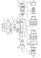
- the measuring device has a measuring housing consisting of an upper part 1 and a lower part 2, in which a measuring vane is rotatably mounted, which is set in rotation by the liquid flowing through the lower part 2 of the measuring housing and thus effects the measurement via a measuring electronics .
- the measuring wing 3 is only loosely inserted with a diamond bearing on tip (not shown in detail) in the lower part 2 of the measuring housing and is held by the attached upper part 1.
- the upper part 1 has bevels 1 'provided with bevels 1', by means of which the measuring wing 3 is brought into position when the upper plate 1 is put on and the bearing tip 3 'is guided into the upper diamond bearing (not shown)
- Closing has the lower part in its edge region in the axial direction protruding hooks 2 ', which also have bevels 2 ".
- the upper part 1 is guided with a hollowed ring-shaped extension 1.1 over the hooks 2", centered by the bevels 2 "and centered by a Rotation by a small angle securely fixed by the hooks 2 'in accordance with the associated fixation element, the upper and lower parts 1, 2 have a ring seal (not shown) with which the interior of the housing is sealed.
- the lower part 2 of the measuring housing has an inlet opening 2.1 and an outlet opening 2.2 in alignment with the lower part 2 perpendicular to the direction in which the upper tella 1 is placed.
- a transition piece 4 is screwed into the pouring opening with a nozzle bobbin 4 ', the nozzle nipple 4' being attached in front of the repetfiögel 3.
- a coupling part 6 is placed by means of a plug-in coupling, which in its opposite end by means of a piece of hose 9 to be inserted into a hose in a press fit and a piece of the hose by screwing to the coupling point 6 firmly against the coupling part 6 pushing union nuts is firmly connected to the hose or the line.By means of the plug-in coupling connection between transfer piece 4 and coupling part 6, these two points can be released quickly and comfortably.
- a further transition piece 5 is screwed into the outlet end 2.2 of the lower housing part 2, by means of which a further coupling part 6 'identical to the coupling position 6 is also omitted.
- the coupling part 6 is also connected via a plug-in coupling with a quick and easy detachable connection to a connector 8, by means of a toggle nut 7 on a tap battery or corresponding Connection pieces of a tap battery can be attached.
- the plug-in couplings of parts 4, 6, 6 'and 8 are known per se.
- the parts 6, 6 'have balls under spring pressure which are drawn into the cross-sectionally conical grooves 4.1 and 8.1 of the parts 4, 8 and locked in these grooves.
- the O-rings 11 are arranged on the outer circumference of the parts 4, 8 and not in the interior of the coupling part 6, 6 'so that they can be easily removed and cleaned.
- the measuring housing is removed from the line and the coupling part 6, which is connected to the hose via parts 9, 10, is plugged directly onto connector 8. Because the line can be cleaned mechanically directly by pressing foam balls through it.
- the interior of the measuring housing 1, 2 itself is disassembled in the manner described above, cleaned separately and then assembled as described above.
- the first coupling part 6 is detached from the connector 8 and the measuring housing is reinserted into the line by placing the coupling part 6 connected to the hose on the transition piece 4 and the coupling part 6 'located on the measuring housing 1, 2 again is plugged onto the connector.
Landscapes
- Physics & Mathematics (AREA)
- Fluid Mechanics (AREA)
- General Physics & Mathematics (AREA)
- Engineering & Computer Science (AREA)
- Mechanical Engineering (AREA)
- Measuring Volume Flow (AREA)
- Measuring Fluid Pressure (AREA)
- Weight Measurement For Supplying Or Discharging Of Specified Amounts Of Material (AREA)
- Loading And Unloading Of Fuel Tanks Or Ships (AREA)
- Level Indicators Using A Float (AREA)
- Devices For Dispensing Beverages (AREA)
- Beverage Vending Machines With Cups, And Gas Or Electricity Vending Machines (AREA)
Abstract
Description
- Dle Erfindung betrifft ein Meßgerät zum Elnbau In Leitungen für Getränke, Insbesondere für Bier, mit einem Meßgehäues sowle Anschlußenden für Leitungen.
- Derartige Leitungen für Wein, Mineralwasser und auch Bier müssen In regelmäßigen Abständen ebenso wie In ihnen eingesetzte Meßgeräte, belspielsweise Durchflußmesser od. ddl., gereingigt werden. Bei einer Reihe von Getränken Ist dies problemlos, hier kann durch die Leitung und die Meßgeräte eine Reinigungeflussigkeit gedrückt werden, die Leitung und Meßgeräte reinigt. Ein Ausbeuen des Meßgerätes erübrigt sich daher bei Leitungen für solche Getränke.
- Bei anderen Getränken, insbesondere bei Bier treten Ablagerungen, wie Bierhefeabiagerungen, aufr, die nur mechanisch entfernt werden können. Zu diesem Zwecke müssen kleine Schaumstoffküpelchen durch die Leitungen gepreßt werden. Derartige Kügelchen können abe r nicht durch das Meßgerät gepreßt werden, eondem würden In diesem vielmehr blockiert. Es Ist daher erforderlich, das Meßgerät suszubauen. Der Arsbau des Meßgeräte wer bisher umständlich und sufwendig.
- Der Erfindung liegt die Aufgabe zugrunde, ein Meßgerät zu schaffen, bel dem die vorgenennten Nachtelle durch leichte Aus- und Einbaubarkeit vermieden werden.
- Neuerungsgemäß wird die genannte Aufgabe bei einem Meßgerät für Getränkeleitungen mit einem Meßgehäuse sowle Anschlußenden dadurch gelöst, daß die Anschlußenden als mit den Leitungsenden fest verbindbare Zwischenstücke ausgebildet sind und die Zwlschenstücke über Verbindunpsteile mit dem Meßgehäuse lösbar verbunden sind. Durch die erfindungsgemaße Ausgestaltung kann das Meßgehäuse In wenigen Sekunden aus dem Leitungasystem ausgebaut bzw. wieder eingebaut worden. Durch eine äußerst bevorzugte Ausgestaltung Ist vorgesehen, daß mit den Verbindungsteilen des Meßgehäuses In Verbindung stehende Verbindunpstelle der Zwischenetücke zueinander komplementär ausgebildet sind. Hierbei können dem ebenso schnell die beiden Leitungsenden nach Ausbau des Meßgehäuses schnell zur Reinigung miteinander verbunden werden, ohne daß Querschnittsver- minderungen, wie durch das Meßgehäuse selbst, die Reinigung mit Schaumstoffkugeln behindem. Gernäß weiterer Ausgestaltung ist vorgesehen, daß die Verbindungsteile über Steckkupplungen miteinander verbunden sind oder daß die Verbindunpsteile bajonettartige Verschlüsse aufweisen.
- Eine äußerst bevorzugte Ausgestaltung sieht vor, daß die Verbindungsteile des Meßgehäuses mit diesem verschraubt sind, hierdurch kann nach erfolgtem Ausbau des Meßgshäuses dieses ebenfalls In einfacher und bequemer Welse geöffnet und damit selbst gereinigt werden, wobei das Zusammenfügen dadurch vereinfacht und beschleunigt wird, daß das Meßghäuse ein Ober- und ein Unterteil sufweist und das Qber- und Unterteil durch einen Bajonettverschluß miteinander verbunden sind.
- Weitere Vorteile und Merkmale der Neuerung ergeben sich sus den An- spüchen und sus der nachfolgenden Heschrelbung, In der ein Ausführungs- beispiel das erfindungegernäßen Meßgeräte unter Bezugnshme auf die Zeichnung Im einzelnen erläutert ist. Dabel zeigt die einzige Figur:
- Die bevorzugte Ausführungsform des erfindungsgemäßen Gerätes In auselnandergezogener Derstellung der Einzelteile.
- Das erfindungsgemäße Meßgerät weist ein aus einem Oberteil 1 und einem Unterteil 2 bestehendes Meßgehäuse auf, In dem ein Meßflügel drehbar gelagert Ist, der durch die durch das Unterteil 2 des Meßgehäuses fließende Flüssigkeit In Drehung versetzt wird und derart über eine Meß- elektronk die Messung bewirkt. Der Meßflügel 3 Ist lediglich mit einem Diamantiager auf Spitze (im einzelnen nicht dargestellt) in das Unterteil 2 des Meßgehäuses locker eingesetzt und wird durch das aufgesetzte Oberteil 1 gehalten. Zur Zentrierung weist daa Oberteil 1 mit Anschrä- gungen 1" versehene Staurippen 1' auf, durch die der Meßflügel 3 beim Aufsetzen des Obertells 1 In Position gebracht und die Lagerspitze 3' ins obere Diamantlager (nicht dargestellt) geführt wird. Zum sicheren Verschließen weist das Unterteil In seinem Randbereich in axialer Richtung hervostehande Haken 2' auf, die ebenfalls Abschrägungen 2" aufwesen. Das Oberteil 1 wird mit einem aulgehölten ringförmigen Ansatz 1.1 über die Haken 2" geführt, dabel durch die Schrägen 2" zentriert und durch eine Drehung um einen geringen Winkel von den Haken 2' entsprechend susgestaiteter und zugeordneter Fixierslemante sicher festgelegt. Ober-und Unterteil 1, 2 weisen eine (nicht dergestellte) Ringdichtung auf, mit der der innenraum des Gehäuses abgedichtet wird.
- Der Unterteil 2 des Meßgehäuses weist senkrecht zur Aufsetzrichtung des Obertella 1 auf den Unterteil 2 miteinander fluchtend eine Einlaßöffnung 2.1 und eine Auslaßöffnung 2.2 auf. In die Einisßöffnung Ist ein Über- gangestück 4 mit einem Düsennlppel 4' eingeschraubt, wobei der Düsennippel 4' vor dem Maßfiögel 3 angeondnet Ist. Auf dem Im Düsennippel 4 gepenüberliegenden Ende 4" des Übergangsstücks 5 Ist mittels Steckupplung ein Kupplunpsteil 6 lösber aufgesetzt, das in seinem gegenüberliegenden Ende mittels eines In einem Schlauch Im Preßsitz einzusetzenden Schlauchstücks 9 und einer das Schlauchstück durch Verschraubung mit dem Kupplungstell 6 fest gegen das Kupplungsteil 6 drückende Überwurfmutten mit dem Schlauch oder der Leitung fest verbunden ist. Durch die Steckkupplungsverbindung zwischen Überganpsstück 4 und Kupplungsteil 6 können diese beiden Telle schnell und bequem gelöst worden.
- In das Auslaßende 2.2 des Gehäuseunterteils 2 ist in entsprechender Weise ein weiteres Übergangsstück 5 eingeschraubt, mit dem weiterhin ein dem Kupplungstell 6 identisches weiteres Kupplungsteil 6' vertunden ist. Das Kuppfunsteil 6 Ist ebenfalls über eine Steckkuppiun mit schnell und einfach lösbar mit einem Anschlußstück 8 verbunden, mittels einer Knebelmutter 7 an einer Schankbatterie bzw. entsprechenden Verbindungsstüeken einer Schankbatterie befestigbar ist. Die Steckkupplungen der Teile 4, 6, 6' und 8 sind an sich bekannt. Die Teile 6, 6' weisen unter Federdruck stehende Kugeln auf, die in den im Querschnitt konischen Nuten 4.1 bzw. 8.1 der Teile 4, 8 hineingezogen und in diesen Nuten arretiert werden Durch die konische Auspestaitung werden die Kupplunpen 6, 6' gegen dichtend auf den Teilen 4, 8 einsitzenden O-R ingen 11 gedrückt, so dafeine zuverlässige Abdichtung erfolgt. Die O-Ringe 11 sind am Außenumfang der Teile 4, 8 und nicht Im inneren der Kupplunpsteils 6, 6' angsordnet, damit sie leicht entfemt und gereinigt werden können.
- Sollten die Leitungen gereiningt werden, so werden die Stockkupplungen der Teile 4, 6, 6', 6 gelöst, das Meßgehäuse sus der Leitung hersusgenommen und des über die Teile 9, 10 mit dem Schlauch werbundene Kupplungsteil 6 direkt auf das Anschlußstück 8 aufgesteckt. Denn kann die Leitung direkt mechnisch durch Hindurchpreßen von Schaumstoffkugein gereinigt werden. Des Innere des Meßgehäuses 1, 2 selbst wird In der oben beschriebenen Weise auseinandergenommen, separat gereinigt und anschließend zusammengesetzt, wie oben beschrieben. Nach Reinigen der Leitung wird das erste Kupplungsteil 6 wieder vom Anschlußstück 8 gelöst und das Meßgehäuse wieder in die Leitung eingesetzt, In dem das mit dem Schlauch verbundene Kupplungsteil 6 auf das Übergangsstück 4 aufgesetzt wird und das am Meßgehäuse 1, 2 befindliche Kupplungsteil 6' wieder auf das Anschlußstück aufgesteckt wird.
- Die in der vorstehenden Beschreibung, in der Zeichnung sowie in den Ansprüchen offenbarten Merkmale der Erfindung können sowohl einzeln als auch in geeigneten Kombinationen für die Verwirkichung der Erfindung in ihren verschiedenen Ausführungsformen wesentlich sein.
Claims (7)
daß die Anschlußenden als mit den Leitungsenden fest vorbindbare Zwischenstücke (7, 8; 6, 9, 10) ausgebildet sind und die Zwischenstücke über Verbindungsteile (8, 6', 4, 6) mit dem Meßgehäise (1, 2) lösbar verbunden sind.
Priority Applications (1)
| Application Number | Priority Date | Filing Date | Title |
|---|---|---|---|
| AT85103050T ATE91114T1 (de) | 1984-03-20 | 1985-03-16 | Messgeraet fuer getraenkeleitungen. |
Applications Claiming Priority (2)
| Application Number | Priority Date | Filing Date | Title |
|---|---|---|---|
| DE19848408445U DE8408445U1 (de) | 1984-03-20 | 1984-03-20 | Messgeraet fuer getraenkeleitungen |
| DE8408445U | 1984-03-20 |
Publications (3)
| Publication Number | Publication Date |
|---|---|
| EP0159525A2 true EP0159525A2 (de) | 1985-10-30 |
| EP0159525A3 EP0159525A3 (en) | 1986-02-05 |
| EP0159525B1 EP0159525B1 (de) | 1993-06-30 |
Family
ID=6764922
Family Applications (1)
| Application Number | Title | Priority Date | Filing Date |
|---|---|---|---|
| EP85103050A Expired - Lifetime EP0159525B1 (de) | 1984-03-20 | 1985-03-16 | Messgerät für Getränkeleitungen |
Country Status (4)
| Country | Link |
|---|---|
| US (1) | US4666061A (de) |
| EP (1) | EP0159525B1 (de) |
| AT (1) | ATE91114T1 (de) |
| DE (3) | DE8408445U1 (de) |
Families Citing this family (27)
| Publication number | Priority date | Publication date | Assignee | Title |
|---|---|---|---|---|
| DE8408445U1 (de) * | 1984-03-20 | 1985-01-03 | Plüss, Heinz, Schöndühl | Messgeraet fuer getraenkeleitungen |
| CH673210A5 (de) * | 1987-07-17 | 1990-02-28 | Turmix Ag | |
| WO1993006439A1 (en) * | 1991-09-23 | 1993-04-01 | Futureflo System, Incorporated | Liquid flow meter |
| DE4412045A1 (de) * | 1994-04-08 | 1995-10-12 | Digmesa Ag | Meßgerät zum Einbau in Leitungen für Flüssigkeiten, insbesonders Wasser |
| EP0730138A1 (de) * | 1995-02-15 | 1996-09-04 | Kimmon Manufacturing Co., Ltd. | Wasserzähler |
| DE29614076U1 (de) * | 1996-08-15 | 1997-09-11 | Digmesa AG, Biel | Durchflußmeßgerät |
| US5876610A (en) * | 1997-03-19 | 1999-03-02 | Clack Corporation | Method and apparatus for monitoring liquid flow through an enclosed stream |
| US6149801A (en) * | 1997-08-08 | 2000-11-21 | Water Pik, Inc,. | Water treatment device with volumetric monitoring features |
| US5935426A (en) | 1997-08-08 | 1999-08-10 | Teledyne Industries, Inc., A California Corporation | Water treatment device with volumetric and time monitoring features |
| DE19839958C1 (de) * | 1998-09-02 | 2000-05-31 | Danfoss As | Durchflußmeßgerät |
| DE19948471C2 (de) * | 1999-10-08 | 2001-11-08 | Till Gea Gmbh & Co | Zapfanlage und ihre Verwendung |
| DE20112776U1 (de) | 2001-08-01 | 2001-11-15 | Techem Service AG & Co. KG, 60528 Frankfurt | Flüssigkeitszähler |
| DE10207454B4 (de) * | 2002-02-22 | 2005-08-25 | Bopp & Reuther Messtechnik Gmbh | Volumenzähler |
| US7326334B2 (en) | 2003-10-01 | 2008-02-05 | Instapure Brands, Inc. | End-of-faucet filter |
| USD533622S1 (en) | 2003-10-01 | 2006-12-12 | Water Pik, Inc. | End-of-faucet filter |
| DE102007005897A1 (de) * | 2007-02-01 | 2008-08-07 | Endress + Hauser Wetzer Gmbh + Co Kg | Vorrichtung zur Bestimmung und/oder Überwachung einer Prozessgröße |
| ITMI20070129U1 (it) * | 2007-04-11 | 2008-10-12 | Gicar S R L | Contatore volumetrico a bassa pressione di tipo perfezionato |
| DE102008006263A1 (de) | 2008-01-25 | 2009-07-30 | Aweco Appliance Systems Gmbh & Co. Kg | Durchflussmesser für die Flüssigkeitsleitung in flüssigkeitsführenden Haushaltsmaschinen |
| DE202008002218U1 (de) | 2008-02-18 | 2009-07-09 | Bürkert Werke GmbH & Co. KG | Dosiervorrichtung für Fluidgemische |
| CN102460086A (zh) * | 2009-06-25 | 2012-05-16 | 雀巢产品技术援助有限公司 | 用于饮料机器的流量计结构 |
| EP2446231B1 (de) | 2009-06-25 | 2017-08-23 | Nestec S.A. | Durchflussmessermaterialien für einen getränkeautomaten |
| DE202009013035U1 (de) * | 2009-09-26 | 2010-11-04 | Kunststofftechnik Ing. Engelbert Gollus & Sohn Gmbh | Durchfluss-Messturbine |
| US9351603B2 (en) | 2009-12-01 | 2016-05-31 | Nestec S.A. | Assembly of flowmeter to PCB in a beverage machine |
| US9101247B2 (en) | 2009-12-01 | 2015-08-11 | Nestec S.A. | Flowmeter assembly for a beverage machine |
| JP6009289B2 (ja) * | 2012-09-12 | 2016-10-19 | 株式会社 Toshin | 乾式水道メータ |
| CA3017568A1 (en) | 2016-04-12 | 2017-10-19 | Nestec S.A. | A liquid pumping device comprising a gear pump for beverage dispenser |
| CN216746253U (zh) * | 2021-12-28 | 2022-06-14 | 上海科勒电子科技有限公司 | 一种流量计 |
Family Cites Families (23)
| Publication number | Priority date | Publication date | Assignee | Title |
|---|---|---|---|---|
| DE470026C (de) * | 1929-01-03 | Siemens & Halske Akt Ges | Fluegelradlagerung fuer Messapparate, insbesondere fuer Wassermesser | |
| US2041762A (en) * | 1934-06-28 | 1936-05-26 | Neptune Meter Co | Interlock for meter casings |
| US2111956A (en) * | 1937-01-27 | 1938-03-22 | Eclipse Machine Co | Automatic coupling |
| US2257321A (en) * | 1939-04-14 | 1941-09-30 | Mathew H Arnold | Coupling |
| DE816164C (de) * | 1950-03-21 | 1951-10-08 | Berthold Stein | Wasserzaehler |
| US2863317A (en) * | 1953-05-07 | 1958-12-09 | Kromachrode Ag G | Concentric inlet and outlet casings for water meters and the like |
| US3655090A (en) * | 1970-06-25 | 1972-04-11 | Chicago Bridge & Iron Co | Vessel and closure with interlocking shear ring joint |
| US3731534A (en) * | 1970-11-18 | 1973-05-08 | Rockwell Mfg Co | Housing structure for meters |
| SE399961B (sv) * | 1972-09-15 | 1978-03-06 | Svenska Kenco Quick Drink Ab | Anordning for dosering av vetskor |
| GB1402159A (en) * | 1972-12-13 | 1975-08-06 | Rhodes & Son Ltd B | Rotary fluid flowmeter |
| US4101874A (en) * | 1976-07-29 | 1978-07-18 | The Perkin-Elmer Corporation | Fluid flow indicator and flow switch |
| US4139222A (en) * | 1977-04-22 | 1979-02-13 | Santa Fe International Corp. | Quick connect/disconnect coupling assembly |
| US4271014A (en) * | 1977-08-25 | 1981-06-02 | Extracorporeal Medical Specialties, Inc. | Dialysis apparatus and technique |
| FR2433130A1 (fr) * | 1978-08-11 | 1980-03-07 | Petroles Cie Francaise | Dispositif antifriction, notamment pour turbine, et procede de realisation |
| DE2836484A1 (de) * | 1978-08-21 | 1980-03-06 | Hydrometer Gmbh | Einstrahl-durchflusszaehler |
| CH622075A5 (en) * | 1979-03-15 | 1981-03-13 | Roman Hoehener | Set of connecting pieces which can be connected to a water hose |
| SU887874A1 (ru) * | 1980-04-04 | 1981-12-07 | Предприятие П/Я Г-4285 | Быстроразъемное соединение шлангов |
| JPS56151315A (en) * | 1980-04-25 | 1981-11-24 | Nippon Denso Co Ltd | Flow rate detector |
| DE3104134A1 (de) * | 1981-02-06 | 1982-08-19 | Manfred Prof. Dr. 6102 Pfungstadt Pausch | Durchflussmesser |
| DE3377522D1 (en) * | 1982-08-11 | 1988-09-01 | Kimmon Mfg Co Ltd | Flow meter |
| FR2536852B1 (fr) * | 1982-11-26 | 1986-05-02 | Air Liquide | Compteur de gaz a alimentation tangentielle a large gamme de debit |
| US4489616A (en) * | 1983-05-16 | 1984-12-25 | Priddy Jerry L | Digital fluid flow meter |
| DE8408445U1 (de) * | 1984-03-20 | 1985-01-03 | Plüss, Heinz, Schöndühl | Messgeraet fuer getraenkeleitungen |
-
1984
- 1984-03-20 DE DE19848408445U patent/DE8408445U1/de not_active Expired
- 1984-11-20 DE DE3442358A patent/DE3442358C3/de not_active Expired - Lifetime
-
1985
- 1985-03-16 EP EP85103050A patent/EP0159525B1/de not_active Expired - Lifetime
- 1985-03-16 AT AT85103050T patent/ATE91114T1/de not_active IP Right Cessation
- 1985-03-16 DE DE8585103050T patent/DE3587426D1/de not_active Expired - Lifetime
- 1985-03-19 US US06/713,621 patent/US4666061A/en not_active Expired - Lifetime
Also Published As
| Publication number | Publication date |
|---|---|
| DE3442358A1 (de) | 1985-09-26 |
| DE8408445U1 (de) | 1985-01-03 |
| US4666061A (en) | 1987-05-19 |
| ATE91114T1 (de) | 1993-07-15 |
| DE3587426D1 (de) | 1993-08-05 |
| DE3442358C3 (de) | 1993-12-23 |
| DE3442358C2 (de) | 1993-12-23 |
| EP0159525A3 (en) | 1986-02-05 |
| EP0159525B1 (de) | 1993-06-30 |
Similar Documents
| Publication | Publication Date | Title |
|---|---|---|
| EP0159525B1 (de) | Messgerät für Getränkeleitungen | |
| EP2306160B1 (de) | Messeinsatz sowie Durchflusszähler | |
| EP1038071A1 (de) | Mischbatterie und verfahren zum zapfen von mit co2 versetztem kaltwasser | |
| DE3242763A1 (de) | Adapter fuer einen ventilzaehler | |
| DE2305743A1 (de) | Stroemungsmittelzaehler | |
| DE3924147A1 (de) | Verbundwasserzaehler | |
| WO1993019255A1 (de) | Wasserarmatur mit schlauch- und brausekopfhalterung | |
| DE19810143A1 (de) | Umbaumöglichkeit herkömmlicher Einhand- und Zweihand-Mischbatterien (Zapfventile) | |
| DE2242081C3 (de) | ||
| EP0255936A1 (de) | Anschlusszwischenstück zum Einbau in die Wasserleitung | |
| DE3026463A1 (de) | Einrohr-anschlussstueck fuer waermemengenzaehler oder filteraufsatz mit koaxialem aufsetzstutzen | |
| DE2155070A1 (de) | Schwenkrohranschluss | |
| DE102006023592B4 (de) | Durchflussmengenmessadapter und Montagewerkzeug | |
| DE909048C (de) | Rohrleitungsanschlussarmatur, insbesondere fuer Gasmesser u. dgl. | |
| DE2327399C3 (de) | Frostschutzvorrichtung für Wasserleitungen mit mindestens einer Abzapfvorrichtung | |
| DE29714872U1 (de) | Mischbatterie | |
| DD276724A1 (de) | Einrichtung fuer waermeuebertrager zur abtrennung von verunreinigungen der zu temperierenden fluessigkeit | |
| EP1174691B1 (de) | Durchflussmess- und Anzeigeeinrichtung | |
| DE7325433U (de) | Ventil, insbesondere zum Absperren von Rohrleitungen bei zeitweiliger Demontage von Heizkörpern | |
| DE8901077U1 (de) | Gasprobenrohr | |
| DE2016329A1 (de) | Schwebekörperdurchflußmesser | |
| DE9201362U1 (de) | Ventilanschlußteil für Wasserzähler | |
| DE3841019A1 (de) | Stroemungsmittel-schnellkupplung, insbesondere zum anschliessen einer munddusche an einen wasserleitungshahn | |
| CH327420A (de) | Rohrleitungsanschlussstück für mehrere Durchflussgeräte | |
| DE29804232U1 (de) | Mischbatterie |
Legal Events
| Date | Code | Title | Description |
|---|---|---|---|
| PUAI | Public reference made under article 153(3) epc to a published international application that has entered the european phase |
Free format text: ORIGINAL CODE: 0009012 |
|
| AK | Designated contracting states |
Designated state(s): AT CH DE FR GB IT LI NL SE |
|
| PUAL | Search report despatched |
Free format text: ORIGINAL CODE: 0009013 |
|
| AK | Designated contracting states |
Designated state(s): AT CH DE FR GB IT LI NL SE |
|
| 17P | Request for examination filed |
Effective date: 19860801 |
|
| 17Q | First examination report despatched |
Effective date: 19870129 |
|
| D17Q | First examination report despatched (deleted) | ||
| GRAA | (expected) grant |
Free format text: ORIGINAL CODE: 0009210 |
|
| AK | Designated contracting states |
Kind code of ref document: B1 Designated state(s): AT CH DE FR GB IT LI NL SE |
|
| REF | Corresponds to: |
Ref document number: 91114 Country of ref document: AT Date of ref document: 19930715 Kind code of ref document: T |
|
| REF | Corresponds to: |
Ref document number: 3587426 Country of ref document: DE Date of ref document: 19930805 |
|
| ITF | It: translation for a ep patent filed | ||
| GBT | Gb: translation of ep patent filed (gb section 77(6)(a)/1977) |
Effective date: 19931004 |
|
| ET | Fr: translation filed | ||
| PLBE | No opposition filed within time limit |
Free format text: ORIGINAL CODE: 0009261 |
|
| STAA | Information on the status of an ep patent application or granted ep patent |
Free format text: STATUS: NO OPPOSITION FILED WITHIN TIME LIMIT |
|
| 26N | No opposition filed | ||
| EAL | Se: european patent in force in sweden |
Ref document number: 85103050.2 |
|
| REG | Reference to a national code |
Ref country code: GB Ref legal event code: IF02 |
|
| PGFP | Annual fee paid to national office [announced via postgrant information from national office to epo] |
Ref country code: GB Payment date: 20040302 Year of fee payment: 20 |
|
| PGFP | Annual fee paid to national office [announced via postgrant information from national office to epo] |
Ref country code: AT Payment date: 20040312 Year of fee payment: 20 |
|
| PGFP | Annual fee paid to national office [announced via postgrant information from national office to epo] |
Ref country code: SE Payment date: 20040317 Year of fee payment: 20 Ref country code: NL Payment date: 20040317 Year of fee payment: 20 |
|
| PGFP | Annual fee paid to national office [announced via postgrant information from national office to epo] |
Ref country code: DE Payment date: 20040323 Year of fee payment: 20 |
|
| PGFP | Annual fee paid to national office [announced via postgrant information from national office to epo] |
Ref country code: FR Payment date: 20040330 Year of fee payment: 20 |
|
| PGFP | Annual fee paid to national office [announced via postgrant information from national office to epo] |
Ref country code: CH Payment date: 20040531 Year of fee payment: 20 |
|
| PG25 | Lapsed in a contracting state [announced via postgrant information from national office to epo] |
Ref country code: LI Free format text: LAPSE BECAUSE OF EXPIRATION OF PROTECTION Effective date: 20050315 Ref country code: GB Free format text: LAPSE BECAUSE OF EXPIRATION OF PROTECTION Effective date: 20050315 Ref country code: CH Free format text: LAPSE BECAUSE OF EXPIRATION OF PROTECTION Effective date: 20050315 |
|
| PG25 | Lapsed in a contracting state [announced via postgrant information from national office to epo] |
Ref country code: NL Free format text: LAPSE BECAUSE OF EXPIRATION OF PROTECTION Effective date: 20050316 |
|
| REG | Reference to a national code |
Ref country code: GB Ref legal event code: PE20 |
|
| REG | Reference to a national code |
Ref country code: CH Ref legal event code: PL |
|
| NLV7 | Nl: ceased due to reaching the maximum lifetime of a patent |
Effective date: 20050316 |
|
| EUG | Se: european patent has lapsed | ||
| APAH | Appeal reference modified |
Free format text: ORIGINAL CODE: EPIDOSCREFNO |