EP0159577A2 - Unité de commande - Google Patents
Unité de commande Download PDFInfo
- Publication number
- EP0159577A2 EP0159577A2 EP85103872A EP85103872A EP0159577A2 EP 0159577 A2 EP0159577 A2 EP 0159577A2 EP 85103872 A EP85103872 A EP 85103872A EP 85103872 A EP85103872 A EP 85103872A EP 0159577 A2 EP0159577 A2 EP 0159577A2
- Authority
- EP
- European Patent Office
- Prior art keywords
- sliding
- control unit
- light
- base body
- unit according
- Prior art date
- Legal status (The legal status is an assumption and is not a legal conclusion. Google has not performed a legal analysis and makes no representation as to the accuracy of the status listed.)
- Withdrawn
Links
Images

Classifications
-
- B—PERFORMING OPERATIONS; TRANSPORTING
- B60—VEHICLES IN GENERAL
- B60H—ARRANGEMENTS OF HEATING, COOLING, VENTILATING OR OTHER AIR-TREATING DEVICES SPECIALLY ADAPTED FOR PASSENGER OR GOODS SPACES OF VEHICLES
- B60H1/00—Heating, cooling or ventilating devices
- B60H1/00642—Control systems or circuits; Control members or indication devices for heating, cooling or ventilating devices
- B60H1/0065—Control members, e.g. levers or knobs
-
- B—PERFORMING OPERATIONS; TRANSPORTING
- B60—VEHICLES IN GENERAL
- B60H—ARRANGEMENTS OF HEATING, COOLING, VENTILATING OR OTHER AIR-TREATING DEVICES SPECIALLY ADAPTED FOR PASSENGER OR GOODS SPACES OF VEHICLES
- B60H1/00—Heating, cooling or ventilating devices
- B60H1/00642—Control systems or circuits; Control members or indication devices for heating, cooling or ventilating devices
- B60H1/00814—Control systems or circuits characterised by their output, for controlling particular components of the heating, cooling or ventilating installation
- B60H1/00821—Control systems or circuits characterised by their output, for controlling particular components of the heating, cooling or ventilating installation the components being ventilating, air admitting or air distributing devices
- B60H1/00835—Damper doors, e.g. position control
- B60H1/00857—Damper doors, e.g. position control characterised by the means connecting the initiating means, e.g. control lever, to the damper door
-
- B—PERFORMING OPERATIONS; TRANSPORTING
- B60—VEHICLES IN GENERAL
- B60K—ARRANGEMENT OR MOUNTING OF PROPULSION UNITS OR OF TRANSMISSIONS IN VEHICLES; ARRANGEMENT OR MOUNTING OF PLURAL DIVERSE PRIME-MOVERS IN VEHICLES; AUXILIARY DRIVES FOR VEHICLES; INSTRUMENTATION OR DASHBOARDS FOR VEHICLES; ARRANGEMENTS IN CONNECTION WITH COOLING, AIR INTAKE, GAS EXHAUST OR FUEL SUPPLY OF PROPULSION UNITS IN VEHICLES
- B60K35/00—Instruments specially adapted for vehicles; Arrangement of instruments in or on vehicles
- B60K35/10—Input arrangements, i.e. from user to vehicle, associated with vehicle functions or specially adapted therefor
-
- B—PERFORMING OPERATIONS; TRANSPORTING
- B60—VEHICLES IN GENERAL
- B60Q—ARRANGEMENT OF SIGNALLING OR LIGHTING DEVICES, THE MOUNTING OR SUPPORTING THEREOF OR CIRCUITS THEREFOR, FOR VEHICLES IN GENERAL
- B60Q3/00—Arrangement of lighting devices for vehicle interiors; Lighting devices specially adapted for vehicle interiors
- B60Q3/10—Arrangement of lighting devices for vehicle interiors; Lighting devices specially adapted for vehicle interiors for dashboards
- B60Q3/14—Arrangement of lighting devices for vehicle interiors; Lighting devices specially adapted for vehicle interiors for dashboards lighting through the surface to be illuminated
-
- B—PERFORMING OPERATIONS; TRANSPORTING
- B60—VEHICLES IN GENERAL
- B60Q—ARRANGEMENT OF SIGNALLING OR LIGHTING DEVICES, THE MOUNTING OR SUPPORTING THEREOF OR CIRCUITS THEREFOR, FOR VEHICLES IN GENERAL
- B60Q3/00—Arrangement of lighting devices for vehicle interiors; Lighting devices specially adapted for vehicle interiors
- B60Q3/60—Arrangement of lighting devices for vehicle interiors; Lighting devices specially adapted for vehicle interiors characterised by optical aspects
- B60Q3/62—Arrangement of lighting devices for vehicle interiors; Lighting devices specially adapted for vehicle interiors characterised by optical aspects using light guides
- B60Q3/64—Arrangement of lighting devices for vehicle interiors; Lighting devices specially adapted for vehicle interiors characterised by optical aspects using light guides for a single lighting device
-
- B—PERFORMING OPERATIONS; TRANSPORTING
- B60—VEHICLES IN GENERAL
- B60Q—ARRANGEMENT OF SIGNALLING OR LIGHTING DEVICES, THE MOUNTING OR SUPPORTING THEREOF OR CIRCUITS THEREFOR, FOR VEHICLES IN GENERAL
- B60Q3/00—Arrangement of lighting devices for vehicle interiors; Lighting devices specially adapted for vehicle interiors
- B60Q3/60—Arrangement of lighting devices for vehicle interiors; Lighting devices specially adapted for vehicle interiors characterised by optical aspects
- B60Q3/62—Arrangement of lighting devices for vehicle interiors; Lighting devices specially adapted for vehicle interiors characterised by optical aspects using light guides
- B60Q3/66—Arrangement of lighting devices for vehicle interiors; Lighting devices specially adapted for vehicle interiors characterised by optical aspects using light guides for distributing light among several lighting devices
-
- F—MECHANICAL ENGINEERING; LIGHTING; HEATING; WEAPONS; BLASTING
- F16—ENGINEERING ELEMENTS AND UNITS; GENERAL MEASURES FOR PRODUCING AND MAINTAINING EFFECTIVE FUNCTIONING OF MACHINES OR INSTALLATIONS; THERMAL INSULATION IN GENERAL
- F16H—GEARING
- F16H19/00—Gearings comprising essentially only toothed gears or friction members and not capable of conveying indefinitely-continuing rotary motion
- F16H19/02—Gearings comprising essentially only toothed gears or friction members and not capable of conveying indefinitely-continuing rotary motion for interconverting rotary or oscillating motion and reciprocating motion
- F16H19/04—Gearings comprising essentially only toothed gears or friction members and not capable of conveying indefinitely-continuing rotary motion for interconverting rotary or oscillating motion and reciprocating motion comprising a rack
-
- Y—GENERAL TAGGING OF NEW TECHNOLOGICAL DEVELOPMENTS; GENERAL TAGGING OF CROSS-SECTIONAL TECHNOLOGIES SPANNING OVER SEVERAL SECTIONS OF THE IPC; TECHNICAL SUBJECTS COVERED BY FORMER USPC CROSS-REFERENCE ART COLLECTIONS [XRACs] AND DIGESTS
- Y10—TECHNICAL SUBJECTS COVERED BY FORMER USPC
- Y10S—TECHNICAL SUBJECTS COVERED BY FORMER USPC CROSS-REFERENCE ART COLLECTIONS [XRACs] AND DIGESTS
- Y10S116/00—Signals and indicators
- Y10S116/05—Signals and indicators using light guides
-
- Y—GENERAL TAGGING OF NEW TECHNOLOGICAL DEVELOPMENTS; GENERAL TAGGING OF CROSS-SECTIONAL TECHNOLOGIES SPANNING OVER SEVERAL SECTIONS OF THE IPC; TECHNICAL SUBJECTS COVERED BY FORMER USPC CROSS-REFERENCE ART COLLECTIONS [XRACs] AND DIGESTS
- Y10—TECHNICAL SUBJECTS COVERED BY FORMER USPC
- Y10T—TECHNICAL SUBJECTS COVERED BY FORMER US CLASSIFICATION
- Y10T74/00—Machine element or mechanism
- Y10T74/18—Mechanical movements
- Y10T74/18992—Reciprocating to reciprocating
-
- Y—GENERAL TAGGING OF NEW TECHNOLOGICAL DEVELOPMENTS; GENERAL TAGGING OF CROSS-SECTIONAL TECHNOLOGIES SPANNING OVER SEVERAL SECTIONS OF THE IPC; TECHNICAL SUBJECTS COVERED BY FORMER USPC CROSS-REFERENCE ART COLLECTIONS [XRACs] AND DIGESTS
- Y10—TECHNICAL SUBJECTS COVERED BY FORMER USPC
- Y10T—TECHNICAL SUBJECTS COVERED BY FORMER US CLASSIFICATION
- Y10T74/00—Machine element or mechanism
- Y10T74/20—Control lever and linkage systems
- Y10T74/20396—Hand operated
- Y10T74/20402—Flexible transmitter [e.g., Bowden cable]
- Y10T74/2042—Flexible transmitter [e.g., Bowden cable] and hand operator
- Y10T74/20426—Slidable
-
- Y—GENERAL TAGGING OF NEW TECHNOLOGICAL DEVELOPMENTS; GENERAL TAGGING OF CROSS-SECTIONAL TECHNOLOGIES SPANNING OVER SEVERAL SECTIONS OF THE IPC; TECHNICAL SUBJECTS COVERED BY FORMER USPC CROSS-REFERENCE ART COLLECTIONS [XRACs] AND DIGESTS
- Y10—TECHNICAL SUBJECTS COVERED BY FORMER USPC
- Y10T—TECHNICAL SUBJECTS COVERED BY FORMER US CLASSIFICATION
- Y10T74/00—Machine element or mechanism
- Y10T74/20—Control lever and linkage systems
- Y10T74/20396—Hand operated
- Y10T74/20468—Sliding rod
Definitions
- the invention is based on a control unit for setting heating, air conditioning and / or ventilation systems in motor vehicles according to the preamble of claim 1.
- Operating units of the generic type housed in the dashboard of motor vehicles are used, for example, used to open differently wide distribution flaps of outlets for cool or warm air in facilities of motor vehicles often referred to as air conditioning.
- the operation is mostly done via Bowden cables. It is often desirable to make the position of the actuating handle easily recognizable even in the dark by means of a color display as possible.
- An illuminated display of the respective operating position of the sliding members is provided in the control unit according to DE- ⁇ S 15 80 098.
- the sliding elements are guided in slots in a base body, the pins protruding from other slots transmitting the adjustment movement of the sliding elements via a lifting linkage to actuators, which in turn adjust the Bowden cables.
- Light strips are arranged on the front of the base body and extend over the entire adjustment path of each individual sliding link. From the outside they can be seen as a band of light.
- Each light bar is illuminated by a frame part made of translucent plastic, which collects the light rays and transmits them to the light guides.
- the light bar on the front face is wedge-shaped. Colored lighting can also be provided. However, it is not clear from this publication how this should be done.
- Another control unit for motor vehicles in which the actuating buttons of the sliding members are illuminated, is known from DE-GM 76 34 978.
- the sliding links are guided in slots in the base body.
- the light required for illuminating the actuation buttons reaches the actuation buttons via light carrier arms or light guides from a central light source after light deflection.
- the light guides are corrugated on the transition surfaces of the light, so that a scattering surface is created.
- the central light source is inserted in the opening of a block from which the light guides extend.
- a light-emitting diode serves as the light source and can emit both white and colored light.
- a light guide rod for the colored illumination of instruments in motor vehicles is described in DE-GM 80 04 562.
- a layer of paint with a thickness of 30 ⁇ m is applied to the reflection surface of the light guide rod.
- a separate light guide rod is required for each color.
- a light strip display arrangement with a thermometer scale-like display is also described in DE-OS 33 17 807.
- the position of the actuation handle is made visible by means of light segments arranged in a row and formed by the ends of light guides.
- the light guides emanate from a luminous center in a star shape.
- a light source is arranged in this lighting center. Ribbons are run between the light source and the light guide entry points, the length of which extends beyond the entire scale. This makes it possible to illuminate the entire scale in just one color. So that the ink ribbons do not overlap and there is a color falsification, an outlet opening is provided for the ink ribbons in the lighting center.
- a molded, slightly protruding guide ensures that there is no tilting of the ribbons.
- the ribbons and thus the guides are relatively long depending on the length of the sliding path of the actuation handle or according to the rotation of the rotary knob.
- the object of the present invention is to provide an operating unit of the type mentioned at the outset which has a structurally simple display device which is suitable only for sliding members, in which the individual smoothly guided ink ribbons are shorter than the sliding path of the sliding members and in which the risk of Overlapping of the ribbons and thus a color distortion is eliminated.
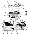
- a control unit is shown in a perspective view, as it is e.g. can be used to adjust heating, air conditioning and / or ventilation systems in motor vehicles.
- the embodiment shown here has two sliding links. With the help of these sliding elements, setting elements are usually actuated directly.
- the setting elements can be mechanical, e.g. Flaps, or electrical components, e.g. Motors, act. While the indirect actuation of the mechanical adjustment elements takes place via racks, cable drives, Bowden cables etc., the indirect actuation of the electrical adjustment elements is e.g. via potentiometers or switches operated by a slide. The level of the tapped voltage is a measure of the degree of adjustment.
- FIG. 1 denotes an elongated base body made of plastic with a U-shaped cross section, the reinforced side walls of which, as best seen in FIG. can be seen, each have an elongated recess 9.
- the reduction gear of a sliding member 4 is accommodated in each recess 9 and can be moved along the base body between two end positions.
- the sliding path of the sliding member 4 is limited by a projection 35 formed on the base body as a stop. Protrusions are expediently provided at both ends of the sliding path.
- the sliding member 4 consists of a U-shaped slide with a slide base 14.
- two holding members 15 are formed at a right angle to it, which on the front side of the slide base over a narrow Bridge 43 are connected to it in one piece.
- the holding members are resilient. This is important because there is a nose 16 at the free end of each holding member. After snapping in, these lugs serve to hold and guide the sliding member on the base body. The guidance takes place in such a way that the lugs 16 engage behind a web 17 which runs on the underside or rear of the base body 2 on the edge side.
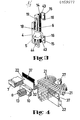
- the leg On the other side of the slide base, as shown in FIG. 3, the leg, which is at right angles, is formed by a first toothed rack which has internal teeth.
- a brake spring 19 is inserted into a depression 44 on the outside of the first rack 6. This brake spring is supported under pretension on the one hand on a wall of the recess 9 in the base body 2 and on the other hand on the sliding member 4 itself. With the preload, the desired sliding movement of the sliding member can be preselected within certain limits.
- an angle piece 18 is formed in alignment with it, which carries an actuating handle 5 at the angled, free end.
- the actuation handle 5 is laterally offset with respect to the slide base 14 and thus with respect to the part of the angle piece 18 which lies in the same plane as the slide base and extends through the slot formed between the base body 2 and the frame 3, so that a type of labyrinth seal is formed.
- a certain degree of protection of the interior against dirt is thereby achieved.
- another mechanical and electrical protection is given by the fact that you cannot get into the interior through the slot with a narrow object.
- the engine noise is dampened or, if you close the back of the control unit with a lid, greatly reduced.
- a linear drive with a reduction gear is located in the lateral recess 9 of the base body.
- This consists, among other things, of the first rack 6 of the sliding member 4 and a second rack 7, which, as shown in FIG. 2, on the lower wall of the recess 9 on the base body is trained.
- three gear wheels 8 are rotatably mounted between the two racks.
- Each gear 8 is attached to a pin 13, but so that it can rotate.
- the pins in turn are molded onto a rod 10 which is guided in a groove 11 on the bottom of the recess 9. As illustrated in FIG. 2, the pins 13 are perpendicular to the sliding direction of the rod 10.
- the gear wheels 8 rotate, the teeth of which engage both the teeth of the first rack 6 and the teeth of the second rack 7.
- the rod-e 10 also moves with the gearwheels. Due to this reduction gear, the sliding path of the rod is half the size of the sliding path of the sliding link. For this reason, the first rack 6 is approximately longer than half the sliding path of the sliding member 4. It is expedient to use at least three gear wheels in order to achieve a safe sliding gear. At the beginning and at the end of the sliding path of the sliding member in the vicinity of the stops, there are only two gears in each case in engagement with both racks. In the middle of the sliding path of the sliding member, the first rack 6 runs over all three gears.
- a Bowden cable can be connected to each rod 10.
- mechanical adjustment elements shown in the figures can be adjusted.
- an electrical connection can also be provided.
- the rod could e.g. be connected directly to the slide of a slide potentiometer.
- the voltage tapped by the contact spring is led via an electrical connection in the form of a printed circuit board or a cable directly or after conversion to an adjusting element which is adjusted according to the level of this voltage.
- the embodiment shown in Figure 1 has two sliding adjustment options, the base body 2 is covered by a frame 3 on the side and on the edge where the slot for the sliding member is located. If more than two sliding adjustment options are required, several base bodies can also be strung together and covered by a common frame, but always so that the existing slot is covered and protected by a frame web.
- a slot 31 extending in the sliding direction is recessed in the groove 11 at the bottom of the recess.
- a driver 32 which is integrally formed on the rod 10, projects into this slot 31.
- This driver 32 is located on the side of the rod opposite the pin 13.
- Connected to the driver 32 is an elongated sliding body 22, in the crack of which two ink ribbons 37 are clamped side by side.
- stiff color discs instead of ribbons, you could also use stiff color discs.
- the color display or the length of each ribbon is selected so that in the end positions of the sliding member, the light guide ends 24 visible in the frame 3 light up either only red or only blue.
- a lighting center 20 is arranged on the back of the U-shaped body? It consists, among other things, of an approximately rectangular socket body 25, which is made of plastic or metal. A semicircular depression 36 is cut out on the underside facing the base body. The light source 27, which is held in a lamp holder 28, projects into the hollow of this depression 36. This lamp holder can either be integrally formed on the holder body 25 or inserted as a separate lamp holder 28 in the holder body 25. The edge of the depression has many semicircular, radially running incisions 42. The light guides 21 are clamped into these incisions. The cross section of each light guide is rectangular with broad and long sides. The Light guides are arranged side by side so that their long sides lie close together. This allows them to optimally absorb a maximum of light.
- each ribbon is selected such that it is somewhat larger than the total distance of the light guides lying side by side. This ensures that all light guides light up in one color from the end stop.
- the furrow edge for the outgoing light guide is formed by a strip 38 in which the light guide is held.
- the socket body 25 and the strip 38 are fastened to the base body 2 by means of screws 39.
- the outgoing light guides which are led out of the bar are widened in spacing, bent at an angle of 90 and simultaneously rotated so that the broad ends of the light guide ends 24 lie side by side.
- the rotations of the light guides are of course different depending on their position in the row.
- the light guide ends 24 are visible in columns 30 on a long side of the frame 3 as a thermometer-scale display.
- a thermometer-scale display could also be on the other long side be provided in the same colors or in other colors. You would only need another lighting center for the other sliding link.
- a socket 29 is provided, by means of which the corresponding voltage for the light source 27 can be brought up.
- This socket can either be attached to the socket body as an individual part or it can be integrally formed with it.
- thermometer scale-like display it is often desirable to illuminate the entire front in a mostly white light.
- a recess 23 is provided on the front side of the base body 2, which receives a light guide body 33.
- the light guide body can be covered with a transparent film, if necessary, which is provided with a label and / or with symbols.
- the light guide body can consist of closely spaced individual light guides or a large single piece. You can choose between two design options for area lighting. Either elevations or incisions are made on the underside of the light guide body, at which the light is deflected and guided to the smooth surface.
- the light guide body receives the light from a light source 34, which e.g. designed as a sofa, as shown in FIG. 1, is located on a broad side of the base body.
Landscapes
- Engineering & Computer Science (AREA)
- Mechanical Engineering (AREA)
- Physics & Mathematics (AREA)
- Thermal Sciences (AREA)
- General Engineering & Computer Science (AREA)
- Chemical & Material Sciences (AREA)
- Combustion & Propulsion (AREA)
- Transportation (AREA)
- Mechanical Control Devices (AREA)
- Illuminated Signs And Luminous Advertising (AREA)
- Air-Conditioning For Vehicles (AREA)
- Transmission Devices (AREA)
Applications Claiming Priority (4)
| Application Number | Priority Date | Filing Date | Title |
|---|---|---|---|
| DE3336828 | 1983-10-10 | ||
| DE3336828 | 1983-10-10 | ||
| DE3409260 | 1984-03-14 | ||
| DE19843409260 DE3409260A1 (de) | 1983-10-10 | 1984-03-14 | Bedieneinheit |
Related Parent Applications (2)
| Application Number | Title | Priority Date | Filing Date |
|---|---|---|---|
| EP84110800A Division EP0137325A3 (fr) | 1983-10-10 | 1984-09-11 | Unité de commande |
| EP84110800.4 Division | 1984-09-11 |
Publications (2)
| Publication Number | Publication Date |
|---|---|
| EP0159577A2 true EP0159577A2 (fr) | 1985-10-30 |
| EP0159577A3 EP0159577A3 (fr) | 1986-01-15 |
Family
ID=25814738
Family Applications (2)
| Application Number | Title | Priority Date | Filing Date |
|---|---|---|---|
| EP84110800A Withdrawn EP0137325A3 (fr) | 1983-10-10 | 1984-09-11 | Unité de commande |
| EP85103872A Withdrawn EP0159577A3 (fr) | 1983-10-10 | 1984-09-11 | Unité de commande |
Family Applications Before (1)
| Application Number | Title | Priority Date | Filing Date |
|---|---|---|---|
| EP84110800A Withdrawn EP0137325A3 (fr) | 1983-10-10 | 1984-09-11 | Unité de commande |
Country Status (3)
| Country | Link |
|---|---|
| US (1) | US4646206A (fr) |
| EP (2) | EP0137325A3 (fr) |
| DE (2) | DE3409260A1 (fr) |
Cited By (2)
| Publication number | Priority date | Publication date | Assignee | Title |
|---|---|---|---|---|
| FR2709838A1 (fr) * | 1993-09-07 | 1995-03-17 | Sagem | Grappe de conduits optiques pour équipement de bord. |
| WO2014198470A1 (fr) * | 2013-06-13 | 2014-12-18 | Zf Friedrichshafen Ag | Commutateur multifonctions comportant un élément de commutation pouvant être actionné |
Families Citing this family (30)
| Publication number | Priority date | Publication date | Assignee | Title |
|---|---|---|---|---|
| DE3535881A1 (de) * | 1985-10-08 | 1987-04-16 | Preh Elektro Feinmechanik | Beleuchtungseinrichtung fuer eine frontplatte |
| US4850240A (en) * | 1988-04-04 | 1989-07-25 | Outboard Marine Corporation | Detented slide control assembly |
| DE3909645A1 (de) * | 1989-03-23 | 1990-10-04 | Preh Elektro Feinmechanik | Stellvorrichtung einer heizungs- oder lueftungsanlage eines kraftfahrzeuges |
| JP2594937Y2 (ja) * | 1990-02-19 | 1999-05-24 | 株式会社 東海理化電機製作所 | ヒータコントロールユニット |
| US5094302A (en) * | 1990-06-15 | 1992-03-10 | Laibe Supply Corporation | Drilling rig |
| US5531181A (en) * | 1994-03-28 | 1996-07-02 | Delco Electronics Corporation | Apparatus for illuminating instrument cluster pointers |
| US5671996A (en) * | 1994-12-30 | 1997-09-30 | Donnelly Corporation | Vehicle instrumentation/console lighting |
| US5596903A (en) * | 1995-04-20 | 1997-01-28 | Tuthill Corporation | Rotary to linear actuator |
| EP0807041A1 (fr) * | 1995-12-06 | 1997-11-19 | KÜSTER & Co. GmbH | Dispositif de compensation pour systeme de freinage actionne par des cables |
| US5881994A (en) * | 1996-06-11 | 1999-03-16 | Trw Inc. | Variable temperature control system for vehicles |
| DE19707170B4 (de) * | 1997-02-22 | 2006-12-28 | Valeo Klimasysteme Gmbh | Stufenschalter |
| FR2763027B1 (fr) * | 1997-05-12 | 1999-06-25 | Valeo Electronique | Perfectionnement aux tableaux de commande, plus particulierement pour installation de chauffage, ventilation et/ou climatisation de l'habitacle d'un vehicule automobile |
| DE19834374B4 (de) * | 1998-07-30 | 2004-03-04 | Preh-Werke Gmbh & Co. Kg | Drehknopf eines Steuergerätes |
| US6453991B1 (en) * | 1999-03-29 | 2002-09-24 | Calsonickansei Corporation | Automotive air conditioner |
| DE29906411U1 (de) * | 1999-04-10 | 2000-09-14 | Merten Gmbh & Co Kg | Schalttafel |
| US6471648B1 (en) * | 2000-07-17 | 2002-10-29 | Acuson Corporation | Medical diagnostic ultrasound imaging system with a rotatable user interface element having a non-rotatable indicator |
| JP2002172925A (ja) * | 2000-12-06 | 2002-06-18 | Tokai Rika Co Ltd | 車両用操作スイッチユニット |
| DE10205318B4 (de) * | 2002-02-08 | 2014-02-13 | Continental Automotive Gmbh | Beleuchtbares Bedienelement |
| DE10255480B3 (de) * | 2002-11-28 | 2004-03-04 | Preh-Werke Gmbh & Co. Kg | Bedienelement |
| US6941058B2 (en) * | 2003-08-14 | 2005-09-06 | Song-Po Shih | Driving device for handicraft with acousto-optic control and driven by batteries |
| US7784968B2 (en) * | 2003-08-21 | 2010-08-31 | Studer Professional Audio Systems Gmbh | Slide controller for an audio mixer |
| US7534001B2 (en) * | 2007-03-07 | 2009-05-19 | Ichia Technologies, Inc. | Light-guiding method of light-guiding plate and key pad assembly using the light-guiding plate |
| US20090093206A1 (en) * | 2007-10-09 | 2009-04-09 | Honda Motor Co., Ltd. | Onboard air conditioning system |
| KR101530333B1 (ko) * | 2009-10-06 | 2015-06-19 | 한라비스테온공조 주식회사 | 공조 장치의 도어 구동용 케이블 고정 구조 |
| US8220688B2 (en) * | 2009-12-24 | 2012-07-17 | Ethicon Endo-Surgery, Inc. | Motor-driven surgical cutting instrument with electric actuator directional control assembly |
| US8706310B2 (en) * | 2010-06-15 | 2014-04-22 | Redwood Systems, Inc. | Goal-based control of lighting |
| CN102878519B (zh) * | 2012-08-22 | 2014-06-18 | 杭州广安汽车电器有限公司 | 一种汽车空调控制器背光系统 |
| US20140209695A1 (en) * | 2013-01-30 | 2014-07-31 | Adjust A Vent, a partnership consisting of William E. Pickard, III and Richard D. Frank | Adjustable register vent and grill assembly designed to fit all size standard air distribution boot openings |
| DE102014201413A1 (de) * | 2014-01-27 | 2015-07-30 | Automotive Lighting Reutlingen Gmbh | Lichtleiter |
| DE102017205660B3 (de) | 2017-04-03 | 2018-08-02 | Stage Tec Entwicklungsgesellschaft Für Professionelle Audiotechnik Mbh | Bedienvorrichtung mit beleuchtetem Pegelsteller-Stellelement |
Family Cites Families (22)
| Publication number | Priority date | Publication date | Assignee | Title |
|---|---|---|---|---|
| US2732723A (en) * | 1956-01-31 | Automatic stroke-changing apparatus | ||
| US262020A (en) * | 1882-08-01 | Mechanical movement | ||
| AU58304B (en) * | 1904-06-01 | 1905-05-23 | Hankinson Alfred | Improvements in miner's safety lamps |
| US2613630A (en) * | 1947-01-22 | 1952-10-14 | Gen Electric | Control device |
| US2772574A (en) * | 1952-12-22 | 1956-12-04 | John V Thomas | Stroke changing mechanism |
| US3191669A (en) * | 1962-05-21 | 1965-06-29 | Dale E Johnson | Automatic vehicle temperature control |
| US3298172A (en) * | 1964-12-31 | 1967-01-17 | Arthur I Bodkins | Illuminated display means |
| DE1580098C3 (de) * | 1966-08-30 | 1974-06-12 | Max Kammerer Gmbh, 6370 Oberursel | Vorrichtung zum Betätigen von Bowdenzügen, mit beleuchteter Anzeige der jeweiligen Betriebsstellung der Bedienungsorgane, insbesondere für Kraftfahrzeuge |
| US3755662A (en) * | 1971-07-14 | 1973-08-28 | Gen Motors Corp | Phase lighting heater and heater a/c control units |
| IT1031251B (it) * | 1975-01-29 | 1979-04-30 | Mecanique Ind Int | Dispositivo per contrassegnare differsenti posizioni oper ative di un organo di comando mediante illuminazione con differenti colori |
| DE7634978U1 (de) * | 1976-11-04 | 1978-03-16 | Siemens Ag, 1000 Berlin Und 8000 Muenchen | Blendeneinheit, insbesondere fuer armaturenbretter von kraftfahrzeugen |
| US4222435A (en) * | 1977-04-19 | 1980-09-16 | Mitsubishi Jidosha Kogyo Kabushiki Kaisha | Air conditioning display system for vehicles |
| US4257084A (en) * | 1979-02-21 | 1981-03-17 | Reynolds Christopher H | Display device |
| FR2472135A1 (fr) * | 1979-12-20 | 1981-06-26 | Cibie Projecteurs | Projecteur, notamment pour vehicules automobiles |
| JPS5697111U (fr) * | 1979-12-25 | 1981-08-01 | ||
| DE8004562U1 (de) * | 1980-02-21 | 1980-05-14 | Vdo Adolf Schindling Ag, 6000 Frankfurt | Lichtleitstab zum farbigen ausleuchten von kombiinstrumenten in kraftfahrzeugen |
| FR2503059A1 (fr) * | 1981-04-07 | 1982-10-08 | Renault | Dispositif de commande a distance a partir d'un tableau de bord, en particulier pour vehicule automobile |
| DE3125093A1 (de) * | 1981-06-26 | 1983-01-13 | Daimler-Benz Ag, 7000 Stuttgart | "mit einem stellschieber versehene verstelleinrichtung" |
| DE3206288A1 (de) * | 1982-02-22 | 1983-09-01 | Siemens AG, 1000 Berlin und 8000 München | Steuergeraet mit beleuchteten betaetigungsknoepfen fuer heizungs-, klima- und lueftungsanlagen in kraftfahrzeugen |
| DE3211319A1 (de) * | 1982-03-26 | 1983-09-29 | Siemens AG, 1000 Berlin und 8000 München | Schieberregler |
| DE8312000U1 (de) * | 1983-04-22 | 1983-07-21 | Süddeutsche Kühlerfabrik Julius Fr. Behr GmbH & Co KG, 7000 Stuttgart | Mehrstufiger Bedienungsschalter, insbesondere für Heizungs- und Lüftungsgebläse |
| DE3317807A1 (de) * | 1983-05-17 | 1984-11-22 | Preh, Elektrofeinmechanische Werke Jakob Preh Nachf. Gmbh & Co, 8740 Bad Neustadt | Leuchtbandanzeigeanordnung |
-
1984
- 1984-03-14 DE DE19843409260 patent/DE3409260A1/de active Granted
- 1984-04-30 DE DE3416024A patent/DE3416024A1/de active Granted
- 1984-09-11 EP EP84110800A patent/EP0137325A3/fr not_active Withdrawn
- 1984-09-11 EP EP85103872A patent/EP0159577A3/fr not_active Withdrawn
- 1984-10-09 US US06/658,487 patent/US4646206A/en not_active Expired - Fee Related
Cited By (2)
| Publication number | Priority date | Publication date | Assignee | Title |
|---|---|---|---|---|
| FR2709838A1 (fr) * | 1993-09-07 | 1995-03-17 | Sagem | Grappe de conduits optiques pour équipement de bord. |
| WO2014198470A1 (fr) * | 2013-06-13 | 2014-12-18 | Zf Friedrichshafen Ag | Commutateur multifonctions comportant un élément de commutation pouvant être actionné |
Also Published As
| Publication number | Publication date |
|---|---|
| EP0159577A3 (fr) | 1986-01-15 |
| US4646206A (en) | 1987-02-24 |
| EP0137325A2 (fr) | 1985-04-17 |
| DE3409260C2 (fr) | 1990-12-06 |
| DE3416024C2 (fr) | 1988-11-17 |
| EP0137325A3 (fr) | 1986-01-08 |
| DE3409260A1 (de) | 1985-04-11 |
| DE3416024A1 (de) | 1985-10-31 |
Similar Documents
| Publication | Publication Date | Title |
|---|---|---|
| DE3416024C2 (fr) | ||
| DE3434302C2 (fr) | ||
| DE2424376A1 (de) | Anzeigevorrichtung | |
| EP0129662B1 (fr) | Dispositif indicateur par bande luminescente | |
| DE69400273T2 (de) | Getriebegang-Anzeige für die Betätigungseinrichtung in einem Automatikgetriebe | |
| WO2008006593A1 (fr) | Dispositif de visualisation pour automobile. à faisceau lumineux sensiblement parallèle | |
| DE102012024667B4 (de) | Beleuchtungseinrichtung für ein Fahrzeuginneneinrichtungsteil | |
| DE3019021A1 (de) | Beleuchtungseinrichtung fuer einen drucktastenschalter | |
| DE102008064283B3 (de) | Optische Sollwertanzeigevorrichtung für eine Fahrzeugkomponente | |
| DE102017119618A1 (de) | Luftleitanordnung | |
| DE3909645C2 (fr) | ||
| DE3533056A1 (de) | Mehrstufiger, beleuchteter schalter an kraftfahrzeugen | |
| DE19542913C2 (de) | Beleuchtbare Bedienelementanordnung | |
| DE3246985C2 (fr) | ||
| EP0590170B1 (fr) | Dispositif d'affichage, notamment face avant d'un appareil de commande dans un véhicule automobile | |
| DE2804604B1 (de) | Flexible Abdeckung fuer einen Konsolenschacht,insbesondere in Kraftfahrzeugen | |
| DE19708064B4 (de) | Bedieneinrichtung | |
| DE3137975C2 (fr) | ||
| DE68903151T2 (de) | Bedienungsfeld fuer eine fahrzeugklimaanlage. | |
| DE2851998C2 (de) | Beleuchteter Installationsschalter | |
| DE3546625C2 (en) | Electrical rotary switch having illumination | |
| DE3621438A1 (de) | Bedien- und anzeigevorrichtung fuer hausgeraete | |
| DE3005457A1 (de) | Schalterbetaetigungsorgan mit mechanischer anzeigevorrichtung fuer den schaltzustand eines schalters | |
| DE1580098C3 (de) | Vorrichtung zum Betätigen von Bowdenzügen, mit beleuchteter Anzeige der jeweiligen Betriebsstellung der Bedienungsorgane, insbesondere für Kraftfahrzeuge | |
| DE4420626C2 (de) | Leistenförmige Betätigungseinrichtung für einen Fahrzeugsitz |
Legal Events
| Date | Code | Title | Description |
|---|---|---|---|
| PUAI | Public reference made under article 153(3) epc to a published international application that has entered the european phase |
Free format text: ORIGINAL CODE: 0009012 |
|
| AC | Divisional application: reference to earlier application |
Ref document number: 137325 Country of ref document: EP |
|
| AK | Designated contracting states |
Designated state(s): AT BE CH FR GB IT LI LU NL SE |
|
| PUAL | Search report despatched |
Free format text: ORIGINAL CODE: 0009013 |
|
| AK | Designated contracting states |
Designated state(s): AT BE CH FR GB IT LI LU NL SE |
|
| 17P | Request for examination filed |
Effective date: 19860203 |
|
| 17Q | First examination report despatched |
Effective date: 19860806 |
|
| STAA | Information on the status of an ep patent application or granted ep patent |
Free format text: STATUS: THE APPLICATION HAS BEEN WITHDRAWN |
|
| 18W | Application withdrawn |
Withdrawal date: 19861022 |
|
| RIN1 | Information on inventor provided before grant (corrected) |
Inventor name: WOLF, REINHOLD Inventor name: BAUER, KARL-HEINZ |