EP0159647B1 - Dispositif pour la séparation des particules d'un aérosol en classes granulométriques - Google Patents
Dispositif pour la séparation des particules d'un aérosol en classes granulométriques Download PDFInfo
- Publication number
- EP0159647B1 EP0159647B1 EP85104542A EP85104542A EP0159647B1 EP 0159647 B1 EP0159647 B1 EP 0159647B1 EP 85104542 A EP85104542 A EP 85104542A EP 85104542 A EP85104542 A EP 85104542A EP 0159647 B1 EP0159647 B1 EP 0159647B1
- Authority
- EP
- European Patent Office
- Prior art keywords
- plate
- annular
- cavity
- groove
- fact
- Prior art date
- Legal status (The legal status is an assumption and is not a legal conclusion. Google has not performed a legal analysis and makes no representation as to the accuracy of the status listed.)
- Expired
Links
- 239000002245 particle Substances 0.000 title claims description 63
- 238000000926 separation method Methods 0.000 title description 13
- 230000005855 radiation Effects 0.000 claims description 3
- 238000004347 surface barrier Methods 0.000 claims description 2
- 238000011044 inertial separation Methods 0.000 claims 1
- 239000000443 aerosol Substances 0.000 description 12
- 239000012530 fluid Substances 0.000 description 10
- 238000010586 diagram Methods 0.000 description 6
- 239000000428 dust Substances 0.000 description 6
- 230000008021 deposition Effects 0.000 description 5
- 238000000034 method Methods 0.000 description 5
- 230000002093 peripheral effect Effects 0.000 description 4
- 230000005183 environmental health Effects 0.000 description 3
- 238000010521 absorption reaction Methods 0.000 description 2
- 238000004458 analytical method Methods 0.000 description 2
- 238000004891 communication Methods 0.000 description 2
- 230000000694 effects Effects 0.000 description 2
- 239000000126 substance Substances 0.000 description 2
- 230000001988 toxicity Effects 0.000 description 2
- 231100000419 toxicity Toxicity 0.000 description 2
- 239000004809 Teflon Substances 0.000 description 1
- 229920006362 Teflon® Polymers 0.000 description 1
- 229920002678 cellulose Polymers 0.000 description 1
- 239000001913 cellulose Substances 0.000 description 1
- 230000003247 decreasing effect Effects 0.000 description 1
- 230000008030 elimination Effects 0.000 description 1
- 238000003379 elimination reaction Methods 0.000 description 1
- 238000005516 engineering process Methods 0.000 description 1
- 230000007613 environmental effect Effects 0.000 description 1
- 238000004519 manufacturing process Methods 0.000 description 1
- 239000012528 membrane Substances 0.000 description 1
- 239000011148 porous material Substances 0.000 description 1
- 239000000843 powder Substances 0.000 description 1
- 238000005070 sampling Methods 0.000 description 1
- 239000007787 solid Substances 0.000 description 1
- 239000000725 suspension Substances 0.000 description 1
Images
Classifications
-
- G—PHYSICS
- G01—MEASURING; TESTING
- G01N—INVESTIGATING OR ANALYSING MATERIALS BY DETERMINING THEIR CHEMICAL OR PHYSICAL PROPERTIES
- G01N15/00—Investigating characteristics of particles; Investigating permeability, pore-volume or surface-area of porous materials
- G01N15/02—Investigating particle size or size distribution
- G01N15/0272—Investigating particle size or size distribution with screening; with classification by filtering
-
- G—PHYSICS
- G01—MEASURING; TESTING
- G01N—INVESTIGATING OR ANALYSING MATERIALS BY DETERMINING THEIR CHEMICAL OR PHYSICAL PROPERTIES
- G01N15/00—Investigating characteristics of particles; Investigating permeability, pore-volume or surface-area of porous materials
- G01N15/06—Investigating concentration of particle suspensions
- G01N15/0606—Investigating concentration of particle suspensions by collecting particles on a support
- G01N15/0618—Investigating concentration of particle suspensions by collecting particles on a support of the filter type
-
- G—PHYSICS
- G01—MEASURING; TESTING
- G01N—INVESTIGATING OR ANALYSING MATERIALS BY DETERMINING THEIR CHEMICAL OR PHYSICAL PROPERTIES
- G01N15/00—Investigating characteristics of particles; Investigating permeability, pore-volume or surface-area of porous materials
- G01N2015/0042—Investigating dispersion of solids
- G01N2015/0046—Investigating dispersion of solids in gas, e.g. smoke
Definitions
- the present invention relates to a device of improved type for the separation of airborne particles such as an aerosol, into grain size classes.
- a device is an instrument which permits the deposition onto a filter of dust particles on which it is then possible to perform a series of chemical and physico-chemical analyses in dependence on the dimensions thereof, for the purpose of determining the risk from inhalation of dust present in a predetermined environment.
- Like devices are also described in the co-pending European Patent applications Nos.
- the object of the present invention is that of providing a device of improved type for the separation of airborne particles into grain size classes, which will be free from the said disadvantages and which, that is to say, will permit the separation of even particles of smaller diameter into different grain size classes thereby allowing a linearisation of the curve of the first mentioned diagram to be obtained even for that portion of the curve relating to the particles of smaller diameter.
- the present invention is characterized by Claim 1.
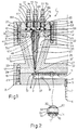
- a device of improved type for the separation of aerosol particles into grain size classes is generally indicated with the reference numeral 1.
- the device 1 has a cylindrical base body 2 on the upper surface of which is formed a cylindrical cavity 3.
- a threaded through hole 4 into which is screwed an upper threaded portion 5 of a pipe union 6 a lower portion 7 of which projects out from the body 2 from the lower surface of this.
- the pipe union 6 is in communication via a duct not illustrated with a pump able to create a depression in the cavity 3.
- annular rebate 8 upon which rests the perimetral edge of a cylindrical plate 11 on which, with the interposition of a mesh 12 of circular outline ( Figure 2), there is deposited a filter 13 also of circular outline.
- a plurality of concentric annular grooves 14 On the upper surface of the plate 11 there are formed a plurality of concentric annular grooves 14. Along each groove 14 there is formed a plurality of through holes 15 the axes of which are orthogonal to the longitudinal axis of the groove 14. In use, the fluid composed of filtered air and aerosol, stripped of the particles which have been deposited on the filter, pass through this latter and enter the cavity 3 by passing through the groove 14 and the holes 15.
- the thickness of the assembly comprising the plate 11, mesh 12 and filter 13 is equal to the vertical depth of the recess 8 in such a way that the upper surface of the filter 13 is coplanar with the upper surface of the body 2.
- the filter 13 is preferably of the membrane type, that is to say formed with a porous material such as cellulose or Teflon°.
- the device 1 includes an annular body 17 coaxial with the body 2 and in fact fixed to this latter by screws 18.
- the body 17 has a central portion 21 of substantially frusto-conical form and of constant thickness positioned with the larger diameter end uppermost.
- annular projection 22 extends radially outwardly, this projection having its lower surface facing a peripheral region of the upper surface of the body 2.
- This latter has a plurality of through holes 23 coaxial with a corresponding number of blind threaded holes 24 formed in the projection 22.
- the screws 18 first engage the holes 23 and subsequently are screwed into the holes 24.
- a second annular projection 25 extends outwardly parallel to the projection 22.
- the device 1 further includes an annular body 27 coaxial with the body 17 and rather inward of this latter.
- the body 27 has a central portion 28 of substantially frusto-conical form, of constant thickness, and having the lower end of greater diameter.
- the inner surface of the portion 21 of the body 17 and the outer surface of the portion 28 of the body 27 define an annular channel 31 having a width decreasing from the top towards the bottom.
- the lower end of the portion 28 joins to the perimetral edge of a cylindrical base wall 32 having a thickness less than that of the projection 22, that is to say with its lower surface facing but at a predetermined distance from the upper surface of the filter 13 which has already been indicated is coplanar with the upper surface of the bdoy 2.
- a cylindrical cavity 33 of reduced depth Between the lower surface of the wall 32 and the upper surface of the filter 13 there is therefore defined a cylindrical cavity 33 of reduced depth.
- the assembly comprising the plate 11, mesh 12 and filter 13 is therefore a dividing wall between the cavities 3 and 33.
- the cavity 33 is in communication with the channel 31 by the fact that the lower ends of the portions 21 and 28 lie at a predetermined small distance from one another. As illustrated in the drawings, it is to be noted that the said ends do not have sharp corners since these are suitably rounded or bevelled.
- the space within the channel 31 defined by the said ends of the portions 21 and 28 will hereinafter be called the outlet and indicated 31'. From the upper end of the portion 28 an annular projection 34 extends inwardly coplanar with the projection 25.
- the device 1 includes two annular plates 36 and 37 coaxial with one another and with the bodies 17 and 24.
- the radially inner ring of the plates 36 and 37 are fixed by screws 38 to the projection 34 of the body 27 and their radially outer rims are fixed by screws 40 to the projection 25 of the body 17.
- the plate 36 rests directly on the upper surface of the projections 25 and 34 and in this connection has on the inner peripheral region a plurality of through holes 41 and on the outer peripheral region a plurality of through holes 42.
- the holes 41 are coaxial with corresponding threaded blind holes 43 formed in the projection 34 and the holes 42 are coaxial with corresponding threaded blind holes 44 formed in the projection 25.
- the central ring of the plate 36 has a greater thickness than the inner and outer rims.
- the inner and outer edges of this central ring rest respectively on an annular rebate 45 formed at the upper end of the portion 28 and on the annular rebate 46 formed at the upper end of the portion 21.
- the lower surface of the central ring of the plate 36 faces the channel 31 and has three annular grooves respectively indicated 47, 48 and 51.
- the grooves 47 and 51 are respectively the innermost and the outermost and have the same width.
- the groove 48 which is the central groove, has a greater width than the others and houses the upper end of a nozzle 52 constituted by two annular bodies 53 and 54 coaxial with one another and to the bodies 17 and 27.
- the bodies 53 and 54 are concentric and define between them an annular channel 55.
- the bodies 53 and 54, of which that indicated 53 is inside the other are fixed to the plate 36 with their upper ends by means of a plurality of screws 56 of which, for simplicity, only one is illustrated in Figure 1, and which fix the body 54 to the plate 36.
- the holes 57 open below into the channel 55.
- the plate 37 rests on the plate 36 and has an inner ring of through holes 63 coaxial with the holes 41 and an outer ring of through holes 64 coaxial with the holes 42.
- Each screw 38 engages in succession the hole 63 and the hole 41 and is screwed into the hole 43.
- Each screw 40 engages in succession the hole 64 and the hole 42 and is screwed into the hole 44.
- the central ring of the plate 37 which is in correspondence with the central ring of the plate 36 has on its lower surface three annular grooves 65, 66 and 67 of which the groove 65 which is the innermost is formed in correspondence with the holes 58, the groove 66, which is the central one, is formed in correspondence wpth the holes 57, and the groove 67, which is the outermost, is formed in corresepondence with the hole 61.
- the groove 66 on the plate 37 there are formed threaded holes 68 into which there is screwed the lower threaded part 71 of a respective pipe union 72 having an upper part 73 extending upwardly out from the hole 68.
- the pipe unions 72 are connected by ducts not illustrated to a source of aerosol (particle-bearing air) and the pipe unions 76 are connected to a source of filtered air by respective ducts not illustrated.
- the operation of the device 1 is as follows.
- constant quantity of filtered air is injected into the channel 31 from a suitable source and a constant quantity of dust-bearing air or aerosol is ejected, via the nozzle 52, into the channel 31 in correspondence with the outlet 31' from a second source which could be the environment itself.
- This is possible, for example, by connecting the pipe union 6 and therefore the interior of the cavity 3 with a pump able to create a depression in the cavity 3 which draws in the filtered air and the aerosol.
- an aerosol is simply air in which there are present particles in suspension. The fluid constituted by the filtered air and the particle-bearing air is subsequently introduced into the cavity 33.
- the device 1 with the circular filter 13 permits an elongation of the zone of separation of the particles, the elimination of the side walls of the cavity 33, and a greater linearisation of the curve obtained in a diagram which plots in abscissae the distance of the deposition starting from the curvature (outlet 31') and along the ordinate the aerodynamic diameter of the particles.
- the aerodynamic separation of the particles in fact permits the mass, activity, form, density and other characteristics of the particles themselves to be studied.
- the interposition of the mesh 12 between the filter 13 and the plate 11 permits the particles to be deposited on the whole of the filter 13, that is to say even in those portions of the filter 13 corresponding to the solid parts of the plate 11 between two contiguous grooves 14.
Landscapes
- Chemical & Material Sciences (AREA)
- Dispersion Chemistry (AREA)
- Physics & Mathematics (AREA)
- Health & Medical Sciences (AREA)
- Life Sciences & Earth Sciences (AREA)
- Analytical Chemistry (AREA)
- Biochemistry (AREA)
- General Health & Medical Sciences (AREA)
- General Physics & Mathematics (AREA)
- Immunology (AREA)
- Pathology (AREA)
- Sampling And Sample Adjustment (AREA)
- Threshing Machine Elements (AREA)
Claims (12)
un troisième corps (27) logé à l'intérieure dudit deuxième corps (17) et possédant une paroi de base (32) face à ladite plaque (11) et dont la surface inférieure définit, avec la surface supérieure dudit filtre (13), une deuxième cavité cylindrique (33), de profondeur réduite, constituant une deuxième partie dudit système d'amenée, et une partie centrale (28) s'étendant vers le haut à partir du bord latéral de ladite paroi de fond (32) et constituant par sa surface extérieure la surface latérale d'un corps tronconique dont la partie de plus grand diamètre est située à la partie inférieure de façon à constituer, avec la surface intérieure de ladite partie centrale (21) dudit deuxième corps (17), un canal annulaire (31) de section transversale triangulaire communiquant avec ladite deuxième cavité (33) par une sortie (31') réalisée en joignant de façon appropriée les extrémités inférieures desdites parties centrales (21 et 28) respectivement desdits deuxième (17) et troisième (27) corps, ladite sortie formant un coude brusque pour séparer, lors de l'utilisation du dispositif, les particules qui passent le long du coude selon leur diamètre aérodynamique, ledit canal annulaire (31) étant susceptible d'amener de l'air filtré dans ladite deuxième cavité (33); et un ajutage annulaire (52) placé dans ledit canal annulaire (31) fonctionnant pour y éjecter près de ladite sortie (31'), une quantité d'air portant des particules.
Applications Claiming Priority (2)
| Application Number | Priority Date | Filing Date | Title |
|---|---|---|---|
| IT343284 | 1984-04-19 | ||
| IT03432/84A IT1199393B (it) | 1984-04-19 | 1984-04-19 | Dispositivo di tipo perfezionato per la separazione in classi granulometriche di particelle di aerosol |
Publications (2)
| Publication Number | Publication Date |
|---|---|
| EP0159647A1 EP0159647A1 (fr) | 1985-10-30 |
| EP0159647B1 true EP0159647B1 (fr) | 1989-10-11 |
Family
ID=11107262
Family Applications (1)
| Application Number | Title | Priority Date | Filing Date |
|---|---|---|---|
| EP85104542A Expired EP0159647B1 (fr) | 1984-04-19 | 1985-04-15 | Dispositif pour la séparation des particules d'un aérosol en classes granulométriques |
Country Status (5)
| Country | Link |
|---|---|
| US (1) | US4704528A (fr) |
| EP (1) | EP0159647B1 (fr) |
| JP (1) | JPS6122232A (fr) |
| DE (1) | DE3573658D1 (fr) |
| IT (1) | IT1199393B (fr) |
Families Citing this family (1)
| Publication number | Priority date | Publication date | Assignee | Title |
|---|---|---|---|---|
| US5026994A (en) * | 1990-08-06 | 1991-06-25 | Rad-X Ltd. | Method and apparatus for measuring the size distribution of particles |
Family Cites Families (6)
| Publication number | Priority date | Publication date | Assignee | Title |
|---|---|---|---|---|
| US3952207A (en) * | 1973-02-01 | 1976-04-20 | Leschonski K | Method and means for determination of particle size distributions in a mass flow of a granular material |
| US3854321A (en) * | 1973-04-27 | 1974-12-17 | B Dahneke | Aerosol beam device and method |
| IT1115883B (it) * | 1977-07-21 | 1986-02-10 | Cnen | Dispositivo impattore per la separazione delle particelle di aerosol in classi granulometriche |
| US4213852A (en) * | 1979-01-15 | 1980-07-22 | Bernard Etkin | Method and apparatus for particle classification |
| US4298836A (en) * | 1979-11-23 | 1981-11-03 | Coulter Electronics, Inc. | Particle shape determination |
| IT1179318B (it) * | 1984-04-19 | 1987-09-16 | Vittorio Prodi | Dispositivo per la ripartizione in classi granulometriche di particelle di aerosol |
-
1984
- 1984-04-19 IT IT03432/84A patent/IT1199393B/it active
-
1985
- 1985-04-15 EP EP85104542A patent/EP0159647B1/fr not_active Expired
- 1985-04-15 DE DE8585104542T patent/DE3573658D1/de not_active Expired
- 1985-04-16 US US06/723,742 patent/US4704528A/en not_active Expired - Fee Related
- 1985-04-18 JP JP60081497A patent/JPS6122232A/ja active Pending
Also Published As
| Publication number | Publication date |
|---|---|
| JPS6122232A (ja) | 1986-01-30 |
| US4704528A (en) | 1987-11-03 |
| EP0159647A1 (fr) | 1985-10-30 |
| IT8403432A0 (it) | 1984-04-19 |
| IT1199393B (it) | 1988-12-30 |
| DE3573658D1 (en) | 1989-11-16 |
Similar Documents
| Publication | Publication Date | Title |
|---|---|---|
| US4133202A (en) | Multiple nozzle single stage impactor | |
| US5412975A (en) | Universal inlet for airborne-particle size-selective sampling | |
| US6010554A (en) | Micro-machined virtual impactor and method of operation | |
| US11730393B2 (en) | Device for collecting particles in an exhaled air flow | |
| US3854321A (en) | Aerosol beam device and method | |
| DE2917004A1 (de) | Verfahren und einrichtung zur abschirmung gesundheitsschaedlicher substanzen | |
| DE3118878C2 (de) | Prüfröhrchen | |
| EP0159646B1 (fr) | Dispositif pour la séparation des particules d'un aérosol en classes granulométriques | |
| US5702506A (en) | Method and device for aerosol size-selective sampling | |
| US4255172A (en) | Jet impaction preseparator | |
| US4704528A (en) | Device for the separation of airborne particles into classes by grain size | |
| US4400982A (en) | High volume particle collector and fractionator | |
| US4639311A (en) | Device for separating airborne particles into grain size classes | |
| DE2947302A1 (de) | Verfahren zum nachweis von in einem vorgegebenen energiebereich liegenden (alpha)-strahlen | |
| US2879664A (en) | Annular impactor sampling device | |
| EP0159648B1 (fr) | Dispositif pour la séparation des particules d'un aérosol en classes granulométriques | |
| EP4583772B1 (fr) | Dispositif de collecte de particules dans un flux d'air expiré et procédé d'extraction de particules collectées | |
| US3294236A (en) | Method for pneumatically elutriating solid particles | |
| HU180980B (en) | Three-stage liquid trap | |
| JPH0425635Y2 (fr) | ||
| US3724658A (en) | Particle separation in a gaseous fluid | |
| SU836090A1 (ru) | Устройство дл дисперсионного исследовани бАКТЕРиАльНыХ АэРОзОлЕй | |
| Stoeber et al. | Aerosol size spectrometry with a ring slit conifuge | |
| Pyne et al. | Air filtration by moving filaments | |
| RU2251679C2 (ru) | Импактор |
Legal Events
| Date | Code | Title | Description |
|---|---|---|---|
| PUAI | Public reference made under article 153(3) epc to a published international application that has entered the european phase |
Free format text: ORIGINAL CODE: 0009012 |
|
| AK | Designated contracting states |
Designated state(s): DE FR GB NL |
|
| 17P | Request for examination filed |
Effective date: 19860312 |
|
| 17Q | First examination report despatched |
Effective date: 19871007 |
|
| GRAA | (expected) grant |
Free format text: ORIGINAL CODE: 0009210 |
|
| AK | Designated contracting states |
Kind code of ref document: B1 Designated state(s): DE FR GB NL |
|
| REF | Corresponds to: |
Ref document number: 3573658 Country of ref document: DE Date of ref document: 19891116 |
|
| ET | Fr: translation filed | ||
| PLBE | No opposition filed within time limit |
Free format text: ORIGINAL CODE: 0009261 |
|
| STAA | Information on the status of an ep patent application or granted ep patent |
Free format text: STATUS: NO OPPOSITION FILED WITHIN TIME LIMIT |
|
| 26N | No opposition filed | ||
| PGFP | Annual fee paid to national office [announced via postgrant information from national office to epo] |
Ref country code: FR Payment date: 19920327 Year of fee payment: 8 |
|
| PGFP | Annual fee paid to national office [announced via postgrant information from national office to epo] |
Ref country code: GB Payment date: 19920403 Year of fee payment: 8 |
|
| PGFP | Annual fee paid to national office [announced via postgrant information from national office to epo] |
Ref country code: DE Payment date: 19920429 Year of fee payment: 8 |
|
| PGFP | Annual fee paid to national office [announced via postgrant information from national office to epo] |
Ref country code: NL Payment date: 19920430 Year of fee payment: 8 |
|
| PG25 | Lapsed in a contracting state [announced via postgrant information from national office to epo] |
Ref country code: GB Effective date: 19930415 |
|
| PG25 | Lapsed in a contracting state [announced via postgrant information from national office to epo] |
Ref country code: NL Effective date: 19931101 |
|
| GBPC | Gb: european patent ceased through non-payment of renewal fee |
Effective date: 19930415 |
|
| NLV4 | Nl: lapsed or anulled due to non-payment of the annual fee | ||
| PG25 | Lapsed in a contracting state [announced via postgrant information from national office to epo] |
Ref country code: FR Effective date: 19931229 |
|
| PG25 | Lapsed in a contracting state [announced via postgrant information from national office to epo] |
Ref country code: DE Effective date: 19940101 |
|
| REG | Reference to a national code |
Ref country code: FR Ref legal event code: ST |