EP0159818B1 - Procédé et appareil pour la fabrication de produits métalliques - Google Patents
Procédé et appareil pour la fabrication de produits métalliques Download PDFInfo
- Publication number
- EP0159818B1 EP0159818B1 EP85302018A EP85302018A EP0159818B1 EP 0159818 B1 EP0159818 B1 EP 0159818B1 EP 85302018 A EP85302018 A EP 85302018A EP 85302018 A EP85302018 A EP 85302018A EP 0159818 B1 EP0159818 B1 EP 0159818B1
- Authority
- EP
- European Patent Office
- Prior art keywords
- work rolls
- metal
- rolls
- plate
- rolled
- Prior art date
- Legal status (The legal status is an assumption and is not a legal conclusion. Google has not performed a legal analysis and makes no representation as to the accuracy of the status listed.)
- Expired
Links
Images



Classifications
-
- B—PERFORMING OPERATIONS; TRANSPORTING
- B21—MECHANICAL METAL-WORKING WITHOUT ESSENTIALLY REMOVING MATERIAL; PUNCHING METAL
- B21H—MAKING PARTICULAR METAL OBJECTS BY ROLLING, e.g. SCREWS, WHEELS, RINGS, BARRELS, BALLS
- B21H7/00—Making articles not provided for in the preceding groups, e.g. agricultural tools, dinner forks, knives, spoons
- B21H7/16—Making articles not provided for in the preceding groups, e.g. agricultural tools, dinner forks, knives, spoons turbine blades; compressor blades; propeller blades
-
- B—PERFORMING OPERATIONS; TRANSPORTING
- B21—MECHANICAL METAL-WORKING WITHOUT ESSENTIALLY REMOVING MATERIAL; PUNCHING METAL
- B21B—ROLLING OF METAL
- B21B13/00—Metal-rolling stands, i.e. an assembly composed of a stand frame, rolls, and accessories
- B21B13/02—Metal-rolling stands, i.e. an assembly composed of a stand frame, rolls, and accessories with axes of rolls arranged horizontally
- B21B2013/025—Quarto, four-high stands
-
- B—PERFORMING OPERATIONS; TRANSPORTING
- B21—MECHANICAL METAL-WORKING WITHOUT ESSENTIALLY REMOVING MATERIAL; PUNCHING METAL
- B21B—ROLLING OF METAL
- B21B27/00—Rolls, roll alloys or roll fabrication; Lubricating, cooling or heating rolls while in use
- B21B27/02—Shape or construction of rolls
-
- B—PERFORMING OPERATIONS; TRANSPORTING
- B21—MECHANICAL METAL-WORKING WITHOUT ESSENTIALLY REMOVING MATERIAL; PUNCHING METAL
- B21B—ROLLING OF METAL
- B21B37/00—Control devices or methods specially adapted for metal-rolling mills or the work produced thereby
- B21B37/16—Control of thickness, width, diameter or other transverse dimensions
- B21B37/24—Automatic variation of thickness according to a predetermined program
-
- B—PERFORMING OPERATIONS; TRANSPORTING
- B21—MECHANICAL METAL-WORKING WITHOUT ESSENTIALLY REMOVING MATERIAL; PUNCHING METAL
- B21B—ROLLING OF METAL
- B21B39/00—Arrangements for moving, supporting, or positioning work, or controlling its movement, combined with or arranged in, or specially adapted for use in connection with, metal-rolling mills
- B21B39/34—Arrangements or constructional combinations specifically designed to perform functions covered by more than one of groups B21B39/02, B21B39/14, B21B39/20
-
- B—PERFORMING OPERATIONS; TRANSPORTING
- B60—VEHICLES IN GENERAL
- B60G—VEHICLE SUSPENSION ARRANGEMENTS
- B60G2206/00—Indexing codes related to the manufacturing of suspensions: constructional features, the materials used, procedures or tools
- B60G2206/01—Constructional features of suspension elements, e.g. arms, dampers, springs
- B60G2206/80—Manufacturing procedures
- B60G2206/81—Shaping
- B60G2206/8109—Shaping by rolling
Definitions
- This invention relates to the production of metal flat products having more than one thickness or which vary in thickness in a controlled manner. It has particular but not necessarily exclusive reference to the manufacture of such plates in titanium, aluminium, nickel, iron or alloys based on such metals.
- Titanium alloys are expensive to produce and this is particularly so in the case of titanium alloys used in aero-engine components. Because of the need for extremely high levels of integrity in such parts the quality control required to produce the metal is so high that it adds significantly to the expense. As the parts are frequently of a complex shape it is often necessary to carry out extensive machining of the starting material and these machining operations produce large quantities of waste scrap which has little value.
- the blades essentially comprise a relatively thin sheet of metal having a thickened end portion which is machined or forged to form a root which is attached to a suitable disc. It would obviously be possible to produce the root by starting with a thick plate and machining away all of the excess material to manufacture the thin sheet leaving the thickened end portion to form the root, the thickened end portion having the thickness of the original plate. Such a machining operation would, however, be very expensive and the yield would be very low.
- the work rolls are adapted to rotate in use in one direction only, the arrangement being such that metal to be rolled is fed into the work rolls from one side and feeds through the rolls to be rolled and to be discharged from the nip of the rolls on the opposite side to the side into which it was fed.
- the end stop against which the leading end of the metal is located prior to rotation of the work rolls for rolling, part at least of the metal being accommodated within the recess.
- the end stop may be movable between a first position, in which it provides a positive stop for the metal, and a second position, in which it permits the metal being rolled to pass out of the nip of the work rolls, the end stop being resiliently biassed so that when in the first position it can be pushed to the second position by the action of the work rolls pushing the metal against the stop but normal loading forces are insufficient to push the end stop from the first position to the second position.
- the said first position of the end stop may be variable.
- one of the work rolls may have a recess and/or form and be employed in conjunction with a plain matching work roll.
- two plates may be secured together, pre-heated and rolled as a composite so as to yield two matching non-symmetrical plates.
- a stop weld compound may be employed to prevent roll bonding of the plates.
- the recess may extend around the entire circumference of the work roll having additional depth over a portion of the circumference so that the backing roll does not contact the work roll over any of the region in which rolling occurs.
- the circumference of the work rolls may be greater than the total length of the metal to be rolled.
- the circumference of the work rolls may be less than the length of the metal to be rolled and the metal may be located between the rolls prior to rolling with the transitional region between the thick and thin portion of metal in the main portion of the recess.
- the recess may have a portion of greater depth interconnected to a portion of less depth by a shaped transitional region.
- the work rolls may be rotated one revolution per cycle and may be preheated prior to hot rolling the metal. Both work rolls may have recesses to permit rolling of a metal plate, slab or sheet to a substantially T-shaped longitudinal cross-section.
- the present invention also provides a method of rolling metal comprising the steps of inserting a sheet, plate or slab of metal into a pair of work rolls, the work rolls having at least one pair of backing rolls and one at least of the work rolls having a pocket extending partly around its circumference to accommodate a thicker portion of the plate, slab or sheet to be rolled, rotating the work rolls by one revolution or less to pass the metal through the work rolls to reduce a portion of the metal in thickness, the work rolls being rotated so that the metal is inserted from one side and passes through the other side for discharge from the nip of the rolls.
- the method is particularly applicable to rolling titanium or titanium alloys such as the alloy titanium 6wt% aluminium 4wt% vanadium.
- the method and apparatus of the invention enables a single pair of work rolls having one or a pair of recesses to be used to reduce in thickness a slab over a series of passes.
- the method is used to hot roll the titanium alloy, the alloy being heated to a temperature high in the alpha beta field and rolled whilst still hot.
- the method enables a plate of titanium to be rolled so as to have a thickened end portion and a long thin or tapered main body portion which has a surface sufficiently smooth and free of surface cracks, pits and other defects to enable it to be fabricated, machined or chemically milled during subsequent processing.
- the unthinned portion of the plate, slab or sheet can be of any length as it is not rolled during the production method.
- the metal passes through the rolls in a single direction, by comparison to roll forging in which metal is located in the roll dies in the open position and is returned to the entry side during the roll forging process. It will also be appreciated that roll forging has not been used commercially hitherto for the manufacture of plate, slab or sheet products having been used for the production of bar-like products.
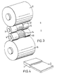
- the product to be manufactured by rolling is illustrated in Figure 4. Essentially it comprises a sheet of titanium alloy having a thickened end portion 1 and an integral thinner body portion 2. Typically the end portion 1 would have a thickness of 30mm whereas the thickness of the body portion 2 would be 7mm. The whole rolled member would be 500mm wide and the total length of the portions 1 and 2 would be 1000mm.
- the product illustrated in Figure 4 is manufactured from a plate having a starting thickness of the thickness of portion 1, a width of 500mm and a length of approximately 400mm.
- the product is manufactured by rolling in the mill illustrated in Figures 1 to 3.
- the rolling mill comprises a pair of work rolls 3, 4 supported on journals 5, 6.
- the journals are mounted in frames 7, 8 in a conventional manner.
- Backing rolls 9, 10 support the work rolls 3, 4 respectively.
- the backing rolls are mounted by means of journals 11, 12 in the frame 7, 8 as is conventional.
- Each of the work rolls 3, 4 is provided with a pocket 13, 14 extending partly around its circumference and the pockets 13 and 14 are matched so that during rotation of the work rolls 3, 4 they oppose one another as is illustrated in Figure 1.
- the plate is passed along a roller table 15 into the nip of the work rolls 3, 4.
- the end of the plate is positioned against a stop 16 as shown in Figure 1. It can be seen that in the arrangement illustrated in Figure 1 the plate 17 is free to move between the roll gap to contact the stop 16.
- the cam surfaces 20, 21 come into contact with the plate 17 and roll the plate to reduce it in thickness.
- the depth of the recesses 13, 14 is so arranged that even when the portion 2 is reduced to its smallest extent the end portion 1 is not reduced in thickness at all.
- the manufacturing method illustrated in Figures 1 to 3 produces a stepped plate product which is illustrated in Figure 4.
- the thickness of the portion 2 can be controlled to very narrow tolerances.
- the surface of the portion 2 is very uniform and free of defects, such as surface cracks and pits, which means that the surface can be readily fabricated to final dimensions by chemical milling. In the absence of such a clean surface, prior machining or surface conditioning of the portion 2 would be necessary to make it acceptable for chemical milling.
- FIG. 6A shows the plate 100 located between the work rolls 101, 102.
- the work rolls are just starting to nip the plate, having started the rolling process.
- the plate will be reduced in thickness over the portion beyond the pockets 103, 104 to attain the shape illustrated in Figure 6B.
- the work rolls are then slightly moved towards each other and the workpiece is inserted for a further revolution of the rolls. It can be seen that the rolling surfaces 105, 106 operate only on the surfaces 107, 108 of the workpiece 100, leaving the end portion 109 unrolled.
- Figure 7 shows the work rolls in their separated position when the workpiece is inserted. It can be seen that the end portion 111 of the workpiece can project through the work rolls to any desired extent. The portions 105, 106 of the work rolls are so arranged as to be a distance apart greater than the thickness of the end portion 111. The end portion 111 then projects through the gap formed by the pockets 103, 104.
- Figure 7 shows the shoulders 112, 113 of the radial recesses in which the pockets 103, 104 are located. The reason for the recess is given in detail below.
- the hump 30 increases in thickness relative to the.reducing thickness of the plate so that a non-uniform product is eventually formed. For this reason, for the tightest tolerances it is preferred that the pockets 13, 14 or 103, 104 be provided within complete circumferential recesses.
- the work rolls 3, 4 be heated during the rolling operation and prior to the rolling operation.
- the reason for this is that by preheating the work rolls they can attain a substantially uniform elevated temperature of approximately 100 to 200°C.
- Such a preheating obviates the formation of plate in the form illustrated in Figure 5B. From Figure 5B it can be seen that the thickness 31 of the portion 2 is less than the thickness 32 of the portion 2. It has been found that if cold work rolls are used the portion of the circumference of the work rolls remote from the recess is only contacted with hot metal as the rolling process proceeds and the portion 2 increases in length.
- the portion of the rolls in the region 20, 21 always sees hot metal whereas the portion remote from the regions 20, 21 along the circumference see hot metal only after a series of passes have been completed.
- the work rolls suffer from differential thermal radial expansion and the thickness of the portion 2 correspondingly varies along the length of the portion 2.
- the form of product illustrated in Figure 5C could be manufactured. It can be seen from this that the product has a substantially constant thickness over the region 33 but is tapered over the region 34. This tapered portion can be manufactured by suitable machining of the circumferential recess or pocket 22, 23.
- L-shaped plates may be manufactured as illustrated in Figure 5D.
- the end portion 1 has a substantially flat underside 35 and has a thinned upper face 36 which has a portion of constant thickness 37 and a tapered portion 38. If required the thickness of the reduced portion may be varied in thickness in a controlled manner over its entire length, for example to produce a tapered portion 2.
- the length of the portion 1 of the stepped plate can be any length as required.
- the portion 1 could be several metres long and simply be supported by a table, such as table 39, with rolling only occurring over a restricted length portion to produce a thin portion 2 of the stepped plate.
- a table such as table 39
- Such a unit may be useful in the manufacture of spars for aircraft wing production.
- Titanium and titanium alloys such as the alloy titanium plus 6wt% aluminium 4wt% vanadium, are extremely temperature-sensitive in regard to the pressure required for deformation versus temperature. As the temperature of the product falls the resistance to deformation of the metal increases rapidly.
- the apparatus and technique of the present invention enables titanium product to be rolled rapidly and this rapid rolling enables a profiled product to be manufactured which has a high surface integrity, being substantially free of cracking, pits and other surface defects. It will be appreciated, however, that other metals apart from titanium and titanium alloys could be processed by the route illustrated and described.
Landscapes
- Life Sciences & Earth Sciences (AREA)
- Agronomy & Crop Science (AREA)
- Engineering & Computer Science (AREA)
- Mechanical Engineering (AREA)
- Metal Rolling (AREA)
- Reduction Rolling/Reduction Stand/Operation Of Reduction Machine (AREA)
Claims (9)
Applications Claiming Priority (2)
| Application Number | Priority Date | Filing Date | Title |
|---|---|---|---|
| GB8408618 | 1984-04-04 | ||
| GB8408618 | 1984-04-04 |
Publications (2)
| Publication Number | Publication Date |
|---|---|
| EP0159818A1 EP0159818A1 (fr) | 1985-10-30 |
| EP0159818B1 true EP0159818B1 (fr) | 1988-10-26 |
Family
ID=10559134
Family Applications (1)
| Application Number | Title | Priority Date | Filing Date |
|---|---|---|---|
| EP85302018A Expired EP0159818B1 (fr) | 1984-04-04 | 1985-03-22 | Procédé et appareil pour la fabrication de produits métalliques |
Country Status (5)
| Country | Link |
|---|---|
| US (1) | US5070718A (fr) |
| EP (1) | EP0159818B1 (fr) |
| JP (1) | JPH074606B2 (fr) |
| CA (1) | CA1284039C (fr) |
| DE (1) | DE3565786D1 (fr) |
Families Citing this family (6)
| Publication number | Priority date | Publication date | Assignee | Title |
|---|---|---|---|---|
| US5528818A (en) * | 1992-07-10 | 1996-06-25 | Warneke; Horst | Assembly line for producing a steel coffer from sheet metal plate |
| DE19653543A1 (de) * | 1996-12-20 | 1998-06-25 | Audi Ag | Verfahren zum Herstellen eines Blechformteiles durch Tiefziehen |
| GB2377402B (en) * | 2001-07-12 | 2004-05-12 | Agilent Technologies Inc | Improved diebond strip |
| RU2393935C1 (ru) * | 2009-04-06 | 2010-07-10 | Борис Зельманович БОГУСЛАВСКИЙ | Способ штамповки с обкаткой и устройство для его осуществления |
| CN102397875B (zh) * | 2010-09-16 | 2014-01-01 | 鞍钢股份有限公司 | 一种纵向变厚度钢板的生产方法 |
| KR102348556B1 (ko) * | 2018-11-27 | 2022-01-06 | 주식회사 포스코 | 롤 포징 장치 |
Citations (1)
| Publication number | Priority date | Publication date | Assignee | Title |
|---|---|---|---|---|
| US1123460A (en) * | 1914-05-25 | 1915-01-05 | Henry K Adams | Apparatus for making rolled stay-bolts. |
Family Cites Families (15)
| Publication number | Priority date | Publication date | Assignee | Title |
|---|---|---|---|---|
| US156928A (en) * | 1874-11-17 | Improvement in machines for rolling blanks for nut-bars | ||
| US755433A (en) * | 1903-09-21 | 1904-03-22 | James H Baker | Forging apparatus. |
| US1568050A (en) * | 1921-11-22 | 1926-01-05 | Budd Wheel Co | Mill and method for rolling tapered disks |
| US1772538A (en) * | 1927-06-04 | 1930-08-12 | William H Donner | Method and apparatus for die rolling |
| US2736948A (en) * | 1950-07-03 | 1956-03-06 | Utica Drop Forge & Tool Corp | Forging apparatus |
| US2972181A (en) * | 1952-07-11 | 1961-02-21 | Power Jets Res & Dev Ltd | Process for making turbine blades |
| DE1024777B (de) * | 1952-12-20 | 1958-02-20 | Karlsruhe Augsburg Iweka | Verfahren zur Herstellung von Vollschaufeln aus hochwarmfesten Staehlen oder Legierungen fuer Turbinen und Kompressoren |
| US2958933A (en) * | 1955-07-22 | 1960-11-08 | Curtiss Wright Corp | Method for fabricating hollow blades |
| US3834207A (en) * | 1972-08-30 | 1974-09-10 | Anaconda American Brass Co | Method and apparatus for forming an accurately dimensioned metal strip having varying thickness |
| JPS5343864Y2 (fr) * | 1975-02-19 | 1978-10-21 | ||
| JPS5226223A (en) * | 1975-08-22 | 1977-02-26 | Fuji Photo Film Co Ltd | Photographic image formation method |
| JPS5487667A (en) * | 1977-12-23 | 1979-07-12 | Horikiri Spring Mfg | Method of forming taper leaf |
| JPS5933052B2 (ja) * | 1978-08-09 | 1984-08-13 | 愛知製鋼株式会社 | 板状材のテ−パ圧延装置 |
| US4316377A (en) * | 1979-11-23 | 1982-02-23 | Grotnes Metalforming Systems, Inc. | Roll forging machine |
| US4483168A (en) * | 1982-08-31 | 1984-11-20 | Sherman Alden O | Forming apparatus |
-
1985
- 1985-03-22 EP EP85302018A patent/EP0159818B1/fr not_active Expired
- 1985-03-22 DE DE8585302018T patent/DE3565786D1/de not_active Expired
- 1985-04-03 CA CA000478223A patent/CA1284039C/fr not_active Expired - Fee Related
- 1985-04-04 JP JP60071865A patent/JPH074606B2/ja not_active Expired - Lifetime
-
1988
- 1988-07-11 US US07/217,032 patent/US5070718A/en not_active Expired - Lifetime
Patent Citations (1)
| Publication number | Priority date | Publication date | Assignee | Title |
|---|---|---|---|---|
| US1123460A (en) * | 1914-05-25 | 1915-01-05 | Henry K Adams | Apparatus for making rolled stay-bolts. |
Also Published As
| Publication number | Publication date |
|---|---|
| US5070718A (en) | 1991-12-10 |
| EP0159818A1 (fr) | 1985-10-30 |
| JPS60231506A (ja) | 1985-11-18 |
| JPH074606B2 (ja) | 1995-01-25 |
| CA1284039C (fr) | 1991-05-14 |
| DE3565786D1 (en) | 1988-12-01 |
Similar Documents
| Publication | Publication Date | Title |
|---|---|---|
| US4162758A (en) | Method for producing clad steel pipes | |
| EP1751324B1 (fr) | Cible de pulverisation et procede pour former cette cible de pulverisation par forgeage axial rotatif | |
| EP0372999B1 (fr) | Procédé de fabrication d'un tube métallique plaqué | |
| CN110883093B (zh) | 铝合金不锈钢复合板异步冷轧成形工艺 | |
| US5042281A (en) | Isothermal sheet rolling mill | |
| EP3402619B1 (fr) | Procédés de fabrication de produits forgés et autres produits façonnés | |
| US5347837A (en) | Method of rolling using bendable sleeved roll | |
| EP2048260A1 (fr) | Procédé de fabrication d'un blanc en feuille à partir d'un alliage de titane | |
| EP1234623B1 (fr) | Procédé de fabrication de tôles comprenant des microstructures | |
| EP0159818B1 (fr) | Procédé et appareil pour la fabrication de produits métalliques | |
| US5572897A (en) | Method of obtaining hollow forgings by radial forging of solid blanks | |
| Kudo | Towards net-shape forming | |
| AU690717B2 (en) | Rolling mill for producing angle steel from hoop steel and method for rolling angle steel using the rolling mill | |
| FI3141335T4 (fi) | Menetelmä teräksestä valmistetun ydinosan sisältävän komponentin valmistamiseksi | |
| EP0597169B1 (fr) | Procédé pour lustrer les surfaces des tÔles et procédé pour laminer à froid des matériaux métalliques | |
| DE69612248T2 (de) | Verfahren zum Walzen von Hochgenauigkeitzahnrädern | |
| EP2281641A1 (fr) | Procédé de fabrication d'un tube sans soudure | |
| KR960010237B1 (ko) | 엔드리스 열간압연방법 | |
| RU2381083C1 (ru) | Способ изготовления лопаточных заготовок | |
| EP0132136B1 (fr) | Procédé et dispositif pour laminer les côtés d'acier en barres plates | |
| US2446892A (en) | Method of shaping bimetallic articles | |
| RU2553759C1 (ru) | Способ изготовления металлической защитной накладки | |
| CN115463990A (zh) | 一种航天工程用高质化微米级ta2箔材的制备方法 | |
| RU2234385C1 (ru) | Способ изготовления прокаткой стального слоистого материала | |
| SU732041A1 (ru) | Способ получени проката из труднодеформируемых и тугоплавких металлов и сплавов |
Legal Events
| Date | Code | Title | Description |
|---|---|---|---|
| PUAI | Public reference made under article 153(3) epc to a published international application that has entered the european phase |
Free format text: ORIGINAL CODE: 0009012 |
|
| AK | Designated contracting states |
Designated state(s): DE FR GB IT |
|
| 17P | Request for examination filed |
Effective date: 19860423 |
|
| 17Q | First examination report despatched |
Effective date: 19870708 |
|
| ITF | It: translation for a ep patent filed | ||
| GRAA | (expected) grant |
Free format text: ORIGINAL CODE: 0009210 |
|
| AK | Designated contracting states |
Kind code of ref document: B1 Designated state(s): DE FR GB IT |
|
| REF | Corresponds to: |
Ref document number: 3565786 Country of ref document: DE Date of ref document: 19881201 |
|
| ET | Fr: translation filed | ||
| PLBE | No opposition filed within time limit |
Free format text: ORIGINAL CODE: 0009261 |
|
| STAA | Information on the status of an ep patent application or granted ep patent |
Free format text: STATUS: NO OPPOSITION FILED WITHIN TIME LIMIT |
|
| 26N | No opposition filed | ||
| ITTA | It: last paid annual fee | ||
| REG | Reference to a national code |
Ref country code: FR Ref legal event code: CD |
|
| REG | Reference to a national code |
Ref country code: GB Ref legal event code: IF02 |
|
| PGFP | Annual fee paid to national office [announced via postgrant information from national office to epo] |
Ref country code: GB Payment date: 20040317 Year of fee payment: 20 |
|
| PGFP | Annual fee paid to national office [announced via postgrant information from national office to epo] |
Ref country code: FR Payment date: 20040318 Year of fee payment: 20 |
|
| PGFP | Annual fee paid to national office [announced via postgrant information from national office to epo] |
Ref country code: DE Payment date: 20040430 Year of fee payment: 20 |
|
| PG25 | Lapsed in a contracting state [announced via postgrant information from national office to epo] |
Ref country code: GB Free format text: LAPSE BECAUSE OF EXPIRATION OF PROTECTION Effective date: 20050321 |
|
| REG | Reference to a national code |
Ref country code: GB Ref legal event code: PE20 |