EP0159888A2 - Vollreifen - Google Patents
Vollreifen Download PDFInfo
- Publication number
- EP0159888A2 EP0159888A2 EP85302610A EP85302610A EP0159888A2 EP 0159888 A2 EP0159888 A2 EP 0159888A2 EP 85302610 A EP85302610 A EP 85302610A EP 85302610 A EP85302610 A EP 85302610A EP 0159888 A2 EP0159888 A2 EP 0159888A2
- Authority
- EP
- European Patent Office
- Prior art keywords
- tire
- members
- rib
- web
- web member
- Prior art date
- Legal status (The legal status is an assumption and is not a legal conclusion. Google has not performed a legal analysis and makes no representation as to the accuracy of the status listed.)
- Granted
Links
Images


Classifications
-
- B—PERFORMING OPERATIONS; TRANSPORTING
- B60—VEHICLES IN GENERAL
- B60C—VEHICLE TYRES; TYRE INFLATION; TYRE CHANGING; CONNECTING VALVES TO INFLATABLE ELASTIC BODIES IN GENERAL; DEVICES OR ARRANGEMENTS RELATED TO TYRES
- B60C7/00—Non-inflatable or solid tyres
- B60C7/24—Non-inflatable or solid tyres characterised by means for securing tyres on rim or wheel body
- B60C7/28—Non-inflatable or solid tyres characterised by means for securing tyres on rim or wheel body using straps or the like, e.g. vulcanised into the tyre
-
- B—PERFORMING OPERATIONS; TRANSPORTING
- B60—VEHICLES IN GENERAL
- B60C—VEHICLE TYRES; TYRE INFLATION; TYRE CHANGING; CONNECTING VALVES TO INFLATABLE ELASTIC BODIES IN GENERAL; DEVICES OR ARRANGEMENTS RELATED TO TYRES
- B60C15/00—Tyre beads, e.g. ply turn-up or overlap
- B60C15/02—Seating or securing beads on rims
- B60C15/0209—Supplementary means for securing the bead
- B60C15/0213—Supplementary means for securing the bead the bead being clamped by rings, cables, rim flanges or other parts of the rim
-
- B—PERFORMING OPERATIONS; TRANSPORTING
- B60—VEHICLES IN GENERAL
- B60C—VEHICLE TYRES; TYRE INFLATION; TYRE CHANGING; CONNECTING VALVES TO INFLATABLE ELASTIC BODIES IN GENERAL; DEVICES OR ARRANGEMENTS RELATED TO TYRES
- B60C15/00—Tyre beads, e.g. ply turn-up or overlap
- B60C15/02—Seating or securing beads on rims
- B60C15/0209—Supplementary means for securing the bead
- B60C15/0223—Supplementary means for securing the bead the bead being secured by clip-hook elements not forming part of the rim flange
-
- B—PERFORMING OPERATIONS; TRANSPORTING
- B60—VEHICLES IN GENERAL
- B60C—VEHICLE TYRES; TYRE INFLATION; TYRE CHANGING; CONNECTING VALVES TO INFLATABLE ELASTIC BODIES IN GENERAL; DEVICES OR ARRANGEMENTS RELATED TO TYRES
- B60C7/00—Non-inflatable or solid tyres
- B60C7/10—Non-inflatable or solid tyres characterised by means for increasing resiliency
- B60C7/12—Non-inflatable or solid tyres characterised by means for increasing resiliency using enclosed chambers, e.g. gas-filled
-
- B—PERFORMING OPERATIONS; TRANSPORTING
- B60—VEHICLES IN GENERAL
- B60C—VEHICLE TYRES; TYRE INFLATION; TYRE CHANGING; CONNECTING VALVES TO INFLATABLE ELASTIC BODIES IN GENERAL; DEVICES OR ARRANGEMENTS RELATED TO TYRES
- B60C7/00—Non-inflatable or solid tyres
- B60C7/24—Non-inflatable or solid tyres characterised by means for securing tyres on rim or wheel body
- B60C7/26—Non-inflatable or solid tyres characterised by means for securing tyres on rim or wheel body using bolts
Definitions
- a tire comprises an annular body of resilient elastomeric material having a generally cylindrical outer member at the outer periphery thereof, a generally cylindrical inner member spaced radially inward from and coaxial with said outer member, a plurality of axially extending, circumferentially spaced-apart rib members connected at their corresponding inner and outer ends to said inner and outer cylindrical members, said rib members being generally inclined at an angle of about 15° to 75° to radial planes which intersect them at their inner ends, and at least one web member having opposite side faces, said web member having its inner and outer peripheries connected respectively to said inner and outer cylindrical members and being connected on at least one of its side faces to at least one of said rib members to thereby form with said rib member a load-carrying and cushioning structure for said outer cylindrical member.
- the invention also extends to a tire and wheel rim assembly comprising a tire as aforesaid, a tread carried on the outer surface of said outer cylindrical member of said tire, a wheel rim member having a generally cylindrical outer surface, and means for mounting the inner surface of said inner cylindrical member of said tire on the outer surface of said wheel rim member in non-rotative engagement therewith.
- elastomer elastomers
- elastomeric material have reference to materials useful for making non-pneumatic tires and having the following characteristics: A Shore hardness of 60A to 75D, and a compression modulus (at 0.5 shape factor and 10% compression) of 6.9 x 10 3 to 344 x 10 3 kPa.
- the materials useful for making the non-pneumatic tires will have a Shore hardness of 70A to 60D, and the compression modulus will be from 8.2 x 10 3 to 172 x 10 3 kPa.
- a tire 10 is shown mounted on a wheel 12 for rotation about an axis 14.
- the tire 10 comprises an annular body 16 of resilient elastomeric material having an outer cylindrical member 18 at the outer periphery thereof on which a tread 20 may be mounted.
- the annular body 16 is also provided with an inner cylindrical member 22 at its inner periphery which is adhered to or otherwise fastened to an outer cylindrical surface 24 of wheel rim member 12.
- Inner cylindrical member 22 is of the same length as, coaxial to, and coextensive with outer cylindrical member 18.
- the outer cylinder member 18 is supported and cushioned by a plurality of circumferentially spaced-apart rib members 26, each of which includes a first axial portion 28 ( Figure 3) and a second axial portion 30, and by a web member 32, which in this embodiment of the invention is planar and is connected on one of its side faces 32a to the first portion 28 of rib members 26 and is connected on its other side face 32b to the second portion 30 of rib members 26.
- the planar web member 32 is positioned midway between the axial ends of the inner and outer cylindrical members 18 and 22. It is connected at its inner periphery 32c to the inner cylindrical member 22 and is connected at its outer periphery 32d to the outer cylindrical member 18.
- the various rib members 26 (Fiqure 2) are connected at their radially inner ends to the inner cylindrical member 22 and at their radially outer ends to the outer cylindrical member 18.
- the ribs 26 are preferably undercut where their ends connect to the inner and outer cylindrical members, as shown at 34, to enhance flexibility of the connection.
- first axial rib member portions 28 and the second axial rib member portions 30 are each inclined at the same angle to the radial planes R which intersect them at their radially inner ends but the angles of the first portions 28 are preferably oppositely directed with respect to the radial planes R from the angles of the second portions 30.
- first rib portion 28 proceeds upwardly from the section lines to connect with the outer cylindrical member 18, while the second rib portion 30 proceeds downwardly from the section lines to connect with the inner cylindrical member 22.
- the annular body portion 16 of the tire 10 preferably is formed with dimensions, dimensional relationships and angular relationships which fall within the broad, preferred and optimal ranges set forth in the following Table:
- the rib members 26 are constrained to deform primarily in compression by the influence of the web member 32, which may be cast as an integral part of the structure.
- the web member 32 tends to prevent the rib members 26 from deforming in bending, and the effect is to greatly increase structural stiffness.
- the tire 10 has advantages over prior art non-pneumatic tires in that it is much easier to mold and demold and can have a variable spring rate (by varying the inclination angle of the rib members 26) without requiring changes in the type of material from which it is made. This variation of spring rate with inclination angle of the rib members can be accomplished without greatly increasing compression strains in the rib member.
- undercuts 34 of appropriate radii at the junctions of the rib members 26 with the inner and outer cylindrical members 22 and 18.
- the undercuts 34 have a radius of about 0.32 cm to 1.27 cm on the acute angle junctions of the rib members 26 with the inner and outer cylindrical members 22 and 18, and they have a radius of about 0.64 cm to 2.54 cm on the obtuse angle junctions of the rib members 28 with the inner and outer cylindrical members 22 and 18.
- the annular body 16 may be adhered to the surface 24 of wheel rim 12 by being molded directly thereto in a liquid injection molding process, with the outer cylindrical surface 24 of the rim having been prepared in accordance with known processes to adheringly receive the . elastomeric material of the body 16.
- the wheel rim 12 is provided with radial flanges 36 and 38 which cooperate with the mold in forming the annular body 16 on the wheel rim surface 24.
- Alternative methods of mounting the tire body 16 on the wheel rim 12 are discussed hereinafter.
- the mold comprises an outer mold ring 42 which defines the outside diameter of the tire, and two mold plates 44, 46 which define the side edges of the annular body 16.
- Mold plate 44 is provided with a plurality of inserts 48 which are releasably fastened to the mold plate 44 by means of bolts 50.
- the inserts 48 are generally rhomboidally shaped and circumferentially spaced apart from one another so as to form the first axial portions 28 of rib members 26 between them during the molding operation.
- mold plate 46 is provided with a plurality of inserts 52 which are bolted thereto by bolts 54 with the inserts 52 being generally rhomboidally shaped and circumferentially spaced apart from one another to form the second axial portions 30 of rib members 26.
- the inside diameter of the annular body 16 is formed by the outer cylindrical surface 24 of the wheel rim 12.
- Suitable pairs of inner, annular flat washers 56 and outer, annular flat washers 58 are employed to space the mold plates 44 and 46 from the radial flanges of the wheel rim 12, in the case of the inner washers 56, and to space the mold plates 44 and 46 from the outer mold ring 42, in the case of the outer washers 58.
- the axial thickness of the washers 56 and 58 determine the axial thickness of the web member 32 and these may be varied depending on design conditions specified for the annular body 16.
- inserts 48 on mold plate 44 and the inserts 52 on mold plate 46 may be removed and replaced by corresponding inserts of different configuration when it is desired to change either the angular orientation or the thickness of the rib member portions 28 and 30, in accordance with desired design changes.
- An inlet spout 60 is provided for supplying liquid material to the mold from a source (not shown) during the mold filling operation, and an outlet valve 62 is provided to allow air to be removed from the mold during the filling operation.
- annular body 16 An alternative method of making the annular body 16 would employ, in place of the wheel rim 12, an inner mold ring (not shown) similar in configuration to the outer mold ring 42 but of lesser, appropriate diameter. After the annular body 16 has been molded and post-cured in this alternate method, the annular body 16 would be glued to a machined aluminium rim using a polyurethane adhesive.
- Example 1 provides details with respect to a non-pneumatic tire that was made in accordance with the preferred embodiment.
- the tire was made in a mold similar to that shown in Figures 4 and 5, but having an inner mold ring substituted in place of the wheel rim 12, as discussed above as an alternative method of making the annular body 16.
- the resulting mold was filled with a reaction mixture of (a) tolylenediisocyanate-poly(tetramethylene ether) glycol, (M.W. 2000), prepolymer having an NCO number of 5.45 and an amine equivalent of 767 and (b) a methylenedianiline-NaCl complex curative (50% by weight in dioctyl phthalate), the (a)/(b) weight ratio being 1/0.27.
- the mold was filled, it was placed for about one hour in an oven (set for 121°C) for the purpose of curinq the polyurethane. Subsequently, the mold was opened, the polyurethane annular body 16 was removed and the body was post-cured for about 16 hours at 70°C.
- a simple tire tread having a thickness of about 0.6 cm was then glued onto the outer cylindrical member 18 using a methyl 2-cyanoacrylate adhesive and the resulting tire was fitted and glued onto a steel rim member 12 using a polyurethane adhesive cured with an organic isocyanate curative.
- the resulting tire and wheel assembly was used to replace a conventional passenger car tire and wheel assembly.
- a car with the foregoing tire and wheel assembly was driven at speeds of up to 64 km/hr without deleteriously affecting control of the car and without damage to the non-pneumatic tire of this invention.
- the construction of the annular body 16 is essentially similar to that of the foregoing embodiment except that the angular orientation of the second axial portions 30a of rib members 26 has been reversed from the angular orientation of the second axial portions 30 of the rib members 26 in Figures 2 and 3, so that the second axial portions 30a of Figures 6 and 7 are in direct axial alignment with the first axial portions 28 of the rib members 26.
- This arrangement provides slightly different ride and handling characteristics from those of the embodiment shown in Figures 2 and 3.
- a mold similar to one half of the mold shown in Figure 4 may be used to make each of the annular half bodies 16a, 16b, the remaining half of the mold of Figure 4 would be replaced by a flat plate.
- the inner and outer rings of such a mold would be about half the axial length of the outer ring 42 of Fiqure 4, and the thicknesses of washers 56 and 58 would be appropriately selected to achieve the desired thickness of the web members 64 and 66 in this embodiment.
- FIG. 10 yet another embodiment of this invention has been shown.
- This embodiment is similar to the embodiment of Figures 8 and 9, except that the second axial portions 30 of the rib members are angularly oriented in the same direction as the first axial portions 28 of the rib members.
- the annular body 16 of this embodiment would be made in a mold similar to those already described but in this case two separate molds would be required, one for making each of the annular half bodies 16a and 16b so that the desired angular orientation of the rib portions 28 and 30 can be obtained.
- annular half bodies 16a and 16b similar to but slightly shorter in the axial dimension than those shown in the embodiment of Fiqures 8 and 9, are employed, together with a planar disc-shaped third web member 70.
- Annular half bodies 16a and 16b would be made in the same manner as described in connection with the embodiments of Fiqures 8 and 9, and an additional mould would be provided to make the web member 70.
- the three parts would then be adhesively joined together in a manner similar to that described in connection with the embodiment of Figures 8 and 9 to provide a cured annular body 16 having web members at either end thereof and in the central plane thereof.
- the construction of this embodiment would be employed when it is desired to have additional stiffening both at the ends of the annular body and in the central plane of the annular body.
- first axial rib member portions 28 and the second axial rib member portions 30 make equal but oppositely directed angles with their respective intersecting radial planes.
- FIG. 13 A still further embodiment of the invention is shown in Figure 13.
- a three-web-member version of the annular body 16 is employed in which the rib member portions 28 and 30 make angles with their respective intersecting radial planes which are both equal and similarly directed relative to such planes.
- the two annular half bodies 16a and 16b would be adhesively secured to the opposite side faces of the central web member 70 to provide an integral, composite body 16.
- Fiqures 15 and 16 yet another embodiment of this invention is shown in which extra provision is made for preventing slippage between the wheel rim and the inner cylindrical member 22 during acceleration and deceleration of the tire and wheel assembly.
- the inner surface of the inner cylindrical member 22 is provided with axially extending, circumferentially spaced depressions 74 and raised portions 76
- the outer surface 24 of the wheel rim 12 is provided with corresponding raised portions 78 and depressions 80 which interengage with the depressions and raised portions of the inner cylindrical member to prevent relative rotation therebetween.
- one end of the outer portion of wheel rim 12 is provided with a raised annular flange 36 thereon which abuts the inner cylindrical member 22, and the other end of the outer portion of wheel rim 12 is provided with a removable raised flange 38a which is bolted thereto by bolts 82.
- the removable flange 38 is unbolted and removed from the rim. Then, the various raised portions and depressions of the inner cylindrical member 22 and I" , outer surface 24 of the rim are coated with an adhesive and aligned, and the tire 10 is slid onto the rim 12. Thereafter, the removable flange 38a is bolted back onto the rim 12 and the adhesive bonding is allowed to cure before usage.
- the curing may be facilitated by placing the assembly in a suitable oven at an appropriate temperature for an appropriate length of time, depending upon the adhesive used.
- one conical web member comprises web member portions 86 and 88
- the other conical web member comprises the web member portions 84 and 90.
- Conical web members 84, 90 and 86, 88 each are in the form of a frustrum of a right circular cone having as its principal axis the rotational axis of the tire.
- the annular body 16 in this case is molded as two half bodies 16a and 16b which are then adhered together along their parting line 68 in a manner similar to that described in connection with the embodiment of Figure 9.
- Figure 18 shows an embodiment of this invention similar to that shown in Figure 17 but having two conical web members 92, 94 and 96, 98 which, rather than intersecting one another, have their radially inner ends terminating on the inner cylindrical member portions 22a and 22b respectively, at points adjacent to each other and to the parting line 68 of the annular half bodies 16a, 16b comprising the annular body 16.
- the web members 92, 94 and 96, 98 are substantially in abutting relationship with one another.
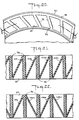
- Figure 22 shows a variation of the embodiment of Figures 20 and 21 in which web members 106, 106a, 106b, 106c, etc. form pairs of web members (e.g. pair 106 and 106a, pair 106a and 106b, pair 106b and 106c) wherein each web member of the pair extends from an opposite side of a common end of one rib member to the opposite end of a different next adjacent rib member 26.
- the web members form partial helices the projections of which intersect one another.
Landscapes
- Engineering & Computer Science (AREA)
- Mechanical Engineering (AREA)
- Tires In General (AREA)
Applications Claiming Priority (2)
| Application Number | Priority Date | Filing Date | Title |
|---|---|---|---|
| US60093284A | 1984-04-16 | 1984-04-16 | |
| US600932 | 1984-04-16 |
Related Child Applications (2)
| Application Number | Title | Priority Date | Filing Date |
|---|---|---|---|
| EP88111389A Division-Into EP0297628B1 (de) | 1984-04-16 | 1985-04-15 | Elastischer Radreifen |
| EP88111389A Division EP0297628B1 (de) | 1984-04-16 | 1985-04-15 | Elastischer Radreifen |
Publications (3)
| Publication Number | Publication Date |
|---|---|
| EP0159888A2 true EP0159888A2 (de) | 1985-10-30 |
| EP0159888A3 EP0159888A3 (en) | 1987-06-10 |
| EP0159888B1 EP0159888B1 (de) | 1991-03-13 |
Family
ID=24405655
Family Applications (2)
| Application Number | Title | Priority Date | Filing Date |
|---|---|---|---|
| EP85302610A Expired - Lifetime EP0159888B1 (de) | 1984-04-16 | 1985-04-15 | Vollreifen |
| EP88111389A Expired - Lifetime EP0297628B1 (de) | 1984-04-16 | 1985-04-15 | Elastischer Radreifen |
Family Applications After (1)
| Application Number | Title | Priority Date | Filing Date |
|---|---|---|---|
| EP88111389A Expired - Lifetime EP0297628B1 (de) | 1984-04-16 | 1985-04-15 | Elastischer Radreifen |
Country Status (8)
| Country | Link |
|---|---|
| EP (2) | EP0159888B1 (de) |
| JP (1) | JPS60236803A (de) |
| KR (1) | KR930007211B1 (de) |
| AU (1) | AU580294B2 (de) |
| BR (1) | BR8501777A (de) |
| CA (1) | CA1239854A (de) |
| DE (2) | DE3587076T2 (de) |
| ES (1) | ES295671Y (de) |
Cited By (26)
| Publication number | Priority date | Publication date | Assignee | Title |
|---|---|---|---|---|
| EP0245789A3 (en) * | 1986-05-13 | 1988-06-01 | The Uniroyal Goodrich Tire Company | Non-pneumatic tire with vibration reducing features |
| EP0334522A3 (en) * | 1988-03-23 | 1989-12-06 | Uniroyal Chemical Company, Inc. | Non-pneumatic tyre |
| EP0353006A3 (en) * | 1988-07-27 | 1990-05-16 | Sumitomo Rubber Industries, Ltd. | A non-pneumatic tyre |
| EP0391946A4 (en) * | 1987-12-15 | 1991-01-02 | Altrack Limited | Tyre construction |
| JPH04502006A (ja) * | 1988-11-23 | 1992-04-09 | メディカル リサーチ カウンスル | ヌクレオシド類似体 |
| US5343916A (en) * | 1991-02-27 | 1994-09-06 | The Goodyear Tire & Rubber Company | Non-pneumatic spare tire |
| US6564842B2 (en) | 1999-06-10 | 2003-05-20 | Michelin Recherche Et Technique S.A. | Lightened safety support for tire |
| US8056593B2 (en) | 2007-10-26 | 2011-11-15 | Chemtura Corporation | Non-pneumatic tire |
| US8061398B2 (en) | 2008-02-25 | 2011-11-22 | Chemtura Corporation | Non-pneumatic tire having angled tread groove wall |
| US20130319591A1 (en) * | 2010-06-18 | 2013-12-05 | Artic Investments S.A. | Non-pneumatic tire |
| US8783310B2 (en) | 2007-09-05 | 2014-07-22 | Bridgestone Corporation | Non-pneumatic tire |
| US20140311643A1 (en) * | 2013-04-18 | 2014-10-23 | Caterpillar Inc. | Molded tire having different tread material |
| US9108470B2 (en) | 2008-09-29 | 2015-08-18 | Polaris Industries Inc. | Run-flat device |
| US9139045B2 (en) | 2008-11-06 | 2015-09-22 | Chemtura Corporation | Multiple hardness non-pneumatic tire |
| CN105682937A (zh) * | 2013-10-22 | 2016-06-15 | 株式会社普利司通 | 非充气轮胎 |
| CN106379113A (zh) * | 2016-12-06 | 2017-02-08 | 安徽江淮汽车集团股份有限公司 | 无气轮胎及汽车 |
| US9573422B2 (en) | 2012-03-15 | 2017-02-21 | Polaris Industries Inc. | Non-pneumatic tire |
| US9662939B2 (en) | 2009-07-28 | 2017-05-30 | Bridgestone Americas Tire Operations, Llc | Tension-based non-pneumatic tire |
| CN107031289A (zh) * | 2015-10-26 | 2017-08-11 | 住友橡胶工业株式会社 | 实心轮胎 |
| PL423490A1 (pl) * | 2017-11-17 | 2019-05-20 | Korzekwa Anita Przed Produkcyjno Handlowe Anitex | Opona koła wózka dziecięcego |
| CN110001291A (zh) * | 2019-05-07 | 2019-07-12 | 蚌埠伊诺华轮胎有限公司 | 一种非充气式轮胎及其制造方法 |
| US10703140B2 (en) | 2015-01-27 | 2020-07-07 | Mtd Products Inc | Wheel assemblies with non-pneumatic tires |
| US10899169B2 (en) | 2015-01-27 | 2021-01-26 | Mtd Products Inc | Wheel assemblies with non-pneumatic tires |
| CN113195255A (zh) * | 2018-11-14 | 2021-07-30 | 普利司通美国轮胎运营有限责任公司 | 具有内轮辋部件和外轮辋部件的轮胎轮辋组件 |
| CN116330894A (zh) * | 2023-03-24 | 2023-06-27 | 大陆马牌轮胎(中国)有限公司 | 一种轮胎及车辆 |
| US11772424B2 (en) * | 2019-06-14 | 2023-10-03 | Ford Global Technologies, Llc | Serviceable non-pneumatic tire and wheel assemblies |
Families Citing this family (44)
| Publication number | Priority date | Publication date | Assignee | Title |
|---|---|---|---|---|
| AU618980B2 (en) * | 1987-12-15 | 1992-01-16 | Altrack Limited | Tyre construction |
| CA2011473C (en) * | 1989-05-22 | 1998-01-06 | Richard L. Palinkas | Trapezoidal non-pneumatic tire with supporting and cushioning members |
| FR2652310A1 (fr) * | 1989-09-28 | 1991-03-29 | Michelin & Cie | Bandage deformable non pneumatique. |
| US5223599A (en) * | 1992-04-10 | 1993-06-29 | Uniroyal Chemical Company, Inc. | Polyurethane elastomer and non-pneumatic tire fabricated therefrom |
| US6279630B1 (en) | 1998-12-23 | 2001-08-28 | Daimlerchrysler Ag | Non pneumatic tires |
| AUPQ087199A0 (en) * | 1999-06-09 | 1999-07-01 | Burns, Alan Robert | Tyre |
| US7650919B2 (en) | 1999-12-10 | 2010-01-26 | Michelin Recherche of Technique S.A. | Non-pneumatic tire having web spokes |
| US7418988B2 (en) | 1999-12-10 | 2008-09-02 | Michelin Recherche Et Technique S.A. | Non-pneumatic tire |
| CA2458002C (en) | 2001-08-24 | 2010-08-17 | Michelin Recherche Et Technique S.A. | Non-pneumatic tire |
| KR100783590B1 (ko) * | 2006-02-28 | 2007-12-11 | 김상효 | 완충 타이어 |
| JP3966895B1 (ja) | 2006-08-29 | 2007-08-29 | 横浜ゴム株式会社 | 非空気式タイヤ |
| KR100774495B1 (ko) * | 2006-11-15 | 2007-11-08 | 한국타이어 주식회사 | 비공기압 타이어 |
| US8104524B2 (en) | 2007-03-27 | 2012-01-31 | Resilient Technologies Llc | Tension-based non-pneumatic tire |
| US8109308B2 (en) | 2007-03-27 | 2012-02-07 | Resilient Technologies LLC. | Tension-based non-pneumatic tire |
| WO2009042460A2 (en) * | 2007-09-27 | 2009-04-02 | Societe De Technologie Michelin | Elastic shear band with helical coils |
| USD602852S1 (en) | 2007-10-26 | 2009-10-27 | Chemtura Corporation | Tire |
| USD602422S1 (en) | 2007-12-10 | 2009-10-20 | Chemtura Corporation | Tire |
| JP5377004B2 (ja) * | 2008-03-04 | 2013-12-25 | 株式会社ブリヂストン | 非空気入りタイヤ |
| JP5208570B2 (ja) * | 2008-04-30 | 2013-06-12 | 東洋ゴム工業株式会社 | 非空気圧タイヤ、リムホイール、及び車輪 |
| JP5225743B2 (ja) * | 2008-04-30 | 2013-07-03 | 東洋ゴム工業株式会社 | 非空気圧タイヤ |
| JP5441147B2 (ja) * | 2008-09-01 | 2014-03-12 | 福山ゴム工業株式会社 | 非空気式タイヤ |
| US8176957B2 (en) | 2009-07-20 | 2012-05-15 | Resilient Technologies, Llc. | Tension-based non-pneumatic tire |
| US8944125B2 (en) | 2009-07-20 | 2015-02-03 | Polaris Industries Inc. | Tension-based non-pneumatic tire |
| JP5774905B2 (ja) * | 2011-05-18 | 2015-09-09 | 東洋ゴム工業株式会社 | 非空気圧タイヤ |
| JP5972149B2 (ja) * | 2012-11-16 | 2016-08-17 | 東洋ゴム工業株式会社 | 非空気圧タイヤ |
| JP6076704B2 (ja) * | 2012-11-16 | 2017-02-08 | 東洋ゴム工業株式会社 | 非空気圧タイヤ |
| US9511631B2 (en) | 2012-12-26 | 2016-12-06 | Bridgestone Corporation | Non-pneumatic tire |
| JP6152285B2 (ja) | 2013-03-18 | 2017-06-21 | 東洋ゴム工業株式会社 | 搬送装置及び搬送方法 |
| JP5938366B2 (ja) * | 2013-05-15 | 2016-06-22 | 株式会社ブリヂストン | 非空気入りタイヤ |
| JP5894966B2 (ja) * | 2013-05-27 | 2016-03-30 | 株式会社ブリヂストン | 非空気入りタイヤ及び非空気入りタイヤの製造方法 |
| JP5851449B2 (ja) * | 2013-06-03 | 2016-02-03 | 株式会社ブリヂストン | 非空気入りタイヤ |
| JP5851450B2 (ja) * | 2013-06-06 | 2016-02-03 | 株式会社ブリヂストン | 非空気入りタイヤ |
| USD792332S1 (en) | 2015-06-03 | 2017-07-18 | Mtd Products Inc | Non-pneumatic tire |
| USD784917S1 (en) | 2015-06-03 | 2017-04-25 | Mtd Products Inc | Non-pneumatic tire |
| JP6630114B2 (ja) * | 2015-10-19 | 2020-01-15 | 株式会社ブリヂストン | 非空気入りタイヤ、金型および非空気入りタイヤの製造方法 |
| JP6604141B2 (ja) * | 2015-10-23 | 2019-11-13 | 住友ゴム工業株式会社 | エアレスタイヤ |
| CN106541784B (zh) * | 2016-12-06 | 2018-06-05 | 安徽江淮汽车集团股份有限公司 | 无气轮胎及汽车 |
| JP6754686B2 (ja) * | 2016-12-13 | 2020-09-16 | Toyo Tire株式会社 | 非空気圧タイヤ |
| TW201906747A (zh) * | 2017-07-06 | 2019-02-16 | 以色列商Ig硬紙板科技有限公司 | 輪胎 |
| JP7286961B2 (ja) * | 2018-12-20 | 2023-06-06 | 住友ゴム工業株式会社 | 車輪及び車輪の製造方法。 |
| JP7374229B2 (ja) * | 2019-06-20 | 2023-11-06 | ブリヂストン アメリカズ タイヤ オペレーションズ、 エルエルシー | モジュール式トレッドを有するタイヤ |
| CN110744974B (zh) * | 2019-09-27 | 2021-01-08 | 盐城恒远投资发展有限公司 | 新能源汽车 |
| US20210188003A1 (en) * | 2019-12-20 | 2021-06-24 | The Goodyear Tire & Rubber Company | Non-pneumatic tire and wheel assembly with integrated spoke structure |
| CN111319398A (zh) * | 2020-02-28 | 2020-06-23 | 季华实验室 | 支撑体、弹性支撑组件、非充气轮胎及其制造方法 |
Family Cites Families (12)
| Publication number | Priority date | Publication date | Assignee | Title |
|---|---|---|---|---|
| US2620844A (en) * | 1950-04-27 | 1952-12-09 | Lord Mfg Co | Cushioned tire |
| US3888545A (en) * | 1973-10-23 | 1975-06-10 | Arthur R Braun | Integral molded article having the appearance of a tire and an integral wheel-tire |
| US3907370A (en) * | 1974-05-01 | 1975-09-23 | Creatron Ind Inc | Plastic wheel construction for utility vehicles |
| DE2460051A1 (de) * | 1974-12-19 | 1976-07-01 | Bayer Ag | Einteilige pannensichere reifen |
| DE2460050A1 (de) * | 1974-12-19 | 1976-06-24 | Bayer Ag | Zweiteilige pannensichere reifen |
| PL112739B1 (en) * | 1976-05-04 | 1980-10-31 | Polyair Maschinenbau Gmbh | Cellular tyre |
| NL7903214A (nl) * | 1978-06-27 | 1980-01-02 | Gilmore Oscar Patrick | Van ribben voorziene band. |
| US4226273A (en) * | 1978-06-30 | 1980-10-07 | The Goodyear Tire & Rubber Company | Nonpneumatic tire and rim assembly |
| US4235270A (en) * | 1978-06-30 | 1980-11-25 | The Goodyear Tire & Rubber Company | Tire with supporting and cushioning walls |
| FR2498529A1 (fr) * | 1981-01-27 | 1982-07-30 | Surle Andre | Pneu polygonal |
| DE3148313C2 (de) * | 1981-12-07 | 1983-11-03 | Paul Vom Stein & Co, 5632 Wermelskirchen | Laufrolle für Apparate, Möbel od. dgl. |
| DE3230812A1 (de) * | 1982-08-19 | 1984-02-23 | Heinz 5000 Köln Komander | Bereifung fuer fahrzeuge, insbesondere fuer fahrraeder |
-
1985
- 1985-04-15 AU AU41226/85A patent/AU580294B2/en not_active Ceased
- 1985-04-15 KR KR1019850002508A patent/KR930007211B1/ko not_active Expired - Fee Related
- 1985-04-15 DE DE8888111389T patent/DE3587076T2/de not_active Expired - Lifetime
- 1985-04-15 CA CA000479113A patent/CA1239854A/en not_active Expired
- 1985-04-15 EP EP85302610A patent/EP0159888B1/de not_active Expired - Lifetime
- 1985-04-15 EP EP88111389A patent/EP0297628B1/de not_active Expired - Lifetime
- 1985-04-15 DE DE8585302610T patent/DE3582081D1/de not_active Expired - Lifetime
- 1985-04-15 JP JP60080045A patent/JPS60236803A/ja active Granted
- 1985-04-15 BR BR8501777A patent/BR8501777A/pt not_active IP Right Cessation
- 1985-04-16 ES ES1985295671U patent/ES295671Y/es not_active Expired
Cited By (37)
| Publication number | Priority date | Publication date | Assignee | Title |
|---|---|---|---|---|
| EP0245789A3 (en) * | 1986-05-13 | 1988-06-01 | The Uniroyal Goodrich Tire Company | Non-pneumatic tire with vibration reducing features |
| GR880100836A (el) * | 1987-12-15 | 1994-03-31 | Altrack Ltd | Κατασκευή ελαστικού. |
| EP0391946A4 (en) * | 1987-12-15 | 1991-01-02 | Altrack Limited | Tyre construction |
| US4934425A (en) * | 1988-03-23 | 1990-06-19 | Uniroyal Chemical Company, Inc. | Non-pneumatic tire |
| EP0334522A3 (en) * | 1988-03-23 | 1989-12-06 | Uniroyal Chemical Company, Inc. | Non-pneumatic tyre |
| EP0353006A3 (en) * | 1988-07-27 | 1990-05-16 | Sumitomo Rubber Industries, Ltd. | A non-pneumatic tyre |
| JPH04502006A (ja) * | 1988-11-23 | 1992-04-09 | メディカル リサーチ カウンスル | ヌクレオシド類似体 |
| US5343916A (en) * | 1991-02-27 | 1994-09-06 | The Goodyear Tire & Rubber Company | Non-pneumatic spare tire |
| US6564842B2 (en) | 1999-06-10 | 2003-05-20 | Michelin Recherche Et Technique S.A. | Lightened safety support for tire |
| US8783310B2 (en) | 2007-09-05 | 2014-07-22 | Bridgestone Corporation | Non-pneumatic tire |
| US8056593B2 (en) | 2007-10-26 | 2011-11-15 | Chemtura Corporation | Non-pneumatic tire |
| US8061398B2 (en) | 2008-02-25 | 2011-11-22 | Chemtura Corporation | Non-pneumatic tire having angled tread groove wall |
| US9108470B2 (en) | 2008-09-29 | 2015-08-18 | Polaris Industries Inc. | Run-flat device |
| US9139045B2 (en) | 2008-11-06 | 2015-09-22 | Chemtura Corporation | Multiple hardness non-pneumatic tire |
| US9662939B2 (en) | 2009-07-28 | 2017-05-30 | Bridgestone Americas Tire Operations, Llc | Tension-based non-pneumatic tire |
| US20130319591A1 (en) * | 2010-06-18 | 2013-12-05 | Artic Investments S.A. | Non-pneumatic tire |
| US10112442B2 (en) * | 2010-06-18 | 2018-10-30 | Artic Investments S.A. | Non-pneumatic tire |
| US9573422B2 (en) | 2012-03-15 | 2017-02-21 | Polaris Industries Inc. | Non-pneumatic tire |
| US20140311643A1 (en) * | 2013-04-18 | 2014-10-23 | Caterpillar Inc. | Molded tire having different tread material |
| US9180737B2 (en) * | 2013-04-18 | 2015-11-10 | Caterpillar Inc. | Molded tire having different tread material |
| US9616703B2 (en) | 2013-10-22 | 2017-04-11 | Bridgestone Corporation | Non-pneumatic tire |
| CN105682937A (zh) * | 2013-10-22 | 2016-06-15 | 株式会社普利司通 | 非充气轮胎 |
| CN105682937B (zh) * | 2013-10-22 | 2017-12-12 | 株式会社普利司通 | 非充气轮胎 |
| US10703140B2 (en) | 2015-01-27 | 2020-07-07 | Mtd Products Inc | Wheel assemblies with non-pneumatic tires |
| US10899169B2 (en) | 2015-01-27 | 2021-01-26 | Mtd Products Inc | Wheel assemblies with non-pneumatic tires |
| CN107031289A (zh) * | 2015-10-26 | 2017-08-11 | 住友橡胶工业株式会社 | 实心轮胎 |
| CN107031289B (zh) * | 2015-10-26 | 2021-07-06 | 住友橡胶工业株式会社 | 实心轮胎 |
| CN106379113A (zh) * | 2016-12-06 | 2017-02-08 | 安徽江淮汽车集团股份有限公司 | 无气轮胎及汽车 |
| CN106379113B (zh) * | 2016-12-06 | 2017-11-10 | 安徽江淮汽车集团股份有限公司 | 无气轮胎及汽车 |
| PL423490A1 (pl) * | 2017-11-17 | 2019-05-20 | Korzekwa Anita Przed Produkcyjno Handlowe Anitex | Opona koła wózka dziecięcego |
| CN113195255A (zh) * | 2018-11-14 | 2021-07-30 | 普利司通美国轮胎运营有限责任公司 | 具有内轮辋部件和外轮辋部件的轮胎轮辋组件 |
| US11724539B2 (en) | 2018-11-14 | 2023-08-15 | Bridgestone Americas Tire Operations, Llc | Tire rim assembly having inner and outer rim components |
| CN113195255B (zh) * | 2018-11-14 | 2024-01-19 | 普利司通美国轮胎运营有限责任公司 | 具有内轮辋部件和外轮辋部件的轮胎轮辋组件 |
| CN110001291A (zh) * | 2019-05-07 | 2019-07-12 | 蚌埠伊诺华轮胎有限公司 | 一种非充气式轮胎及其制造方法 |
| CN110001291B (zh) * | 2019-05-07 | 2024-01-12 | 蚌埠伊诺华轮胎有限公司 | 一种非充气式轮胎及其制造方法 |
| US11772424B2 (en) * | 2019-06-14 | 2023-10-03 | Ford Global Technologies, Llc | Serviceable non-pneumatic tire and wheel assemblies |
| CN116330894A (zh) * | 2023-03-24 | 2023-06-27 | 大陆马牌轮胎(中国)有限公司 | 一种轮胎及车辆 |
Also Published As
| Publication number | Publication date |
|---|---|
| AU580294B2 (en) | 1989-01-12 |
| CA1239854A (en) | 1988-08-02 |
| EP0159888B1 (de) | 1991-03-13 |
| ES295671Y (es) | 1988-12-01 |
| DE3587076D1 (de) | 1993-03-18 |
| EP0159888A3 (en) | 1987-06-10 |
| ES295671U (es) | 1988-04-16 |
| EP0297628A3 (en) | 1989-03-22 |
| KR930007211B1 (ko) | 1993-08-04 |
| JPH0359841B2 (de) | 1991-09-11 |
| EP0297628A2 (de) | 1989-01-04 |
| DE3587076T2 (de) | 1993-08-05 |
| DE3582081D1 (de) | 1991-04-18 |
| BR8501777A (pt) | 1985-12-10 |
| AU4122685A (en) | 1985-10-24 |
| EP0297628B1 (de) | 1993-02-03 |
| JPS60236803A (ja) | 1985-11-25 |
| KR850007749A (ko) | 1985-12-09 |
Similar Documents
| Publication | Publication Date | Title |
|---|---|---|
| EP0159888B1 (de) | Vollreifen | |
| EP0502353B1 (de) | Druckloser Reifen für Reserverad | |
| US9004127B2 (en) | Tension-based non-pneumatic tire | |
| FI87059B (fi) | Icke-pneumatiskt daeck. med baer- och fjaedringsorgan. | |
| US6681822B2 (en) | Non-pneumatic spare tire | |
| US5265659A (en) | Non-pneumatic tire with ride-enhancing insert | |
| US7143797B2 (en) | Airless tire | |
| EP0401564B1 (de) | Vollreifen mit Bienenwabenstruktur mit einer Einzel-Membran an einer Seite | |
| US20180361792A1 (en) | Tension-based non-pneumatic tire | |
| US9662939B2 (en) | Tension-based non-pneumatic tire | |
| US8944125B2 (en) | Tension-based non-pneumatic tire | |
| US4832098A (en) | Non-pneumatic tire with supporting and cushioning members | |
| EP0334522A2 (de) | Vollreifen | |
| US11014407B2 (en) | Tension-based non-pneumatic tire | |
| EP4105038B1 (de) | Baugruppe aus luftlosem reifen und felge | |
| US4936365A (en) | Anisotropic tire | |
| CA1136529A (en) | Cast tire and method of manufacture | |
| US3956448A (en) | Method of centrifugally casting a tire | |
| KR940010619B1 (ko) | 비공기압 타이어 | |
| WO1999054121A1 (en) | Multi-shot process of producing a non-pneumatic tire |
Legal Events
| Date | Code | Title | Description |
|---|---|---|---|
| PUAI | Public reference made under article 153(3) epc to a published international application that has entered the european phase |
Free format text: ORIGINAL CODE: 0009012 |
|
| AK | Designated contracting states |
Designated state(s): BE DE FR GB IT NL SE |
|
| PUAL | Search report despatched |
Free format text: ORIGINAL CODE: 0009013 |
|
| AK | Designated contracting states |
Kind code of ref document: A3 Designated state(s): BE DE FR GB IT NL SE |
|
| 17P | Request for examination filed |
Effective date: 19871202 |
|
| 17Q | First examination report despatched |
Effective date: 19880314 |
|
| RAP1 | Party data changed (applicant data changed or rights of an application transferred) |
Owner name: THE UNIROYAL GOODRICH TIRE COMPANY |
|
| ITF | It: translation for a ep patent filed | ||
| GRAA | (expected) grant |
Free format text: ORIGINAL CODE: 0009210 |
|
| AK | Designated contracting states |
Kind code of ref document: B1 Designated state(s): BE DE FR GB IT NL SE |
|
| REF | Corresponds to: |
Ref document number: 3582081 Country of ref document: DE Date of ref document: 19910418 |
|
| ET | Fr: translation filed | ||
| PLBE | No opposition filed within time limit |
Free format text: ORIGINAL CODE: 0009261 |
|
| STAA | Information on the status of an ep patent application or granted ep patent |
Free format text: STATUS: NO OPPOSITION FILED WITHIN TIME LIMIT |
|
| 26N | No opposition filed | ||
| NLS | Nl: assignments of ep-patents |
Owner name: UNIROYAL GOODRICH LICENSING SERVICES, INC. TE GREE |
|
| REG | Reference to a national code |
Ref country code: FR Ref legal event code: TP |
|
| EAL | Se: european patent in force in sweden |
Ref document number: 85302610.2 |
|
| ITPR | It: changes in ownership of a european patent |
Owner name: CESSIONE;UNIROYAL GOODRICH LICENSING SERVICES INC. |
|
| PGFP | Annual fee paid to national office [announced via postgrant information from national office to epo] |
Ref country code: SE Payment date: 19980319 Year of fee payment: 14 |
|
| PGFP | Annual fee paid to national office [announced via postgrant information from national office to epo] |
Ref country code: NL Payment date: 19980320 Year of fee payment: 14 |
|
| PGFP | Annual fee paid to national office [announced via postgrant information from national office to epo] |
Ref country code: BE Payment date: 19980417 Year of fee payment: 14 |
|
| PG25 | Lapsed in a contracting state [announced via postgrant information from national office to epo] |
Ref country code: SE Free format text: LAPSE BECAUSE OF NON-PAYMENT OF DUE FEES Effective date: 19990416 |
|
| PG25 | Lapsed in a contracting state [announced via postgrant information from national office to epo] |
Ref country code: BE Free format text: LAPSE BECAUSE OF NON-PAYMENT OF DUE FEES Effective date: 19990430 |
|
| BERE | Be: lapsed |
Owner name: UNIROYAL GOODRICH LICENSING SERVICES INC. Effective date: 19990430 |
|
| PG25 | Lapsed in a contracting state [announced via postgrant information from national office to epo] |
Ref country code: NL Free format text: LAPSE BECAUSE OF NON-PAYMENT OF DUE FEES Effective date: 19991101 |
|
| NLV4 | Nl: lapsed or anulled due to non-payment of the annual fee |
Effective date: 19991101 |
|
| EUG | Se: european patent has lapsed |
Ref document number: 85302610.2 |
|
| REG | Reference to a national code |
Ref country code: GB Ref legal event code: IF02 |
|
| PGFP | Annual fee paid to national office [announced via postgrant information from national office to epo] |
Ref country code: GB Payment date: 20040407 Year of fee payment: 20 |
|
| PGFP | Annual fee paid to national office [announced via postgrant information from national office to epo] |
Ref country code: FR Payment date: 20040420 Year of fee payment: 20 |
|
| PGFP | Annual fee paid to national office [announced via postgrant information from national office to epo] |
Ref country code: DE Payment date: 20040601 Year of fee payment: 20 |
|
| PG25 | Lapsed in a contracting state [announced via postgrant information from national office to epo] |
Ref country code: GB Free format text: LAPSE BECAUSE OF EXPIRATION OF PROTECTION Effective date: 20050414 |
|
| REG | Reference to a national code |
Ref country code: GB Ref legal event code: PE20 |