EP0159896A1 - Système de télécommande centralisé bi-directionnel à plusieurs fréquences - Google Patents
Système de télécommande centralisé bi-directionnel à plusieurs fréquences Download PDFInfo
- Publication number
- EP0159896A1 EP0159896A1 EP85302640A EP85302640A EP0159896A1 EP 0159896 A1 EP0159896 A1 EP 0159896A1 EP 85302640 A EP85302640 A EP 85302640A EP 85302640 A EP85302640 A EP 85302640A EP 0159896 A1 EP0159896 A1 EP 0159896A1
- Authority
- EP
- European Patent Office
- Prior art keywords
- frequency
- signal
- transmitter
- control system
- half cycle
- Prior art date
- Legal status (The legal status is an assumption and is not a legal conclusion. Google has not performed a legal analysis and makes no representation as to the accuracy of the status listed.)
- Granted
Links
Images





Classifications
-
- H—ELECTRICITY
- H02—GENERATION; CONVERSION OR DISTRIBUTION OF ELECTRIC POWER
- H02J—ELECTRIC POWER NETWORKS; CIRCUIT ARRANGEMENTS OR SYSTEMS FOR SUPPLYING OR DISTRIBUTING ELECTRIC POWER; SYSTEMS FOR STORING ELECTRIC ENERGY
- H02J13/00—Circuit arrangements for providing remote monitoring or remote control of equipment in a power distribution network
- H02J13/13—Circuit arrangements for providing remote monitoring or remote control of equipment in a power distribution network characterised by the transmission of data to equipment in the power network
- H02J13/1311—Circuit arrangements for providing remote monitoring or remote control of equipment in a power distribution network characterised by the transmission of data to equipment in the power network using the power network as support for the transmission
- H02J13/1313—Circuit arrangements for providing remote monitoring or remote control of equipment in a power distribution network characterised by the transmission of data to equipment in the power network using the power network as support for the transmission using pulsed signals
-
- H—ELECTRICITY
- H02—GENERATION; CONVERSION OR DISTRIBUTION OF ELECTRIC POWER
- H02J—ELECTRIC POWER NETWORKS; CIRCUIT ARRANGEMENTS OR SYSTEMS FOR SUPPLYING OR DISTRIBUTING ELECTRIC POWER; SYSTEMS FOR STORING ELECTRIC ENERGY
- H02J13/00—Circuit arrangements for providing remote monitoring or remote control of equipment in a power distribution network
- H02J13/18—Circuit arrangements for providing remote monitoring or remote control of equipment in a power distribution network characterised by the remotely-controlled equipment, e.g. converters or transformers
- H02J13/333—Circuit arrangements for providing remote monitoring or remote control of equipment in a power distribution network characterised by the remotely-controlled equipment, e.g. converters or transformers the equipment forming part of substations
-
- Y—GENERAL TAGGING OF NEW TECHNOLOGICAL DEVELOPMENTS; GENERAL TAGGING OF CROSS-SECTIONAL TECHNOLOGIES SPANNING OVER SEVERAL SECTIONS OF THE IPC; TECHNICAL SUBJECTS COVERED BY FORMER USPC CROSS-REFERENCE ART COLLECTIONS [XRACs] AND DIGESTS
- Y02—TECHNOLOGIES OR APPLICATIONS FOR MITIGATION OR ADAPTATION AGAINST CLIMATE CHANGE
- Y02E—REDUCTION OF GREENHOUSE GAS [GHG] EMISSIONS, RELATED TO ENERGY GENERATION, TRANSMISSION OR DISTRIBUTION
- Y02E60/00—Enabling technologies; Technologies with a potential or indirect contribution to GHG emissions mitigation
-
- Y—GENERAL TAGGING OF NEW TECHNOLOGICAL DEVELOPMENTS; GENERAL TAGGING OF CROSS-SECTIONAL TECHNOLOGIES SPANNING OVER SEVERAL SECTIONS OF THE IPC; TECHNICAL SUBJECTS COVERED BY FORMER USPC CROSS-REFERENCE ART COLLECTIONS [XRACs] AND DIGESTS
- Y04—INFORMATION OR COMMUNICATION TECHNOLOGIES HAVING AN IMPACT ON OTHER TECHNOLOGY AREAS
- Y04S—SYSTEMS INTEGRATING TECHNOLOGIES RELATED TO POWER NETWORK OPERATION, COMMUNICATION OR INFORMATION TECHNOLOGIES FOR IMPROVING THE ELECTRICAL POWER GENERATION, TRANSMISSION, DISTRIBUTION, MANAGEMENT OR USAGE, i.e. SMART GRIDS
- Y04S40/00—Systems for electrical power generation, transmission, distribution or end-user application management characterised by the use of communication or information technologies, or communication or information technology specific aspects supporting them
- Y04S40/12—Systems for electrical power generation, transmission, distribution or end-user application management characterised by the use of communication or information technologies, or communication or information technology specific aspects supporting them characterised by data transport means between the monitoring, controlling or managing units and monitored, controlled or operated electrical equipment
- Y04S40/121—Systems for electrical power generation, transmission, distribution or end-user application management characterised by the use of communication or information technologies, or communication or information technology specific aspects supporting them characterised by data transport means between the monitoring, controlling or managing units and monitored, controlled or operated electrical equipment using the power network as support for the transmission
Definitions
- This invention relates to improvements in a ripple control system, that is, a means and method for transmitting and receiving information through an alternating current power distribution system.
- Ripple control has been used in the past to transmit information from a power source to a load and thus afford remote control of that load, for example for control of water heaters, street lighting or the like.
- a squaring circuit was coupled to the signal output of each correlator and a summing circuit coupled to the squaring circuits, arranged so as to square and sum the D.C. voltage outputs of the correlators.
- SWD sequential wave form distortion
- conventional ripple control The differences between the sequential wave form distortion (SWD) control and conventional ripple control are that the signal was produced as a sequence of wave form distortions by applying a controlled oscillatory load to the power system, the frequency of the signal being locked to the supply frequency, and the synchronous correlation method of signal detection was used.
- the main object of this invention is to provide, improvements to the SWD control system of aforesaid Patent 531592.
- a synchronous filter wherein a pair of correlators were in quadrature and thereby were not phase sensitive.
- a code was utilised, employing closely spaced frequencies.
- improvements comprise a receiver wherein the receiver has a pair of synchronous filters driven 90° out of phase with each other, the outputs of which are squared and summed to form an output independent of phase, and further discrimination means comprising a microcomputer programmed for frequency checking of each synchronous filter output whereby frequency differences between the synchronous filter centre frequency and the incoming signal frequency are used to give complete rejection characteristics, thus producing a very narrow bandpass filter for the receiver detection system and enabling the use of a large number of closely spaced frequencies for the formation of signalling codes.
- This improvement results in the synchronous filter of the receivers having a much narrower band pass characteristic.
- This enhancement allows the full noise rejection advantage of synchronous correlators to be retained together with non-phase sensitivity.
- the filter is so selective that frequencies as closely spaced as 0.2 Hz can be used to form a multifrequency system of coding. This results in a very large number of usable frequencies between 200 and 1000 Hz and hence groups of unique frequencies can be assigned to each sub-station of a power system and thus overcomes all problems due to spillover of signal from one substation to the next via the high voltage supply system.
- the invention consists of a transmitter for transmitting a code and a receiver for receiving said code, said transmitter being coupled to the distribution system to superimpose a signal on the power frequency waveform as a sequence of waveform distortions, said transmitter embodying frequency control means to accurately generate closely spaced frequencies to enable the use of multifrequency codes, and improvements comprising an input detector circuit in said receiver having two synchronous filters driven ninety degrees out of phase with each other, means for squaring and ⁇ summing the synchronous filter outputs to form a non phase sensitive output, discrimination means comprising frequency checking means for the checking of frequency of each synchronous filter output whereby frequency differences between the synchronous filter centre frequency and the incoming signal frequency are used to give complete rejection characteristics to the filter thus producing a very narrow bandwidth filter.
- the invention further relates to improvements enhancing the operation of the oscillating load transmitter circuit.
- the level of oscillation in the transmitter circuit can be controlled. This allows the level of oscillation to be set electronically rather than by heavy current component design.
- Data pertaining to various other aspects of electrical power transmission can also be transmitted back to a central sub-station, reducing the need for an operator to travel.
- the transmitter and receiver costs for equipment in accordance with this invention are much lower than for conventional ripple control equipment.
- the extremely narrow-band pass filter of the receiver not only increases availability of a large number of signal frequencies but also gives much better rejection of noise signals than normal ripple control receivers and because of this a much lower - level of signal power can be used.
- the low signal power enables a small transmitter to be used and this contributes to the low cost.
- the two correlators ie, synchronous filters
- the transmitter may be of very simple design and consist of a capacitor in series with an inductor and switched to the power supply system with a pair of inverse parallel connected thyristors. Control of the thyristors is such that the circuit is made to oscillate in a discontinuous manner at a selectable signal frequency. Critical tuning of the capacitor and inductor is not required, since the resonant frequency thereof is always greater than the signal frequency. By using different signalling frequencies at each substation the problem of signal spillover from one sub-station to another is removed. It is, however, important that the signal itself should lie within close limits, and, although use can be made of crystal control means to control signal frequency, the control means referred to in said patent 531592 is equally as effective, and more cost effective than crystal control means.
- the system synthesises identical control frequencies in both the transmitter and receiver.
- This control frequency is synthesised by multiplying the power supply frequency by an integer using a phase locked loop multiplier circuit and then dividing by another integer.
- the control frequency is then used in the transmitter to control the oscillation of the inductive capacitive load and in the receiver to control the centre frequency of the synchronous filter. In this way a very precise signal frequency can be transmitted which can be detected by a very narrow band-pass filter.
- the input element of the receiver may consist of two synchronous filters each consisting of a pair of solid state (eg CMOS) change-over switches between a resistor and a capacitor.
- the change-over switches are driven by the control frequency but one filter is driven 90° out of phase with the other.
- the output frequency of these two filters will be equal to the difference between the signal frequency and the central frequency. Hence if the signal frequency is identical to the control frequency then the filter output frequency will be zero, that is a D.C. voltage.
- the total signal received is formed by combining the outputs from the two filters such that if P and Q are the separate outputs from each synchronous filter and S is the combined output then .
- the discrimination range of the overall filter is made narrower by checking the frequency of both P and Q by timing between their zero crossings.
- the signal is rejected if the frequency of both P and Q is higher than a predetermined difference frequency. It is this feature which achieves the very narrow-band pass frequency range, and in turn makes available a large number of signal frequencies to be usable in a CODE, even though the signal frequency may be below 1000 Hz. Availability of a large number of CODES makes it viable to signal "upstream" data from the consumer.
- the discontinuous oscillatory current in the large transmitter When transmitting from a power source, for example a sub-station, the discontinuous oscillatory current in the large transmitter will distort the power system voltage in proportion to the rate of change of current, since the source impedance is almost entirely inductive. Hence a signal of the desired frequency is generated on the power system voltage as a sequence of wave form distortions.
- a similar system is used for transmission in each direction. There is a difference, however, in that when transmitting "downstream” from a power source to a load the signal appears as a voltage superimposed on the power system voltage and when transmitting "upstream” from a load to a power source the signal appears as a current superimposed on the power system load current.
- the discontinuous oscillatory current of the small transmitter is isolated from the high voltage distribution lines at the sub-station by means of a current transformer.
- the output of the current transformer is passed through an impedance to convert it to a voltage then high pass filtered to remove most of the 50 Hz supply frequency. After amplification it is detected with the synchronous filter arrangement.
- a signal is produced on the distribution bus 21 (11kV or equivalent) of a sub-station which is then propagated via the 11 kV feeders 22 and 11 000/415 volt distribution transformers 23 to consumers.
- the signal appears at consumer premises between 240 volt active and neutral on all three phases simultaneously.
- the signal generating circuit is a switched LC load 24, 25 and results in a substantially constant load current I,.
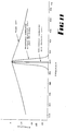
- the basic transmitter arrangement (in single phase form) is shown in FIG. and the load current relationship to the system voltage in FIG. 2.
- the transformer load consists of an air cored inductance 24 in series with a capacitor 25 and switched by means of inverse parallel connected thyristors 26.
- the load current does not flow continuously but has an "off" period 27 between each pulse.
- This off period is achieved by making the resonant frequency of the LC combination higher than 1.15 times the control frequency.
- the actual resonant frequency is not critical and hence it is not necessary to use expensive critically tuned components.
- the off period ensures the successful operation of the circuit and contributes to the simplicity of the design. Its presence causes the LC circuit to receive energy from the 50 Hz supply and hence oscillation can be maintained.
- the start of each current pulse is controlled by the firing of one or other of the thyristors by the control frequency (signalling frequency).
- the thyristors are commutated off as the current pulse goes to zero. This off period is varied with the arrangements which are described hereunder with reference to FIGS. 17, 18 and 19.
- this circuit can be enhanced by suitable control of the thyristor firing signals from the transmitter control unit 29.
- This control fires the thyristors in a pattern, the pattern frequency being the same as the power system frequency V but phase shifted from it by angle 'e' to V' as shown in FIG. 16.
- the thyristors are fired such that when V' is high oscillation current is continuous from the positive half cycle to the negative, and when V' is low oscillation current is continuous from the negative half cycle to the positive (FIG.17).
- the magnitude of oscillation current in the LC circuit can be varied over at least a 4:1 range. In this way the oscillation current can be set to the desired level.
- This arrangement is similar to the first arrangement (ie that used for low frequencies) except that the gap here lasts for a full cycle of the oscillation current and the resonant frequency of the LC combination is close to the control frequency.
- the control frequencies for firing the thryistors are always derived from the 50 Hz supply and hence are always locked to it. These frequencies are obtained by first multiplying the 50 Hz by an integer in a phase locked loop circuit 30 (FIG. 6) and then dividing by a different integer. In the system herein described a fixed multiplier of 4096 is used and the different frequencies are then formed by dividing by a factor K D . Hence the basic frequency equation is
- this arrangement is implemented on a o three phase basis, the current in each phase being 120 apart at the signalling frequency.
- the system arrangement is shown in FIG. 3.
- the minimum magnitude of signal voltage required is 0.16% of system voltage with the receivers set at a threshold level of 0.08%.
- a CODE consists of either 2 or 3 bits, each bit consisting of the transmission of a frequency for a set period of time.
- a CODE consists of a START bit and either one-or two CODE bits. The duration of each bit is critical. There are 5 different lengths of START bit each defining a different group of functions. There is only 1 length of CODE bit. The received duration of all bits must be between specified limits.
- the spacing between the START bit and the first CODE bit is also used to define different functions. Four different spacings are used.
- Addresses are formed by defining frequencies f , f and 1 2 f of the code. 3
- Functions are formed by defining the periods P and P .
- the 20 functions are arranged as follows:
- All bits are terminated by reversing the phase of the transmitted signal for 0.6 secs.
- the first START bit listed above consists of
- the total duration of each CODE bit is 3.5 secs ie 3.0 secs followed by 0.6 secs with phase reversed.
- each GROUP consisting of 8 frequencies formed by 8 adjacent values of K D .
- the frequencies closer than ⁇ 10 Hz of odd and ⁇ 5 Hz of even harmonics of 50 Hz are avoided as they occur naturally on the power system.
- a binary divider is used in the receivers for K D and the boundaries of each GROUP are determined when the 3 least significant bits of K D are 000 and 111.
- a 10 bit programmable divider is used for K D and controlled as follows: X, Y & Z are manually programmed into each receiver to set its address code.
- the selection of which GROUP of frequencies to use for any one sub-station will be determined by the power system characteristics.
- the main parameter which will affect selection will be the existence of 11 kV capacitor banks on the system, either as a large bank mounted in a sub-station, or smaller banks installed out along feeders. The existence of these banks will make it more economical to use the lower frequencies whereas if capacitor banks are not present, the higher frequencies will result in smaller transmitter components.
- Capacitor banks installed on the higher system voltage, ie 66 kV, will have negligible effect on signal generation. Since capacitor banks are not part of the invention, they are not illustrated herein.
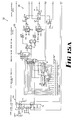
- the receiver 32 (FIG. 15) may be divided into 8 separate functional blocks as follows:
- the power supply only needs to provide a few milliamps. It can therefore be made very simple by using a capacitive divider, rectifier and regulator direct from the 240V AC supply (see FIG.5).
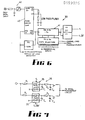
- the frequency synthesiser section is built up using a standard phase locked loop multiplier 40 followed by a programmable divider 41 to form the required filter frequency.
- the 50 Hz is multiplied by 16384 and then divided by an integer K D which is manually programmed in.. This results in a frequency four times the desired filter frequency and is subsequently divided to produce two control signals at the desired frequency but in quadrature (ie one displaced 90° from the other).
- K D integer which is manually programmed in.
- the selection of frequency Fc 1 , Fc 2 or Fc 3 is controlled by the data selectors D3 and D4 (FIG.6).
- a single stage RC filter and Schmitt trigger circuit 42 are used to condition the 50 Hz input signal from the supply to the phase locked loop (FIG. 6).
- the low pass filter from the phase comparator output on the phase locked loop to the voltage controlled oscillator (VCO) input needs to have a fairly long time constant for stability. For the same reason the VCO range selection resistors need to confine the VCO frequency to about ⁇ 10% of centre frequency.
- the synchronous filters 35 (or correlators) form the heart of the receiver circuit. These circuits extract the signal frequency from the 50 Hz supply and do so in a very selective manner.
- Each synchronous filter consists of a pair of solid state change-over switches in the middle of an RC filter (R1 C2), followed by a second stage pf RC filtering (R2 C2) for smoothing, as shown in FIG. 7.
- the switches will act as a synchronous rectifier and the rectified signal voltage will appear as a DC voltage on capacitor C2.
- the signal frequency is 90° out of phase with the correlator frequency, zero signal voltage will appear on C2.
- the correlator frequency is very slightly different from the transmitted frequency then, in effect, their phase relationship will change through 360° at a rate equal to the difference frequency, with the result that the voltage appearing on capacitor C2, will be low frequency AC.
- the total synchronous filter circuit gives ground referenced outputs at P & Q which are then sampled into the measurement circuit.
- the signals P and Q from each of the synchronous filters are measured alternately each second cycle of the 50 Hz, ie every 40 ms.
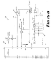
- a digital to analogue converter circuit is used controlled by a successive approximation routine in a microcomputer. rIG. 9 shows the circuit used.
- Microcomputer 44 is a Philips PCD3343, available from Philips, Eindhoven, Holland.
- the microcomputer 44 takes a digital measurement of each of the two synchronous filter outputs. The total signal S is then computed from S. In addition, when S is below threshold long running averages, using 256 samples, are also computed of P and Q and these values then used for zero correction. For most of the time no signal is present and hence if the signal is averaged with a long time constant it represents the residual signal.
- Such a residual can be present due to cross talk and leak current in the switches, bias current in the comparator and offset voltages in the comparator and operational amplifier. If the averaging time constant is made very long compared to signal duration the running average will not change appreciably during the receipt of a signal. The residual measurements for P and Q are then subtracted from P & Q to give corrected readings.
- the signal is tested for magnitude and the time it is above a set threshold is measured.
- the CODE bits have the shortest duration and they require that the signal is above threshold for at least 2.4 seconds but not more than 3.8 seconds.
- START bits with five different durations are used and they have the following limits.
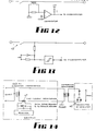
- the improved frequency discrimination is achieved by checking the frequency of each of the correlator outputs, ie P & Q. As explained before if the incoming signal frequency is slightly different from the synchronous filter frequency, then P and Q outputs will be at the difference frequency. This frequency can be checked by using the P and Q zero crossings to logically develop a rejection signal R as shown in FIG. 10. This logic is performed by a routine in the microcomputer and uses three flags, FT the threshold flag, FP the P flag and FQ the Q flag. If total signal S is below threshold all three flags are reset and rejection signal R is pulsed high. When S is above threshold flags FP and FQ are set respectively whenever P or Q perform a zero crossing.
- the microcomputer decides whether it is a START or a CODE bit according to its duration. All decoding of the signal is done by the microcomputer 44.
- the 50 Hz going in to the phase locked loop from the 16334 divider is compared in phase with the 50 Hz supply input. If the phase difference is greater than 300 ⁇ s the loop is considered to be OUT OF LOCK. Whenever an out of lock occurs the timers measuring signal duration are reset.
- a receiver When a receiver is used to control a storage hot water system, it is an advantage from a power system point of view to allow only one heating period during any prescribed ON time. For instance if an ON time is allowed between 10 pm and 7 am, then most heaters will attain full temperature say by 5 am and their thermostats will open. If a household then uses hot water at say 6 am, the thermostat will close and a second heating period will commence. This second heating period places load on the power system at a time when other loads are heavy (industry just starting up) and should therefore be avoided.
- the prescribed ON time cannot be made shorter because a small number of consumers will require the full time for their storage system to reach full temperature.
- a lockout routine is included which senses the condition that no load current is flowing when the contactor is closed (hence the thermostat must be open). Under these conditions the microcomputer operates the contactor to the OFF position.
- the contact sense and current sense circuits are described later.
- An over-ride timer routine is included to provide a fail-safe feature in the event of loss of communication with a sub-station. This can occur due to temporary feeder changes or a transmitter failure. This timer causes the output contactor to close 6.2 hours after the receipt of the last OFF command. If the contactor is required to remain off, a signal must be transmitted before the 6.2 hours expires in order to reset the timer. The only signal required to reset the timer is a START bit.
- a software routine is included in the microcomputer 44 which enables the switch ON of low usage consumers to be delayed. By timing each day the duration the water heater is energized and averaging this over a week a consumer's usage can be assessed. After an ON signal is sent, actual switch on can then be delayed in inverse proportion to normal usage. All these functions are embodied in the microcomputer software, the program of which forms no part of this invention. This allows the load of low usage consumers to be transferred to the early hours of the morning where there is a "trough" in the daily load curve.
- I When load current flows output I goes high on a 50 Hz basis. For no load current, I is low. The transition of I to the high state initiates an interrupt routine in the microcomputer. Current sense is used in the "lockout” and "delay” routines.
- the output contactor needs to be mechanically bi-stable and of the impulse type. That is, it should have only one coil which is energised for a short time (approximately 40 ms) to change the state of the contact.
- the relay should be as efficient as possible to minimise the power required to drive it.
- a single make contact is required having a current rating of at least 30 amperes AC resistive.
- upstream signalling uses current.
- a signal voltage of a very precise frequency is superimposed on the normal system voltage and this is detected by a synchronous filter in the receiver.
- upstream signalling a very small transmitter 46, but still of the same configuration as described above, is located at the consumer. The transmitter current is at a very precise frequency and may be detected at the sub-station by first turning it into a voltage with current transformer 47 and then using the synchronous filter to detect it.
- the basic arrangement is shown in FIG. 14.
- a multi-frequency scheme can be used for coding.
- variable data is required to be transmitted rather than control signals to specific addresses then a bank of fixed synchronous filters will be required, one for each frequency used.
- 10 frequencies are used to transmit decimal information
- 10 synchronous filters will be required and each frequency will represent a decimal number.
- simultaneous transmissions are possible on the same feeder. Simultaneous transmissions using the sane frequencies are also possible on different feeders as each feeder current is entirely separate.
- the thyristor control is such that firing of the thyristors is in a pattern (FIGS. 18 and 19), the pattern frequency being the same as the power system frequency but phase shifted from it, such that for one-half the period of the pattern, the transmitter load current is continuous from the positive half cycle to the negative half cycle and for the other half period transmitter load current is continuous from the negative half cycle to the positive half cycle, the basic firing frequency being the signal frequency required and the resonant frequency of the inductance capacitance combination being about 20% (between 5% and 50%) higher than the signal frequency (for the lower frequencies) thus causing discontinuous oscillation because of the short periods of zero load current.
- the capacitance inductance combination has about the same resonant frequency as the signal frequency and the firing pattern of the thyristors is such that oscillation is continuous except for one complete period of the oscillation following each transition of the pattern frequency.
- the capacitance inductance combination has about the same resonant frequency as the signal frequency and oscillation is only allowed on every alternate cycle.
- tie downstream signals are voltage signals and the upstream signals are current signals, this being necessary because of the inherent impedances of a power supply network.
- Reversals of phase in the transmitted signal which is referred to above is achieved merely by delaying the firing of the thyristors by 130°.
Landscapes
- Engineering & Computer Science (AREA)
- Power Engineering (AREA)
- Cable Transmission Systems, Equalization Of Radio And Reduction Of Echo (AREA)
Applications Claiming Priority (3)
| Application Number | Priority Date | Filing Date | Title |
|---|---|---|---|
| AU4614/84 | 1984-04-17 | ||
| AUPG461484 | 1984-04-17 | ||
| AU41056/85A AU579363B2 (en) | 1984-04-17 | 1985-04-11 | A Bi-Directional Multi-Frequency Ripple Control System |
Publications (2)
| Publication Number | Publication Date |
|---|---|
| EP0159896A1 true EP0159896A1 (fr) | 1985-10-30 |
| EP0159896B1 EP0159896B1 (fr) | 1987-11-19 |
Family
ID=25625443
Family Applications (1)
| Application Number | Title | Priority Date | Filing Date |
|---|---|---|---|
| EP85302640A Expired EP0159896B1 (fr) | 1984-04-17 | 1985-04-16 | Système de télécommande centralisé bi-directionnel à plusieurs fréquences |
Country Status (1)
| Country | Link |
|---|---|
| EP (1) | EP0159896B1 (fr) |
Cited By (3)
| Publication number | Priority date | Publication date | Assignee | Title |
|---|---|---|---|---|
| EP0340973A3 (fr) * | 1988-05-05 | 1990-12-27 | Gec Aerospace Limited | Systèmes de commande électriques |
| WO1996003792A1 (fr) * | 1994-07-28 | 1996-02-08 | Southpower Limited | Dispositif de regulation d'une charge energetique |
| US5903213A (en) * | 1994-07-28 | 1999-05-11 | Southpower Limited | Device for energy load control |
Citations (1)
| Publication number | Priority date | Publication date | Assignee | Title |
|---|---|---|---|---|
| GB2022890A (en) * | 1978-06-09 | 1979-12-19 | South Australia Electr Trust | Remote control |
-
1985
- 1985-04-16 EP EP85302640A patent/EP0159896B1/fr not_active Expired
Patent Citations (1)
| Publication number | Priority date | Publication date | Assignee | Title |
|---|---|---|---|---|
| GB2022890A (en) * | 1978-06-09 | 1979-12-19 | South Australia Electr Trust | Remote control |
Cited By (5)
| Publication number | Priority date | Publication date | Assignee | Title |
|---|---|---|---|---|
| EP0340973A3 (fr) * | 1988-05-05 | 1990-12-27 | Gec Aerospace Limited | Systèmes de commande électriques |
| WO1996003792A1 (fr) * | 1994-07-28 | 1996-02-08 | Southpower Limited | Dispositif de regulation d'une charge energetique |
| AU675192B2 (en) * | 1994-07-28 | 1997-01-23 | Cic Global Llc | Device for energy load control |
| US5903213A (en) * | 1994-07-28 | 1999-05-11 | Southpower Limited | Device for energy load control |
| CN1044185C (zh) * | 1994-07-28 | 1999-07-14 | 索思鲍尔有限公司 | 应用脉动信号的电路上的电能负载控制装置 |
Also Published As
| Publication number | Publication date |
|---|---|
| EP0159896B1 (fr) | 1987-11-19 |
Similar Documents
| Publication | Publication Date | Title |
|---|---|---|
| US4359644A (en) | Load shedding control means | |
| US4868539A (en) | Bi-directional multi-frequency ripple control system | |
| CA1087266A (fr) | Methode et appareil de communication par lignes de secteur | |
| US4106007A (en) | Method and apparatus for transmitting intelligence over a carrier wave | |
| CA1207037A (fr) | Demodulateur | |
| US4218655A (en) | Method and apparatus for transmitting intelligence over a carrier wave | |
| CA2429581C (fr) | Appareil d'envoi et de reception de donnees au moyen de transformateurs de distribution d'energie | |
| US4491785A (en) | Tracing electrical conductors by high-frequency loading and improved signal detection | |
| US4371867A (en) | Transmitting signals over alternating current power networks | |
| O'Neal | The residential power circuit as a communication medium | |
| US6411073B1 (en) | Method and device for locating a metal line | |
| WO2002021664A1 (fr) | Procede, systeme et dispositifs permettant la transmission de donnees dans un reseau electrique | |
| EP0159896B1 (fr) | Système de télécommande centralisé bi-directionnel à plusieurs fréquences | |
| EP0029447A1 (fr) | Commande en frequence pour des systemes a courant alternatif connectes en parallele. | |
| US3986121A (en) | Method for remote control through a power supply system and apparatus for carrying out the same | |
| JPS6195639A (ja) | データ伝送方法 | |
| US4310829A (en) | Transmitting device for communications equipment for generating a signal to be superimposed on an AC power supply network | |
| US5144280A (en) | Bi-directional multi-frequency ripple control system | |
| AU628154B2 (en) | Frequency shift keying modulation and demodulation for serial communication on a current loop | |
| US4510399A (en) | Demodulator circuit for parallel AC power systems | |
| AU617204B2 (en) | A bi-directional multi-frequency ripple control system | |
| US5208720A (en) | Electronic trip device with short delay function | |
| KR101187729B1 (ko) | 교류전류의 위상을 이용한 전력선 통신장치 | |
| SU1069054A1 (ru) | Устройство дл защитного отключени в сети с глухозаземленной нейтралью | |
| RU2025856C1 (ru) | Устройство для защиты от изменения напряжения |
Legal Events
| Date | Code | Title | Description |
|---|---|---|---|
| PUAI | Public reference made under article 153(3) epc to a published international application that has entered the european phase |
Free format text: ORIGINAL CODE: 0009012 |
|
| AK | Designated contracting states |
Designated state(s): CH DE GB LI NL |
|
| 17P | Request for examination filed |
Effective date: 19851206 |
|
| 17Q | First examination report despatched |
Effective date: 19860909 |
|
| GRAA | (expected) grant |
Free format text: ORIGINAL CODE: 0009210 |
|
| AK | Designated contracting states |
Kind code of ref document: B1 Designated state(s): CH DE GB LI NL |
|
| REF | Corresponds to: |
Ref document number: 3561036 Country of ref document: DE Date of ref document: 19871223 |
|
| PLBE | No opposition filed within time limit |
Free format text: ORIGINAL CODE: 0009261 |
|
| STAA | Information on the status of an ep patent application or granted ep patent |
Free format text: STATUS: NO OPPOSITION FILED WITHIN TIME LIMIT |
|
| 26N | No opposition filed | ||
| PGFP | Annual fee paid to national office [announced via postgrant information from national office to epo] |
Ref country code: GB Payment date: 19980421 Year of fee payment: 14 |
|
| PGFP | Annual fee paid to national office [announced via postgrant information from national office to epo] |
Ref country code: CH Payment date: 19980422 Year of fee payment: 14 |
|
| PGFP | Annual fee paid to national office [announced via postgrant information from national office to epo] |
Ref country code: NL Payment date: 19980430 Year of fee payment: 14 |
|
| PGFP | Annual fee paid to national office [announced via postgrant information from national office to epo] |
Ref country code: DE Payment date: 19980529 Year of fee payment: 14 |
|
| PG25 | Lapsed in a contracting state [announced via postgrant information from national office to epo] |
Ref country code: GB Free format text: LAPSE BECAUSE OF NON-PAYMENT OF DUE FEES Effective date: 19990416 |
|
| PG25 | Lapsed in a contracting state [announced via postgrant information from national office to epo] |
Ref country code: LI Free format text: LAPSE BECAUSE OF NON-PAYMENT OF DUE FEES Effective date: 19990430 Ref country code: CH Free format text: LAPSE BECAUSE OF NON-PAYMENT OF DUE FEES Effective date: 19990430 |
|
| PG25 | Lapsed in a contracting state [announced via postgrant information from national office to epo] |
Ref country code: NL Free format text: LAPSE BECAUSE OF NON-PAYMENT OF DUE FEES Effective date: 19991101 |
|
| GBPC | Gb: european patent ceased through non-payment of renewal fee |
Effective date: 19990416 |
|
| REG | Reference to a national code |
Ref country code: CH Ref legal event code: PL |
|
| NLV4 | Nl: lapsed or anulled due to non-payment of the annual fee |
Effective date: 19991101 |
|
| PG25 | Lapsed in a contracting state [announced via postgrant information from national office to epo] |
Ref country code: DE Free format text: LAPSE BECAUSE OF NON-PAYMENT OF DUE FEES Effective date: 20000201 |