EP0159909A2 - Charge d'un fluide chargé d'une phase dispersée - Google Patents
Charge d'un fluide chargé d'une phase dispersée Download PDFInfo
- Publication number
- EP0159909A2 EP0159909A2 EP85302675A EP85302675A EP0159909A2 EP 0159909 A2 EP0159909 A2 EP 0159909A2 EP 85302675 A EP85302675 A EP 85302675A EP 85302675 A EP85302675 A EP 85302675A EP 0159909 A2 EP0159909 A2 EP 0159909A2
- Authority
- EP
- European Patent Office
- Prior art keywords
- charge
- dispersed phase
- contaminant
- liquid
- fluid
- Prior art date
- Legal status (The legal status is an assumption and is not a legal conclusion. Google has not performed a legal analysis and makes no representation as to the accuracy of the status listed.)
- Granted
Links
Images

Classifications
-
- B—PERFORMING OPERATIONS; TRANSPORTING
- B03—SEPARATION OF SOLID MATERIALS USING LIQUIDS OR USING PNEUMATIC TABLES OR JIGS; MAGNETIC OR ELECTROSTATIC SEPARATION OF SOLID MATERIALS FROM SOLID MATERIALS OR FLUIDS; SEPARATION BY HIGH-VOLTAGE ELECTRIC FIELDS
- B03C—MAGNETIC OR ELECTROSTATIC SEPARATION OF SOLID MATERIALS FROM SOLID MATERIALS OR FLUIDS; SEPARATION BY HIGH-VOLTAGE ELECTRIC FIELDS
- B03C5/00—Separating dispersed particles from liquids by electrostatic effect
- B03C5/02—Separators
- B03C5/022—Non-uniform field separators
- B03C5/024—Non-uniform field separators using high-gradient differential dielectric separation, i.e. using a dielectric matrix polarised by an external field
-
- B—PERFORMING OPERATIONS; TRANSPORTING
- B01—PHYSICAL OR CHEMICAL PROCESSES OR APPARATUS IN GENERAL
- B01D—SEPARATION
- B01D17/00—Separation of liquids, not provided for elsewhere, e.g. by thermal diffusion
- B01D17/06—Separation of liquids from each other by electricity
-
- B—PERFORMING OPERATIONS; TRANSPORTING
- B01—PHYSICAL OR CHEMICAL PROCESSES OR APPARATUS IN GENERAL
- B01D—SEPARATION
- B01D35/00—Filtering devices having features not specifically covered by groups B01D24/00 - B01D33/00, or for applications not specifically covered by groups B01D24/00 - B01D33/00; Auxiliary devices for filtration; Filter housing constructions
- B01D35/06—Filters making use of electricity or magnetism
-
- B—PERFORMING OPERATIONS; TRANSPORTING
- B05—SPRAYING OR ATOMISING IN GENERAL; APPLYING FLUENT MATERIALS TO SURFACES, IN GENERAL
- B05B—SPRAYING APPARATUS; ATOMISING APPARATUS; NOZZLES
- B05B5/00—Electrostatic spraying apparatus; Spraying apparatus with means for charging the spray electrically; Apparatus for spraying liquids or other fluent materials by other electric means
- B05B5/08—Plant for applying liquids or other fluent materials to objects
Definitions
- the charge injector comprises essentially a chamber through which liquid can flow, a low-voltage electrode at one end of the chamber defining a discharge orifice, a pointed high-voltage, electrode arranged with its tip close to, and in axial alignment with, the discharge orifice and an earthed electrode outside the chamber downstream from the discharge orifice so as to complete the electrical circuit of the charge injector.
- Various applications of the charge injector are disclosed in U.S. patent 4,255,777 such as electrostatic coating or spraying or the atomisation of hydrocarbon fuel delivered to the combustion chamber of domestic and industrial oil burners.
- the charge introduction means comprise a charge injector and the charge injector can be similar to that disclosed in the aforesaid U.S. patent 4,255,777.
- the charge injector preferably comprises a high-potential electrode having a pointed end, a low-potential electrode arranged in the proximity of the.tip of the high-potential electrode, the low-potential electrode defining a discharge opening close to and in axial alignment with the tip of the high-potential electrode, and means for flowing a stream of the further fluid past the tip of the high-potential electrode and through the discharge opening in the low-potential electrode so that charge is injected from the high-potential electrode tip into the stream of further fluid.
- the next part in the process involves the conglomeration of the contaminants.
- the contaminants are present in the liquid mixture at number densities where the mean contaminant-contaminant separation is less than, and preferably significantly less (e.g., 1% or less) than, the internal dimensions of the separation vessel (e.g., its diameter, in the case of an upright cylindrical separation vessel) and assuming no internal collector surfaces within the separation region, agglomeration or coalescence of the contaminants will occur predominantly in the bulk of the liquid mixture to form large particles, droplets or bubbles, as the case may be and less contaminant will reach the separation vessel wall surfaces.
- “Mean inter-contaminant separation” denotes the arithmetic mean value before any migration of the contaminants following the introduction of free charge, starts to occur.
- the congregation, conglomeration and coalescence may continue until each contaminant either reaches the boundary of the liquid mixture or a collector surface, or increases in size until it becomes separated from the bulk of the liquid mixture by conventional methods such as centrifugation, settling, or mechanical filtering.
- this may conveniently entail settling (or flotation, depending upon the density of the contaminant phase relative to that of the liquid) of the re-entrained liquid contaminants, to form a distinct continuous contaminant phase, to enable separation of the two liquid phases.
- the microscopic liquid droplets merely congregate on the collector and/or wall surfaces.
- the separation vessel is provided with means responsive to the level of liquid in the primary conglomerating region for regulating the rate of supply of the contaminant-free li.quid so as to maintain the level substantially constant.
- the liquid level preferably just covers all the beads.
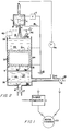
- a mixture consisting of a dispersed contaminant phase in a continuous background phase in this case a water-in-oil emulsion containing micron-sized water droplets, is delivered through line 42 into a mixing chamber 33 in upper section of an upright, preferably cylindrical, open topped separation reservoir or vessel 6.
- oil that is substantially free of water or other dispersed contaminant and is preferably identical to the oil in the water-in-oil emulsion is introduced into the inlet of charge injector 1 taking the form of a charge injector which injects free charge (net positive or negative) into the mixture.
- valves 17, 19 are set to define predetermined flow discharge rates for the clarified water and oil phases
- an optional level control arrangement can be used to keep the level of the oil mixture in section 33 substantially constant, this arrangement comprising a controller 40 which responds to the level detected by a level sensor 39 and controls the opening of a regulator 41 in the input line 42 so as to reduce any error between the output from level 'sensor 39 and an input signal representing the desired level.
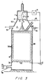
- separation apparatus that is specially suitable for separating small particles of solid contaminant from a liquid background phase, for example white mineral oil contaminated with carbon black particles.
Landscapes
- Chemical & Material Sciences (AREA)
- Chemical Kinetics & Catalysis (AREA)
- Physics & Mathematics (AREA)
- Thermal Sciences (AREA)
- Engineering & Computer Science (AREA)
- Water Supply & Treatment (AREA)
- Electrostatic Separation (AREA)
Applications Claiming Priority (2)
| Application Number | Priority Date | Filing Date | Title |
|---|---|---|---|
| US06/601,274 US4618432A (en) | 1984-04-17 | 1984-04-17 | Method and apparatus for charging a contaminant-laden liquid |
| US601274 | 1984-04-17 |
Publications (3)
| Publication Number | Publication Date |
|---|---|
| EP0159909A2 true EP0159909A2 (fr) | 1985-10-30 |
| EP0159909A3 EP0159909A3 (en) | 1986-02-12 |
| EP0159909B1 EP0159909B1 (fr) | 1990-03-28 |
Family
ID=24406878
Family Applications (1)
| Application Number | Title | Priority Date | Filing Date |
|---|---|---|---|
| EP85302675A Expired - Lifetime EP0159909B1 (fr) | 1984-04-17 | 1985-04-17 | Charge d'un fluide chargé d'une phase dispersée |
Country Status (5)
| Country | Link |
|---|---|
| US (1) | US4618432A (fr) |
| EP (1) | EP0159909B1 (fr) |
| JP (1) | JPS6133249A (fr) |
| CA (1) | CA1250545A (fr) |
| DE (1) | DE3576787D1 (fr) |
Families Citing this family (13)
| Publication number | Priority date | Publication date | Assignee | Title |
|---|---|---|---|---|
| US5093602A (en) * | 1989-11-17 | 1992-03-03 | Charged Injection Corporation | Methods and apparatus for dispersing a fluent material utilizing an electron beam |
| US5515681A (en) * | 1993-05-26 | 1996-05-14 | Simmonds Precision Engine Systems | Commonly housed electrostatic fuel atomizer and igniter apparatus for combustors |
| US5367869A (en) * | 1993-06-23 | 1994-11-29 | Simmonds Precision Engine Systems | Laser ignition methods and apparatus for combustors |
| DE19536604A1 (de) * | 1994-10-04 | 1996-04-11 | Simmonds Precision Engine Syst | Zündvorrichtung und Zündverfahren unter Verwendung elektrostatischer Düse und katalytischen Zünders |
| US5631802A (en) * | 1995-01-13 | 1997-05-20 | Clark Equipment Company | Control ring for input spray in electrostatic spray system |
| US5788827A (en) * | 1997-02-10 | 1998-08-04 | M.A.G. Systems, Inc. | Means and method for removing particulate matter from nonconductive liquids |
| WO2003028879A1 (fr) * | 2001-10-01 | 2003-04-10 | Isopur Fluid Technologies, Inc. | Electrodes de transfert de charges pour courant a faible debit |
| WO2003078571A2 (fr) * | 2002-02-14 | 2003-09-25 | Wen Sheree H | Dispositif anti-infectieux et d'elimination de toxines |
| US7931734B2 (en) * | 2007-08-29 | 2011-04-26 | Board Of Regents Of The Nevada System Of Higher Education, On Behalf Of The Desert Research Institute | Particle separation |
| US8396700B2 (en) * | 2008-09-02 | 2013-03-12 | Board Of Regents Of The Nevada System Of Higher Education, On Behalf Of The Desert Research Institute | Aggregate simulation |
| US20100224479A1 (en) * | 2009-02-02 | 2010-09-09 | The Board of Regents of the Nevada System of Higher Educ., on Behalf of the Desert Res. Inst. | Morphology engineering of aggregates |
| CN110668631A (zh) * | 2019-10-09 | 2020-01-10 | 恩宜瑞(江苏)环境发展有限公司 | 一种基于管式膜的高浓度含油废水破乳系统及方法 |
| WO2024030666A1 (fr) | 2022-08-05 | 2024-02-08 | FouRy, Inc. | Systèmes et procédés pour un atomiseur électrostatique de fluides modérément conducteurs |
Family Cites Families (7)
| Publication number | Priority date | Publication date | Assignee | Title |
|---|---|---|---|---|
| US2061197A (en) * | 1933-10-02 | 1936-11-17 | Petroleum Rectifying Co California | Method and apparatus for treating emulsions |
| US2054273A (en) * | 1933-12-26 | 1936-09-15 | Union Oil Co | Process and apparatus for dewaxing oil |
| US2072888A (en) * | 1934-03-26 | 1937-03-09 | Petroleum Rectifying Co | Method of and apparatus for protecting insulating bushings of a dehydrator |
| US4255777A (en) * | 1977-11-21 | 1981-03-10 | Exxon Research & Engineering Co. | Electrostatic atomizing device |
| DE2837356C2 (de) * | 1978-08-26 | 1986-04-30 | Institut fizičeskoj chimii Akademii Nauk SSSR, Moskau/Moskva | Verfahren zur Reinigung von Detergentzusatzstoffen für Schmieröle von mechanischen Beimengungen |
| US4194956A (en) * | 1978-12-22 | 1980-03-25 | The Procter & Gamble Company | Method for dewaxing high-resistivity oils |
| JPS57501565A (fr) * | 1980-10-24 | 1982-09-02 |
-
1984
- 1984-04-17 US US06/601,274 patent/US4618432A/en not_active Expired - Fee Related
-
1985
- 1985-04-17 EP EP85302675A patent/EP0159909B1/fr not_active Expired - Lifetime
- 1985-04-17 JP JP8211385A patent/JPS6133249A/ja active Pending
- 1985-04-17 DE DE8585302675T patent/DE3576787D1/de not_active Expired - Lifetime
- 1985-04-17 CA CA000479380A patent/CA1250545A/fr not_active Expired
Also Published As
| Publication number | Publication date |
|---|---|
| US4618432A (en) | 1986-10-21 |
| CA1250545A (fr) | 1989-02-28 |
| EP0159909A3 (en) | 1986-02-12 |
| EP0159909B1 (fr) | 1990-03-28 |
| DE3576787D1 (de) | 1990-05-03 |
| JPS6133249A (ja) | 1986-02-17 |
Similar Documents
| Publication | Publication Date | Title |
|---|---|---|
| US4624763A (en) | Separation of dispersed phase from phase mixture | |
| EP0159909B1 (fr) | Charge d'un fluide chargé d'une phase dispersée | |
| US4624765A (en) | Separation of dispersed liquid phase from continuous fluid phase | |
| US4581112A (en) | Method and apparatus for separating wax/water from hydrocarbon mixture boiling in the lubricating oil range | |
| US5106468A (en) | Electrophoretic separation | |
| US3928158A (en) | Electrofilter | |
| US4622118A (en) | Method and apparatus for separating wax/water from hydrocarbon oil mixture boiling in the lubricating oil range | |
| CA2333673C (fr) | Coalesceur electrostatique compact | |
| US4661226A (en) | Separation of dispersed phase from phase mixture | |
| EP0174158A1 (fr) | Dispositif pour l'injection de charges | |
| US4059498A (en) | Radial flow electrostatic filter | |
| US4624764A (en) | Separation of dispersed phase from continuous fluid phase | |
| EP0167619A1 (fr) | Procede et dispositif de separation d'impuretes de liquides de faible conductivite | |
| US3770605A (en) | Apparatus and method for removing solids from liquids | |
| EP0160452B1 (fr) | Dispositif de chargement par injection | |
| US4634510A (en) | Clarifying a contaminated fluid | |
| US4248686A (en) | Cross flow electrofilter and method | |
| US5788827A (en) | Means and method for removing particulate matter from nonconductive liquids | |
| EP0179870B1 (fr) | Separation d'une phase dispersee d'une phase continue | |
| US3314872A (en) | Electric treating process and apparatus | |
| US4009089A (en) | Filtering process | |
| US4022675A (en) | Filtering process | |
| EP0179135B1 (fr) | Separation d un composant qui forme une dispersion ou qui est dissous dans une phase continue | |
| EP0159910B1 (fr) | Méthode et appareil de séparation centrifuge de phase dispersée d'une phase liquide continue | |
| CA1275069A (fr) | Separation de la phase disperse d'une phase continue |
Legal Events
| Date | Code | Title | Description |
|---|---|---|---|
| PUAI | Public reference made under article 153(3) epc to a published international application that has entered the european phase |
Free format text: ORIGINAL CODE: 0009012 |
|
| AK | Designated contracting states |
Designated state(s): BE DE FR GB IT NL |
|
| PUAL | Search report despatched |
Free format text: ORIGINAL CODE: 0009013 |
|
| AK | Designated contracting states |
Designated state(s): BE DE FR GB IT NL |
|
| 17P | Request for examination filed |
Effective date: 19860710 |
|
| 17Q | First examination report despatched |
Effective date: 19870121 |
|
| D17Q | First examination report despatched (deleted) | ||
| GRAA | (expected) grant |
Free format text: ORIGINAL CODE: 0009210 |
|
| AK | Designated contracting states |
Kind code of ref document: B1 Designated state(s): BE DE FR GB IT NL |
|
| ITF | It: translation for a ep patent filed | ||
| REF | Corresponds to: |
Ref document number: 3576787 Country of ref document: DE Date of ref document: 19900503 |
|
| ET | Fr: translation filed | ||
| PLBE | No opposition filed within time limit |
Free format text: ORIGINAL CODE: 0009261 |
|
| STAA | Information on the status of an ep patent application or granted ep patent |
Free format text: STATUS: NO OPPOSITION FILED WITHIN TIME LIMIT |
|
| 26N | No opposition filed | ||
| ITTA | It: last paid annual fee | ||
| PGFP | Annual fee paid to national office [announced via postgrant information from national office to epo] |
Ref country code: FR Payment date: 19930309 Year of fee payment: 9 |
|
| PGFP | Annual fee paid to national office [announced via postgrant information from national office to epo] |
Ref country code: DE Payment date: 19930311 Year of fee payment: 9 |
|
| PGFP | Annual fee paid to national office [announced via postgrant information from national office to epo] |
Ref country code: GB Payment date: 19930318 Year of fee payment: 9 |
|
| PGFP | Annual fee paid to national office [announced via postgrant information from national office to epo] |
Ref country code: BE Payment date: 19930323 Year of fee payment: 9 |
|
| PGFP | Annual fee paid to national office [announced via postgrant information from national office to epo] |
Ref country code: NL Payment date: 19930430 Year of fee payment: 9 |
|
| PG25 | Lapsed in a contracting state [announced via postgrant information from national office to epo] |
Ref country code: GB Effective date: 19940417 |
|
| PG25 | Lapsed in a contracting state [announced via postgrant information from national office to epo] |
Ref country code: BE Effective date: 19940430 |
|
| BERE | Be: lapsed |
Owner name: EXXON RESEARCH AND ENGINEERING CY Effective date: 19940430 |
|
| PG25 | Lapsed in a contracting state [announced via postgrant information from national office to epo] |
Ref country code: NL Effective date: 19941101 |
|
| GBPC | Gb: european patent ceased through non-payment of renewal fee |
Effective date: 19940417 |
|
| NLV4 | Nl: lapsed or anulled due to non-payment of the annual fee | ||
| PG25 | Lapsed in a contracting state [announced via postgrant information from national office to epo] |
Ref country code: FR Effective date: 19941229 |
|
| PG25 | Lapsed in a contracting state [announced via postgrant information from national office to epo] |
Ref country code: DE Effective date: 19950103 |
|
| REG | Reference to a national code |
Ref country code: FR Ref legal event code: ST |