EP0159916A2 - Passiver Funkfrequenzsignalkoppler für Starkstromleitungen - Google Patents
Passiver Funkfrequenzsignalkoppler für Starkstromleitungen Download PDFInfo
- Publication number
- EP0159916A2 EP0159916A2 EP85302698A EP85302698A EP0159916A2 EP 0159916 A2 EP0159916 A2 EP 0159916A2 EP 85302698 A EP85302698 A EP 85302698A EP 85302698 A EP85302698 A EP 85302698A EP 0159916 A2 EP0159916 A2 EP 0159916A2
- Authority
- EP
- European Patent Office
- Prior art keywords
- power
- transformer
- coupler
- coupling
- signals
- Prior art date
- Legal status (The legal status is an assumption and is not a legal conclusion. Google has not performed a legal analysis and makes no representation as to the accuracy of the status listed.)
- Withdrawn
Links
- 238000004804 winding Methods 0.000 claims abstract description 13
- 239000003990 capacitor Substances 0.000 claims abstract description 9
- 230000008878 coupling Effects 0.000 claims description 15
- 238000010168 coupling process Methods 0.000 claims description 15
- 238000005859 coupling reaction Methods 0.000 claims description 15
- 230000007935 neutral effect Effects 0.000 claims description 4
- 238000009413 insulation Methods 0.000 abstract description 2
- 230000005540 biological transmission Effects 0.000 description 5
- 238000004891 communication Methods 0.000 description 5
- 238000004378 air conditioning Methods 0.000 description 4
- 238000010586 diagram Methods 0.000 description 3
- 239000004020 conductor Substances 0.000 description 2
- 239000003086 colorant Substances 0.000 description 1
- 230000007613 environmental effect Effects 0.000 description 1
- 238000007689 inspection Methods 0.000 description 1
- 238000004886 process control Methods 0.000 description 1
Images

Classifications
-
- H—ELECTRICITY
- H04—ELECTRIC COMMUNICATION TECHNIQUE
- H04B—TRANSMISSION
- H04B3/00—Line transmission systems
- H04B3/54—Systems for transmission via power distribution lines
- H04B3/56—Circuits for coupling, blocking, or by-passing of signals
-
- H—ELECTRICITY
- H04—ELECTRIC COMMUNICATION TECHNIQUE
- H04B—TRANSMISSION
- H04B2203/00—Indexing scheme relating to line transmission systems
- H04B2203/54—Aspects of powerline communications not already covered by H04B3/54 and its subgroups
- H04B2203/5429—Applications for powerline communications
- H04B2203/5441—Wireless systems or telephone
-
- H—ELECTRICITY
- H04—ELECTRIC COMMUNICATION TECHNIQUE
- H04B—TRANSMISSION
- H04B2203/00—Indexing scheme relating to line transmission systems
- H04B2203/54—Aspects of powerline communications not already covered by H04B3/54 and its subgroups
- H04B2203/5429—Applications for powerline communications
- H04B2203/5458—Monitor sensor; Alarm systems
-
- H—ELECTRICITY
- H04—ELECTRIC COMMUNICATION TECHNIQUE
- H04B—TRANSMISSION
- H04B2203/00—Indexing scheme relating to line transmission systems
- H04B2203/54—Aspects of powerline communications not already covered by H04B3/54 and its subgroups
- H04B2203/5462—Systems for power line communications
- H04B2203/5466—Systems for power line communications using three phases conductors
-
- H—ELECTRICITY
- H04—ELECTRIC COMMUNICATION TECHNIQUE
- H04B—TRANSMISSION
- H04B2203/00—Indexing scheme relating to line transmission systems
- H04B2203/54—Aspects of powerline communications not already covered by H04B3/54 and its subgroups
- H04B2203/5462—Systems for power line communications
- H04B2203/5483—Systems for power line communications using coupling circuits
-
- H—ELECTRICITY
- H04—ELECTRIC COMMUNICATION TECHNIQUE
- H04B—TRANSMISSION
- H04B2203/00—Indexing scheme relating to line transmission systems
- H04B2203/54—Aspects of powerline communications not already covered by H04B3/54 and its subgroups
- H04B2203/5462—Systems for power line communications
- H04B2203/5491—Systems for power line communications using filtering and bypassing
Definitions
- This invention relates to passive signal couplers for coupling RF signals over power lines, and more specifically for coupling such signals between different power distribution systems.
- Power Line carrier systems are used in a wide variety of applications, including environmental and energy management control, building and factory automation, remote Lighting and process control. Such systems have obvious advantages compared to using dedicated or hard wiring.
- the transceivers that transmit and receive data signals wiLL be coupled to different power distribution systems.
- ALso the power systems may supply different voltages.
- one power system is transformer-coupled to the other system. This is fine for providing power to operate equipment; however, the transformer attenuates the radio frequency signals required for the data signals transmission.
- the prior art has provided passive signal couplers to allow the data signals to bypass the transformers. These passive signal couplers couple the respective phases of the two power systems by means of a capacitor or a capacitor in series with an inductor.
- the object of the invention is to provide an improved data communication system wherein this problem is alleviated or overcome.
- the present invention provides a passive signal coupler for coupling radio frequency (RF) data signals between two alternating current (AC) power distribution systems so as to bypass a power transformer which couples the two power systems, characterized in that the coupler comprises:
- a number of AC voltage Line are tapped off from a main power Line by individual transformers to supply power for misceLLaneous devices. Some of the devices which receive their power from these feeder voltage Lines use the power system conductors to transmit and receive data signals generated at a radio frequency (RF). Some of these devices communicating with each other are on different power feeder Lines.
- the power transformers designed to operate efficiently at 50/60 hertz will not transfer the RF data signals in the order of many kilohertz, therefore a passive signal coupler is wired in parallel with the power transformer.
- Each phase Leg and the neutral Leg of the passive signal coupler includes a series LC network tuned to the carrier frequency of the data signaL.
- a transformer included in the passive signal coupler made up of a toroidal core and having the primary and secondary windings bifilar wound passes the RF data signal from one power Line distribution system to the other without introducing the safety hazards.
- the insulation in the windings can withstand the high voltages which may be induced.
- Figure 1 is a block diagram of a portion of an overaLL communications system wherein data signals are transferred between transceivers over existing AC power Lines.
- a high voltage AC power Line 2 supplies power to a building or a complex of buildings as a 600V, 3 phase, 50 or 60 Hz supply. This is stepped down by transformers 6, 8 and 10 to one of a number of secondary voltages such as a 480V/277V wye, a 208V/120V wye, a 480V delta, a 240/120V delta (three phase) or a 120/240V delta (singLe phase).
- a number of radio frequency (RF) transceivers RF-TR are coupled to the secondary voltage power Lines.
- the secondary power Lines from transformer 6 are coupled to an RF transceiver A 14 and an RF transceiver B 16;
- the secondary power Lines of transformer 8 are coupled to an RF transceiver C 18 and an RF transceiver D 20;
- the secondary power Lines of wye transformer 10 are coupled to an RF transceiver E 22 and an RF transceiver F 24.
- Each of the transceivers 14 to 20 may be either a TM 740 B master transceiver or a TR 740 B remote transceiver.
- the TM 740B master transceiver exchanges communication data between an application unit, typically a computer, directly coupled to the master transceiver and the remote transceiver.
- the TR 740 B remote transceiver receives and transmits data information over AC power Lines using a power Line carrier RF signal.
- the remote transceiver responds to commands and requests for communication only from the master transceiver and onLy when commanded.
- a computer COMP 12 is coupled to master transceiver 8 16, and an air conditioning system ACS 26 is coupled to remote transceiver F 24.
- master transceiver B 16 may send status request data signals to remote transceiver F 24 to query the temperature and humidity of the area controlled by the air conditioning system 26.
- the remote transceiver F 24 would transmit the data signals containing the temperature and humidity received from the air conditioning system 26 to the master transceiver B 16.
- the computer 12 upon receiving the temperature and humidity data signals from the master transceiver B 16, would send out new status information to the air conditioning system 26 if the computer 12 determined that the temperature or humidity was reading beyond either a high or Low Limit.
- the data signals are represented by a carrier signal of 231.5 kHz for a Logic ZERO and 234.5 kHz for a Logic ONE for two-way data transmission, at a baud rate of 1200.
- the amplitude of the carrier signal may vary between 0.01V and 10V peak-to-peak.
- the carrier frequencies are 130 kHz for a Logic ZERO and 131 kHz for a Logic ONE, at a transmission rate of 300 baud.
- a passive signal coupler PSC 4 is required to bypass each transformer 6, 8 and 10.
- the transformers 6, 8 and 10 are designed to operate most efficiently at 50/60 Hz.
- the passive signal coupler transfers the data carrier signals from one power system to another power system by bypassing the transformers 6, 8 and 10 coupling the power system.
- the 231.5 kHz and 234.5 kHz data signals are transmitted between master transceiver 16 and remote transceiver 24 via the secondary power Lines of transformer 6, passive signal coupler 4a, power Lines 2, passive signal coupler 4c, and the secondary power Lines of transformer 10.
- passive signal coupler 4a is coupled to a 2 wire single phase power Line (neutral and phase A) and passive signal coupler 4c is coupled to a 4 wire three phase power Line (neuatral, phase A, phase B, and phase C).
- the system includes a master transmitter communicating with a remote receiver wherein the data signals are transmitted in one direction only, that is, from the master transmitter to the remote receiver, then the data signal carrier frequency is 130 kHz. If the transmission is bi-directional, then the data signal carrier frequency is 233 kHz. This has the advantage of using the same power Line for carrying data signals, simuLtaneousLy, to perform different functions. Of course, this requires two passive signal couplers in paraLLeL, one for each frequency.
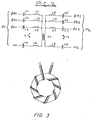
- a passive coupler consists of two tuned networks 11 and 13, each connected to a respective one of the two power supplies, and a transformer T1 coupling the two networks.
- Each network consists of a set of series tuned LC circuits.
- each tuned circuit may conveniently consist of a 0.056 uF capacitor and a 27 uH inductor; for the 231.5/234.5 kHz system, the values may conveniently be 0.033 uF and 15 uH.
- the Figure 2 coupler is for coupling a signal on any one of the phases of a power distribution system P1 to aLL phases of a power distribution system P2.
- phase A1 of system P1 will pass through the two tuned circuits L1-C1 and L4-C4 and one winding of transformer T1, and through the transformer onto all three phases A2, 82 and C2 of system P2 (relative to the neutral N2 of that system).
- one prior art coupler consists merely of a set of 4 capacitors, each coupling corresponding phases of the two systems P1 and P2 (i.e. A1 to A2, B1 to B2, etc.).
- Another prior art system consists merely of a set of 4 LC series tuned circuits, each coupling corresponding phases of the two systems P1 and P2.
- any single capacitor failure could short together two power systems supplying different voltages, with possible serious impact.
- the present system requires at Least three component failures to short two power systems together.
- FIG 3 shows the mechanical structure of transformer T1 of Figure 2.
- the core is a toroidal core with outside diameter of 22mm, inside diameter of 13.7mm and thickness of 6.35mm.
- the two wires are bifiLar wound. That is, in each turn the two wires are adjacent to each other. The use of two colours eases inspection and assembly of the transformer T1 into the passive signal coupler.
- the magnetic properties of the toroidal core are as foLLows:-
- the bifilar winding of the conductors around the toroidal core provides for improved magnetic coupling of the transformer.
- the present passive signal coupler requires the failure of three components to short between the two power distribution systems (2 capacitors and the toroidal core winding).
Landscapes
- Engineering & Computer Science (AREA)
- Power Engineering (AREA)
- Computer Networks & Wireless Communication (AREA)
- Signal Processing (AREA)
- Cable Transmission Systems, Equalization Of Radio And Reduction Of Echo (AREA)
Applications Claiming Priority (2)
| Application Number | Priority Date | Filing Date | Title |
|---|---|---|---|
| US601186 | 1984-04-17 | ||
| US06/601,186 US4675648A (en) | 1984-04-17 | 1984-04-17 | Passive signal coupler between power distribution systems for the transmission of data signals over the power lines |
Publications (2)
| Publication Number | Publication Date |
|---|---|
| EP0159916A2 true EP0159916A2 (de) | 1985-10-30 |
| EP0159916A3 EP0159916A3 (de) | 1986-12-30 |
Family
ID=24406540
Family Applications (1)
| Application Number | Title | Priority Date | Filing Date |
|---|---|---|---|
| EP85302698A Withdrawn EP0159916A3 (de) | 1984-04-17 | 1985-04-17 | Passiver Funkfrequenzsignalkoppler für Starkstromleitungen |
Country Status (5)
| Country | Link |
|---|---|
| US (1) | US4675648A (de) |
| EP (1) | EP0159916A3 (de) |
| JP (1) | JPS60233944A (de) |
| AU (1) | AU575925B2 (de) |
| CA (1) | CA1241719A (de) |
Cited By (1)
| Publication number | Priority date | Publication date | Assignee | Title |
|---|---|---|---|---|
| TWI740303B (zh) * | 2018-12-13 | 2021-09-21 | 日商松下知識產權經營股份有限公司 | 耦合裝置 |
Families Citing this family (85)
| Publication number | Priority date | Publication date | Assignee | Title |
|---|---|---|---|---|
| US6452482B1 (en) * | 1999-12-30 | 2002-09-17 | Ambient Corporation | Inductive coupling of a data signal to a power transmission cable |
| US5351272A (en) * | 1992-05-18 | 1994-09-27 | Abraham Karoly C | Communications apparatus and method for transmitting and receiving multiple modulated signals over electrical lines |
| JPH07508609A (ja) * | 1992-06-30 | 1995-09-21 | エレクトロニック イノベイターズ,インコーポレイテッド | Ac電力ライン搬送波電流lanを用いた分散型知能による工学的被害およびダメージコントロール管理システム |
| US5644286A (en) * | 1993-10-04 | 1997-07-01 | Lockheed Martin Corporation | Power bus digital communication system |
| US5818821A (en) * | 1994-12-30 | 1998-10-06 | Intelogis, Inc. | Universal lan power line carrier repeater system and method |
| US5970127A (en) * | 1997-10-16 | 1999-10-19 | Phonex Corporation | Caller identification system for wireless phone jacks and wireless modem jacks |
| US6055435A (en) * | 1997-10-16 | 2000-04-25 | Phonex Corporation | Wireless telephone connection surge suppressor |
| US6107912A (en) * | 1997-12-08 | 2000-08-22 | Phonex Corporation | Wireless modem jack |
| DE19823234A1 (de) * | 1998-05-25 | 1999-12-02 | Abb Research Ltd | Vorrichtung und Verfahren zur Datenübertragung bzw. Signalauskopplung bei Stromleitern |
| US6480510B1 (en) | 1998-07-28 | 2002-11-12 | Serconet Ltd. | Local area network of serial intelligent cells |
| US6246868B1 (en) | 1998-08-14 | 2001-06-12 | Phonex Corporation | Conversion and distribution of incoming wireless telephone signals using the power line |
| US6243571B1 (en) | 1998-09-21 | 2001-06-05 | Phonex Corporation | Method and system for distribution of wireless signals for increased wireless coverage using power lines |
| US7522878B2 (en) * | 1999-06-21 | 2009-04-21 | Access Business Group International Llc | Adaptive inductive power supply with communication |
| US7212414B2 (en) | 1999-06-21 | 2007-05-01 | Access Business Group International, Llc | Adaptive inductive power supply |
| US7154382B2 (en) * | 1999-12-30 | 2006-12-26 | Ambient Corporation | Arrangement of inductive couplers for data communication |
| IL150830A0 (en) | 2000-01-20 | 2003-02-12 | Current Tech Llc | Method of isolating data in a power line communication network |
| US6668058B2 (en) | 2000-03-07 | 2003-12-23 | Telkonet Communications, Inc. | Power line telephony exchange |
| US7103240B2 (en) * | 2001-02-14 | 2006-09-05 | Current Technologies, Llc | Method and apparatus for providing inductive coupling and decoupling of high-frequency, high-bandwidth data signals directly on and off of a high voltage power line |
| US7248158B2 (en) | 2000-04-14 | 2007-07-24 | Current Technologies, Llc | Automated meter reading power line communication system and method |
| US20020110311A1 (en) * | 2001-02-14 | 2002-08-15 | Kline Paul A. | Apparatus and method for providing a power line communication device for safe transmission of high-frequency, high-bandwidth signals over existing power distribution lines |
| WO2001080441A2 (en) * | 2000-04-14 | 2001-10-25 | Current Technologies, Llc | Digital communications utilizing medium voltage power distribution lines |
| US6998962B2 (en) | 2000-04-14 | 2006-02-14 | Current Technologies, Llc | Power line communication apparatus and method of using the same |
| US6965302B2 (en) | 2000-04-14 | 2005-11-15 | Current Technologies, Llc | Power line communication system and method of using the same |
| AU2001253674A1 (en) * | 2000-04-19 | 2001-11-07 | Current Technologies, Llc | Method and apparatus for interfacing rf signals to medium voltage power lines |
| US6842459B1 (en) | 2000-04-19 | 2005-01-11 | Serconet Ltd. | Network combining wired and non-wired segments |
| US6275144B1 (en) * | 2000-07-11 | 2001-08-14 | Telenetwork, Inc. | Variable low frequency offset, differential, ook, high-speed power-line communication |
| US7245201B1 (en) | 2000-08-09 | 2007-07-17 | Current Technologies, Llc | Power line coupling device and method of using the same |
| US7248148B2 (en) * | 2000-08-09 | 2007-07-24 | Current Technologies, Llc | Power line coupling device and method of using the same |
| US6980089B1 (en) * | 2000-08-09 | 2005-12-27 | Current Technologies, Llc | Non-intrusive coupling to shielded power cable |
| US6449318B1 (en) | 2000-08-28 | 2002-09-10 | Telenetwork, Inc. | Variable low frequency offset, differential, OOK, high-speed twisted pair communication |
| US6519328B1 (en) | 2000-08-28 | 2003-02-11 | Telenetwork, Inc. | Variable low frequency offset, differential, OOK, high-speed twisted pair communication using telephone load coils |
| US6509831B1 (en) * | 2000-09-19 | 2003-01-21 | Kohji Toda | Coupler for digital communication on electric power-lines |
| EP1350381A4 (de) * | 2000-12-15 | 2006-04-26 | Current Tech Llc | Anschalten von faseroptischen daten an elektrische energiesysteme |
| EP1371219A4 (de) | 2001-02-14 | 2006-06-21 | Current Tech Llc | Datenkommunikation über eine stromversorgungsleitung |
| EA005560B1 (ru) | 2001-03-29 | 2005-04-28 | Эмбиент Корпорейшн | Подключение широкополосных модемов к линиям электропитания |
| US7173935B2 (en) * | 2002-06-07 | 2007-02-06 | Current Grid, Llc | Last leg utility grid high-speed data communication network having virtual local area network functionality |
| US7194528B1 (en) | 2001-05-18 | 2007-03-20 | Current Grid, Llc | Method and apparatus for processing inbound data within a powerline based communication system |
| US7245472B2 (en) * | 2001-05-18 | 2007-07-17 | Curretn Grid, Llc | Medium voltage signal coupling structure for last leg power grid high-speed data network |
| US7173938B1 (en) | 2001-05-18 | 2007-02-06 | Current Grid, Llc | Method and apparatus for processing outbound data within a powerline based communication system |
| US7091831B2 (en) * | 2001-10-02 | 2006-08-15 | Telkonet Communications, Inc. | Method and apparatus for attaching power line communications to customer premises |
| US6975212B2 (en) * | 2001-10-02 | 2005-12-13 | Telkonet Communications, Inc. | Method and apparatus for attaching power line communications to customer premises |
| US7170395B2 (en) * | 2001-10-02 | 2007-01-30 | Telkonet Communications, Inc. | Method and apparatus for attaching power line communications to customer premises |
| US7053756B2 (en) | 2001-12-21 | 2006-05-30 | Current Technologies, Llc | Facilitating communication of data signals on electric power systems |
| US7199699B1 (en) | 2002-02-19 | 2007-04-03 | Current Technologies, Llc | Facilitating communication with power line communication devices |
| US7102478B2 (en) | 2002-06-21 | 2006-09-05 | Current Technologies, Llc | Power line coupling device and method of using the same |
| US6982611B2 (en) | 2002-06-24 | 2006-01-03 | Current Technologies, Llc | Power line coupling device and method of using the same |
| US7132819B1 (en) | 2002-11-12 | 2006-11-07 | Current Technologies, Llc | Floating power supply and method of using the same |
| US7076378B1 (en) | 2002-11-13 | 2006-07-11 | Current Technologies, Llc | Device and method for providing power line characteristics and diagnostics |
| US6980090B2 (en) | 2002-12-10 | 2005-12-27 | Current Technologies, Llc | Device and method for coupling with electrical distribution network infrastructure to provide communications |
| US7224272B2 (en) * | 2002-12-10 | 2007-05-29 | Current Technologies, Llc | Power line repeater system and method |
| US6965303B2 (en) | 2002-12-10 | 2005-11-15 | Current Technologies, Llc | Power line communication system and method |
| US7064654B2 (en) * | 2002-12-10 | 2006-06-20 | Current Technologies, Llc | Power line communication system and method of operating the same |
| US7075414B2 (en) * | 2003-05-13 | 2006-07-11 | Current Technologies, Llc | Device and method for communicating data signals through multiple power line conductors |
| US6980091B2 (en) * | 2002-12-10 | 2005-12-27 | Current Technologies, Llc | Power line communication system and method of operating the same |
| US7046124B2 (en) | 2003-01-21 | 2006-05-16 | Current Technologies, Llc | Power line coupling device and method of using the same |
| IL154921A (en) | 2003-03-13 | 2011-02-28 | Mosaid Technologies Inc | A telephone system that includes many separate sources and accessories for it |
| US20040233928A1 (en) * | 2003-05-07 | 2004-11-25 | Telkonet, Inc. | Network topology and packet routing method using low voltage power wiring |
| US20040227623A1 (en) * | 2003-05-07 | 2004-11-18 | Telkonet, Inc. | Network topology and packet routing method using low voltage power wiring |
| US7308103B2 (en) | 2003-05-08 | 2007-12-11 | Current Technologies, Llc | Power line communication device and method of using the same |
| US20060291575A1 (en) * | 2003-07-03 | 2006-12-28 | Berkman William H | Power Line Communication System and Method |
| US7321291B2 (en) * | 2004-10-26 | 2008-01-22 | Current Technologies, Llc | Power line communications system and method of operating the same |
| US7460467B1 (en) | 2003-07-23 | 2008-12-02 | Current Technologies, Llc | Voice-over-IP network test device and method |
| US7113134B1 (en) | 2004-03-12 | 2006-09-26 | Current Technologies, Llc | Transformer antenna device and method of using the same |
| ES2387197T3 (es) * | 2004-08-04 | 2012-09-17 | Quadlogic Controls Corporation | Procedimiento y sistema para el acoplamiento de señales de frecuencia de radio con lineas de potencia de tension media, con dispositivo de auto-sintoma |
| US7170367B2 (en) * | 2004-10-25 | 2007-01-30 | Ambient Corporation | Inductive coupler for power line communications |
| US20060193336A1 (en) * | 2005-02-25 | 2006-08-31 | Telkonet, Inc. | Local area network above cable television methods and devices |
| US20060193313A1 (en) * | 2005-02-25 | 2006-08-31 | Telkonet, Inc. | Local area network above telephony infrastructure |
| US20060193310A1 (en) * | 2005-02-25 | 2006-08-31 | Telkonet, Inc. | Local area network above telephony methods and devices |
| US7265664B2 (en) | 2005-04-04 | 2007-09-04 | Current Technologies, Llc | Power line communications system and method |
| US7307512B2 (en) * | 2005-04-29 | 2007-12-11 | Current Technologies, Llc | Power line coupling device and method of use |
| US20060255930A1 (en) * | 2005-05-12 | 2006-11-16 | Berkman William H | Power line communications system and method |
| US7259657B2 (en) * | 2005-06-21 | 2007-08-21 | Current Technologies, Llc | Multi-subnet power line communications system and method |
| US7675897B2 (en) | 2005-09-06 | 2010-03-09 | Current Technologies, Llc | Power line communications system with differentiated data services |
| US7764943B2 (en) * | 2006-03-27 | 2010-07-27 | Current Technologies, Llc | Overhead and underground power line communication system and method using a bypass |
| US7671701B2 (en) * | 2006-06-09 | 2010-03-02 | Current Technologies, Llc | Method and device for providing broadband over power line communications |
| US7761079B2 (en) * | 2006-06-09 | 2010-07-20 | Current Technologies, Llc | Power line communication device and method |
| US8050803B2 (en) * | 2006-09-20 | 2011-11-01 | Fuji Xerox Co., Ltd. | Power feeding system, electrical apparatus, power feeding apparatus, and computer readable storage medium |
| US7876174B2 (en) * | 2007-06-26 | 2011-01-25 | Current Technologies, Llc | Power line coupling device and method |
| US7795994B2 (en) * | 2007-06-26 | 2010-09-14 | Current Technologies, Llc | Power line coupling device and method |
| US20090085726A1 (en) * | 2007-09-27 | 2009-04-02 | Radtke William O | Power Line Communications Coupling Device and Method |
| US8279058B2 (en) | 2008-11-06 | 2012-10-02 | Current Technologies International Gmbh | System, device and method for communicating over power lines |
| US20110018704A1 (en) * | 2009-07-24 | 2011-01-27 | Burrows Zachary M | System, Device and Method for Providing Power Line Communications |
| JP6047907B2 (ja) * | 2012-04-04 | 2016-12-21 | 株式会社オートネットワーク技術研究所 | 通信装置及び通信システム |
| US9325374B2 (en) * | 2012-06-15 | 2016-04-26 | Qualcomm Incorporated | Powerline communication diversity coupling technique |
| US10130382B2 (en) | 2014-03-27 | 2018-11-20 | Medtronic Xomed, Inc. | Powered surgical handpiece having a surgical tool with an RFID tag |
Family Cites Families (5)
| Publication number | Priority date | Publication date | Assignee | Title |
|---|---|---|---|---|
| US4057793A (en) * | 1975-10-28 | 1977-11-08 | Johnson Raymond E | Current carrier communication system |
| US4188619A (en) * | 1978-08-17 | 1980-02-12 | Rockwell International Corporation | Transformer arrangement for coupling a communication signal to a three-phase power line |
| US4382248A (en) * | 1981-04-09 | 1983-05-03 | Westinghouse Electric Corp. | Remote device for a multi-phase power distribution network communication system |
| US4433284A (en) * | 1982-04-07 | 1984-02-21 | Rockwell International Corporation | Power line communications bypass around delta-wye transformer |
| US4473816A (en) * | 1982-04-13 | 1984-09-25 | Rockwell International Corporation | Communications signal bypass around power line transformer |
-
1984
- 1984-04-17 US US06/601,186 patent/US4675648A/en not_active Expired - Lifetime
-
1985
- 1985-04-01 AU AU40568/85A patent/AU575925B2/en not_active Expired
- 1985-04-11 JP JP60077528A patent/JPS60233944A/ja active Pending
- 1985-04-16 CA CA000479255A patent/CA1241719A/en not_active Expired
- 1985-04-17 EP EP85302698A patent/EP0159916A3/de not_active Withdrawn
Cited By (1)
| Publication number | Priority date | Publication date | Assignee | Title |
|---|---|---|---|---|
| TWI740303B (zh) * | 2018-12-13 | 2021-09-21 | 日商松下知識產權經營股份有限公司 | 耦合裝置 |
Also Published As
| Publication number | Publication date |
|---|---|
| EP0159916A3 (de) | 1986-12-30 |
| AU4056885A (en) | 1985-10-24 |
| JPS60233944A (ja) | 1985-11-20 |
| AU575925B2 (en) | 1988-08-11 |
| US4675648A (en) | 1987-06-23 |
| CA1241719A (en) | 1988-09-06 |
Similar Documents
| Publication | Publication Date | Title |
|---|---|---|
| CA1241719A (en) | Passive signal coupler between power distribution systems for the transmission of data signals over the power lines | |
| US5694108A (en) | Apparatus and methods for power network coupling | |
| US4142178A (en) | High voltage signal coupler for a distribution network power line carrier communication system | |
| CA1081815A (en) | Polyphase distribution network power line carrier communication system | |
| EP0463341B1 (de) | Digitales Datenübertragungssystem mit gleichzeitiger Spannungsübertragung über eine einzige Leitung | |
| US4473816A (en) | Communications signal bypass around power line transformer | |
| US4300126A (en) | Method and apparatus, for power line communications using zero crossing load interruption | |
| CA1287870C (en) | Switch bypass circuit for power line communication systems | |
| US4890089A (en) | Distribution of line carrier communications | |
| US4254402A (en) | Transformer arrangement for coupling a communication signal to a three-phase power line | |
| US20030058085A1 (en) | Power transfer apparatus for concurrently transmitting data and power over data wires | |
| US10056943B2 (en) | System for transmitting and receiving a power line communication signal over the power bus of a power electronic converter | |
| US6529120B1 (en) | System for communicating over a transmission line | |
| US6614326B2 (en) | Power-line coupler having a circuit breaker form or a panelboard employing the same | |
| EP0124260A2 (de) | Trägerfrequenz-Nachrichtensysteme über Stromversorgungsleitungen | |
| US4528677A (en) | Data transmission system | |
| KR102176288B1 (ko) | 시그널링 시스템 | |
| AU2005299526A1 (en) | Arrangement of inductive couplers for data communication | |
| CA2206300A1 (en) | Power line signalling system | |
| JPH07235897A (ja) | 電力線通信装置および電力線通信ネットワーク | |
| JP4712037B2 (ja) | 電力線搬送通信システム | |
| US2154694A (en) | Communication system | |
| AU620058B2 (en) | Power line carrier coupling method and circuit | |
| US9136909B2 (en) | Apparatus for MIMO coupling power line signals into a three-conductor power supply network via two channels | |
| EP2541768A1 (de) | Bypass zur Umgehung eines Hochfrequenzstromleitungskommunikationssignals |
Legal Events
| Date | Code | Title | Description |
|---|---|---|---|
| PUAI | Public reference made under article 153(3) epc to a published international application that has entered the european phase |
Free format text: ORIGINAL CODE: 0009012 |
|
| AK | Designated contracting states |
Designated state(s): BE DE FR GB IT NL |
|
| PUAL | Search report despatched |
Free format text: ORIGINAL CODE: 0009013 |
|
| AK | Designated contracting states |
Kind code of ref document: A3 Designated state(s): BE DE FR GB IT NL |
|
| STAA | Information on the status of an ep patent application or granted ep patent |
Free format text: STATUS: THE APPLICATION HAS BEEN WITHDRAWN |
|
| 18W | Application withdrawn |
Withdrawal date: 19870506 |
|
| RIN1 | Information on inventor provided before grant (corrected) |
Inventor name: ROTH, ROGER R. Inventor name: HRDLICKA, GREGORY A. |