EP0159930A1 - Stator für kleine elektrische Motoren - Google Patents
Stator für kleine elektrische Motoren Download PDFInfo
- Publication number
- EP0159930A1 EP0159930A1 EP85400607A EP85400607A EP0159930A1 EP 0159930 A1 EP0159930 A1 EP 0159930A1 EP 85400607 A EP85400607 A EP 85400607A EP 85400607 A EP85400607 A EP 85400607A EP 0159930 A1 EP0159930 A1 EP 0159930A1
- Authority
- EP
- European Patent Office
- Prior art keywords
- magnets
- stator
- carcass
- parts
- spring
- Prior art date
- Legal status (The legal status is an assumption and is not a legal conclusion. Google has not performed a legal analysis and makes no representation as to the accuracy of the status listed.)
- Granted
Links
- 229910000831 Steel Inorganic materials 0.000 claims description 2
- 230000006835 compression Effects 0.000 claims description 2
- 238000007906 compression Methods 0.000 claims description 2
- 239000010959 steel Substances 0.000 claims description 2
- 229910000639 Spring steel Inorganic materials 0.000 abstract description 4
- 239000003292 glue Substances 0.000 description 2
- 239000011248 coating agent Substances 0.000 description 1
- 238000000576 coating method Methods 0.000 description 1
- 239000000470 constituent Substances 0.000 description 1
- 201000010099 disease Diseases 0.000 description 1
- 208000037265 diseases, disorders, signs and symptoms Diseases 0.000 description 1
- 238000009434 installation Methods 0.000 description 1
- 238000011900 installation process Methods 0.000 description 1
- 238000012423 maintenance Methods 0.000 description 1
- 238000004519 manufacturing process Methods 0.000 description 1
- 238000007747 plating Methods 0.000 description 1
- 229920002994 synthetic fiber Polymers 0.000 description 1
Images

Classifications
-
- H—ELECTRICITY
- H02—GENERATION; CONVERSION OR DISTRIBUTION OF ELECTRIC POWER
- H02K—DYNAMO-ELECTRIC MACHINES
- H02K1/00—Details of the magnetic circuit
- H02K1/06—Details of the magnetic circuit characterised by the shape, form or construction
- H02K1/12—Stationary parts of the magnetic circuit
- H02K1/17—Stator cores with permanent magnets
Definitions
- the present invention relates to a stator for small electric motors comprising permanent magnets held in a carcass for flow circulation.
- the object of the present invention is to remedy these drawbacks and to this end relates to a stator for small electric motors of the type comprising two permanent magnets held in a flow-through carcass by elastic means, characterized in that the elastic means are constituted by a spring made from a steel wire shaped so as to act by compression on the two magnets.
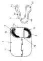
- FIG. 1 In this figure are shown two permanent magnets 2 and 3 housed in a carcass 1 for flow circulation.
- This cylindrical carcass has two flat parts facing each other which on the one hand reduce the size of the stator and on the other hand contribute to the positioning of the permanent magnets 2 and 3 housed in the curved parts 16.
- the longitudinal holding of the magnets is achieved by known means such as stops on the bearing (not shown) and lc folded tabs made in the carcass.
- the immobilization of the magnets is ensured by a spring 4 formed from a spring steel wire.
- This spring 4 comprises two U-shaped parts 4a and 4b, substantially parallel flaring towards their openings which are connected by parts 4c and 4d bent outwards from the U, the free ends of the spring steel wire being at level d 'one of parts 4c and 4d.
- Such a spring makes it possible to obtain a certain time saving in the assembly of the stator; in fact the magnets 2 and 3 being positioned in their location 1b, each in abutment against a tongue lc, it suffices to exert pressure on the parts 4c and 4d of the spring 4, to thread the U-shaped parts 4a and 4b between the magnets, along the carcass until the parts 4c and 4d are in abutment against the free end of the magnets 2 and 3, then to remove the pressure on the parts 4c and 4d, the effect comes out of the parts 4a and 4b then secure the plating of the magnets 2 and 3 against the carcass 1.
- the assembly can also be carried out by positioning the magnets on the spring bearing on the parts 4a and 4b, and in abutment on the parts 4c and 4d, then lowering the carcass around the magnet spring assembly.
- the diameter of the spring steel wire will then be chosen according to the importance of the vibrations to which the stator will be subjected.
Landscapes
- Engineering & Computer Science (AREA)
- Power Engineering (AREA)
- Permanent Field Magnets Of Synchronous Machinery (AREA)
- Dc Machiner (AREA)
- Reciprocating, Oscillating Or Vibrating Motors (AREA)
Applications Claiming Priority (2)
| Application Number | Priority Date | Filing Date | Title |
|---|---|---|---|
| FR8405353A FR2562734B1 (fr) | 1984-04-05 | 1984-04-05 | Stator pour petits moteurs electriques |
| FR8405353 | 1984-04-05 |
Publications (2)
| Publication Number | Publication Date |
|---|---|
| EP0159930A1 true EP0159930A1 (de) | 1985-10-30 |
| EP0159930B1 EP0159930B1 (de) | 1988-06-08 |
Family
ID=9302858
Family Applications (1)
| Application Number | Title | Priority Date | Filing Date |
|---|---|---|---|
| EP85400607A Expired EP0159930B1 (de) | 1984-04-05 | 1985-03-28 | Stator für kleine elektrische Motoren |
Country Status (6)
| Country | Link |
|---|---|
| US (1) | US4668887A (de) |
| EP (1) | EP0159930B1 (de) |
| JP (1) | JPS60229656A (de) |
| DE (1) | DE3563289D1 (de) |
| ES (1) | ES295818Y (de) |
| FR (1) | FR2562734B1 (de) |
Families Citing this family (21)
| Publication number | Priority date | Publication date | Assignee | Title |
|---|---|---|---|---|
| US4764708A (en) * | 1986-12-08 | 1988-08-16 | Roudeski Charles A | Touch control lamp socket interior |
| GB2209880B (en) * | 1987-09-16 | 1991-11-06 | Johnson Electric Ind Mfg | Magnet retainer in an electric motor |
| US5203071A (en) * | 1990-11-05 | 1993-04-20 | Ryobi Motor Products Corp. | Method of motor construction |
| US5160867A (en) * | 1990-11-05 | 1992-11-03 | Ryobi Motor Products Corp. | Motor field assembly |
| DE4128419A1 (de) * | 1991-08-28 | 1993-03-04 | Bosch Gmbh Robert | Elektromotor mit einer vorrichtung zur drehzahl- und/oder drehrichtungserfassung |
| FR2737062B1 (fr) * | 1995-07-21 | 1997-08-29 | Valeo Climatisation | Dispositif pour supporter un moteur electrique entrainant une turbine, notamment pour appareil de chauffage et/ou climatisation de vehicule automobile |
| US5942827A (en) * | 1997-04-03 | 1999-08-24 | Interelectric Ag | Electric motor |
| US6060799A (en) * | 1999-03-31 | 2000-05-09 | Webster Plastics | Magnet carrier for motor housing |
| US6522042B1 (en) | 2000-01-27 | 2003-02-18 | Black & Decker Inc. | Anchoring system for injection molded magnets on a flux ring or motor housing |
| DE10004703A1 (de) * | 2000-02-03 | 2001-08-23 | Bosch Gmbh Robert | Bügelfeder |
| US6522041B1 (en) | 2000-03-08 | 2003-02-18 | Black & Decker Inc. | Permanent magnet motor flux rings |
| DE10031254A1 (de) * | 2000-06-27 | 2002-01-10 | Bosch Gmbh Robert | Bügelfeder |
| US6462448B1 (en) | 2000-07-05 | 2002-10-08 | Black & Decker Inc. | Flux ring for an electric motor |
| US7448556B2 (en) | 2002-08-16 | 2008-11-11 | Henkel Kgaa | Dispenser bottle for at least two active fluids |
| JP4171914B2 (ja) * | 2003-11-27 | 2008-10-29 | 株式会社デンソー | 電動機、これに用いられる弾性部材、および電動機の製造装置 |
| USD561096S1 (en) * | 2005-03-29 | 2008-02-05 | Electrical Core & Motor Mfg. Ltd. | DC-permanent-magnet motor |
| US7986065B2 (en) | 2008-06-04 | 2011-07-26 | Robert Bosch Gmbh | Sealed rolled pole housing for an electric motor |
| US8721383B2 (en) * | 2009-09-09 | 2014-05-13 | Aurora Flight Sciences Corporation | Modular miniature unmanned aircraft with vectored thrust control |
| DE102013205652A1 (de) * | 2013-03-28 | 2014-10-02 | Robert Bosch Gmbh | Magnethaltefeder, sowie elektrische Maschine beinhaltend eine solche, sowie Verfahren zum Herstellen der elektrischen Maschine |
| CN103457367A (zh) * | 2013-09-06 | 2013-12-18 | 杭州科德磁业有限公司 | 一种电机定子的无磁或弱磁磁瓦安装结构以及安装方法 |
| DE102013226942A1 (de) * | 2013-12-20 | 2015-06-25 | Robert Bosch Gmbh | Elektrische Maschine beinhaltend einen Klemmbügel, sowie Verfahren zum Herstellen der elektrischen Maschine |
Citations (3)
| Publication number | Priority date | Publication date | Assignee | Title |
|---|---|---|---|---|
| FR2072540A5 (de) * | 1969-11-28 | 1971-09-24 | Siemens Ag | |
| FR2323262A1 (fr) * | 1975-09-05 | 1977-04-01 | Thomson Brandt | Moteur a inducteurs a aimants permanents |
| WO1982002288A1 (en) * | 1980-12-20 | 1982-07-08 | Ruehle Walter | Electric machine for the starting of a combustion engine |
Family Cites Families (11)
| Publication number | Priority date | Publication date | Assignee | Title |
|---|---|---|---|---|
| AT198829B (de) * | 1955-08-08 | 1958-07-25 | Fleischmann Geb | Magnetmotor |
| DE1074698B (de) * | 1957-07-12 | 1960-02-04 | Busch-Jaeger Dürener Metallwerke Aktiengesellschaft, Lüdenscheid | Installationsgerät wie Schalter, Selbstschalter, Sicherungselement u. dgl. mit einer am Boden des Sockels vorgesehenen Einrichtung zur Befestigung auf Tragschienen bei Schalt- und Verteilungsanlagen |
| US3258622A (en) * | 1963-06-06 | 1966-06-28 | Borg Warner | Magnet retainers for a dynamoelectric machine |
| FR1583851A (de) * | 1968-05-10 | 1969-12-05 | ||
| US3521096A (en) * | 1968-10-14 | 1970-07-21 | Ford Motor Co | Permanent magnet dynamoelectric machine structure |
| US3631277A (en) * | 1970-12-15 | 1971-12-28 | Ford Motor Co | Stator for a permanent magnet dynamoelectric machine including novel magnet retaining means |
| US3790830A (en) * | 1972-08-09 | 1974-02-05 | Gen Motors Corp | Magnet mounting clip for a dynamoelectric machine |
| US4071794A (en) * | 1975-11-10 | 1978-01-31 | General Motors Corporation | DC motor with permanent magnet retaining structure |
| DE2735778A1 (de) * | 1977-08-09 | 1979-03-01 | Bosch Gmbh Robert | Stator fuer elektrische maschinen |
| DE2810215C3 (de) * | 1978-03-09 | 1993-12-02 | Bosch Gmbh Robert | Verfahren zum Aufbringen eines zusätzlichen Rückschlusses auf das Gehäuse einer elektrischen Maschine |
| JPS563561A (en) * | 1979-06-22 | 1981-01-14 | Hitachi Ltd | Magnet fixing means for small motor |
-
1984
- 1984-04-05 FR FR8405353A patent/FR2562734B1/fr not_active Expired
-
1985
- 1985-03-28 DE DE8585400607T patent/DE3563289D1/de not_active Expired
- 1985-03-28 EP EP85400607A patent/EP0159930B1/de not_active Expired
- 1985-04-03 ES ES1985295818U patent/ES295818Y/es not_active Expired
- 1985-04-03 US US06/719,735 patent/US4668887A/en not_active Expired - Fee Related
- 1985-04-04 JP JP60071885A patent/JPS60229656A/ja active Pending
Patent Citations (3)
| Publication number | Priority date | Publication date | Assignee | Title |
|---|---|---|---|---|
| FR2072540A5 (de) * | 1969-11-28 | 1971-09-24 | Siemens Ag | |
| FR2323262A1 (fr) * | 1975-09-05 | 1977-04-01 | Thomson Brandt | Moteur a inducteurs a aimants permanents |
| WO1982002288A1 (en) * | 1980-12-20 | 1982-07-08 | Ruehle Walter | Electric machine for the starting of a combustion engine |
Non-Patent Citations (1)
| Title |
|---|
| PATENT ABSTRACTS OF JAPAN, vol. 5, no. 51 (E-51)[723], 10 avril 1981, page 123 E 51; & JP-A-56 003 561 (HITACHI EISAKUSHO K.K.) 14-01-1981 * |
Also Published As
| Publication number | Publication date |
|---|---|
| EP0159930B1 (de) | 1988-06-08 |
| ES295818Y (es) | 1987-12-16 |
| DE3563289D1 (en) | 1988-07-14 |
| ES295818U (es) | 1987-06-16 |
| FR2562734A1 (fr) | 1985-10-11 |
| FR2562734B1 (fr) | 1988-05-06 |
| JPS60229656A (ja) | 1985-11-15 |
| US4668887A (en) | 1987-05-26 |
Similar Documents
| Publication | Publication Date | Title |
|---|---|---|
| FR2562734A1 (fr) | Stator pour petits moteurs electriques | |
| EP2789076B1 (de) | Vorrichtung zum führen eines satzes elektrischer drähte für einen elektromotorrotor | |
| FR2823616A1 (fr) | Machine electrique comportant au moins un detecteur de champ magnetique | |
| EP1251623A1 (de) | Stator für elektrische Maschine mit einzeln herauslösbaren Spulen | |
| EP0431514B1 (de) | Motor mit Magneten der Flusskonzentrationsbauart | |
| JPS5942547B2 (ja) | 回転電機のブラシ保持装置 | |
| FR2550397A3 (fr) | Moteur a commutateur excite par aiment permanent | |
| EP1251620A1 (de) | Drehende Maschine mit einem aus Abschnitten zusammengesetzter Rotor | |
| EP1264387B1 (de) | Bürstenhalter mit lamellierten bürsten, feder und dämpfer | |
| EP1249919A1 (de) | Rotor einer rotierenden elektrischen Maschine | |
| EP0368689B1 (de) | Radzierblende | |
| EP0069030B1 (de) | Einzelantrieb mit Elektromotor für Zwirnspindel | |
| EP1251622A1 (de) | Spule für drehende elektrische Maschine | |
| FR2598044A1 (fr) | Dispositif pour diminuer le bruit emis par les machines electriques notamment par les generateurs de courant alternatif de vehicules automobiles | |
| FR2591399A1 (fr) | Rotor a poles a griffes pour un generateur electrique, tel que alternateur de vehicules automobiles | |
| CN102474060B (zh) | 用于电机的刷架 | |
| FR3010850A1 (fr) | Bridage d'un interconnecteur sur un stator | |
| FR2687862A1 (fr) | Module inducteur d'un moteur lineaire asynchrone et moteur en faisant application. | |
| FR2611323A1 (fr) | Rotor de machine tournante electrique | |
| FR2596929A1 (fr) | Machine dynamo-electrique, notamment alternateur de vehicule automobile | |
| FR3053543A1 (fr) | Machine electrique tournante munie d'un interconnecteur fixe sur le corps du stator | |
| FR3069973A1 (fr) | Rotor de machine electrique tournante muni d'un flasque ayant une fonction de maintien d'aimants permanents | |
| FR2525308A1 (fr) | Dispositif antivibrations pour contacteur de demarreur pour moteurs a combustion interne | |
| EP0010339B1 (de) | Stator für eine elektrische Rotationsmaschine und elektrische Rotationsmaschine mit einem derartigen Stator | |
| EP3389165B1 (de) | Verbesserte führungsvorrichtung einer gesamtheit von elektrischen drähten für rotor eines elektromotors |
Legal Events
| Date | Code | Title | Description |
|---|---|---|---|
| PUAI | Public reference made under article 153(3) epc to a published international application that has entered the european phase |
Free format text: ORIGINAL CODE: 0009012 |
|
| AK | Designated contracting states |
Designated state(s): BE DE GB IT |
|
| 17P | Request for examination filed |
Effective date: 19860117 |
|
| 17Q | First examination report despatched |
Effective date: 19870413 |
|
| GRAA | (expected) grant |
Free format text: ORIGINAL CODE: 0009210 |
|
| AK | Designated contracting states |
Kind code of ref document: B1 Designated state(s): BE DE GB IT |
|
| ITF | It: translation for a ep patent filed | ||
| REF | Corresponds to: |
Ref document number: 3563289 Country of ref document: DE Date of ref document: 19880714 |
|
| GBT | Gb: translation of ep patent filed (gb section 77(6)(a)/1977) | ||
| PG25 | Lapsed in a contracting state [announced via postgrant information from national office to epo] |
Ref country code: GB Effective date: 19890328 |
|
| PG25 | Lapsed in a contracting state [announced via postgrant information from national office to epo] |
Ref country code: BE Effective date: 19890331 |
|
| PLBE | No opposition filed within time limit |
Free format text: ORIGINAL CODE: 0009261 |
|
| STAA | Information on the status of an ep patent application or granted ep patent |
Free format text: STATUS: NO OPPOSITION FILED WITHIN TIME LIMIT |
|
| 26N | No opposition filed | ||
| BERE | Be: lapsed |
Owner name: DUCELLIER ET CIE Effective date: 19890331 |
|
| GBPC | Gb: european patent ceased through non-payment of renewal fee | ||
| PG25 | Lapsed in a contracting state [announced via postgrant information from national office to epo] |
Ref country code: DE Effective date: 19891201 |