EP0159940B1 - Bürste mit federnd einziehbaren Borsten, insbesondere zum Bürsten von unregelmässigen Oberflächen, wie Zähnen - Google Patents
Bürste mit federnd einziehbaren Borsten, insbesondere zum Bürsten von unregelmässigen Oberflächen, wie Zähnen Download PDFInfo
- Publication number
- EP0159940B1 EP0159940B1 EP85400703A EP85400703A EP0159940B1 EP 0159940 B1 EP0159940 B1 EP 0159940B1 EP 85400703 A EP85400703 A EP 85400703A EP 85400703 A EP85400703 A EP 85400703A EP 0159940 B1 EP0159940 B1 EP 0159940B1
- Authority
- EP
- European Patent Office
- Prior art keywords
- membrane
- face
- brush
- wall
- tufts
- Prior art date
- Legal status (The legal status is an assumption and is not a legal conclusion. Google has not performed a legal analysis and makes no representation as to the accuracy of the status listed.)
- Expired
Links
- 238000004140 cleaning Methods 0.000 title 1
- 230000001788 irregular Effects 0.000 title 1
- 239000012528 membrane Substances 0.000 claims abstract description 104
- 230000002093 peripheral effect Effects 0.000 claims description 33
- 239000000463 material Substances 0.000 claims description 8
- 230000000295 complement effect Effects 0.000 claims description 4
- 229920001971 elastomer Polymers 0.000 claims description 4
- 239000000806 elastomer Substances 0.000 claims description 4
- 244000043261 Hevea brasiliensis Species 0.000 claims description 3
- 229920003052 natural elastomer Polymers 0.000 claims description 3
- 229920001194 natural rubber Polymers 0.000 claims description 3
- 239000004816 latex Substances 0.000 claims description 2
- 229920000126 latex Polymers 0.000 claims description 2
- 229920001084 poly(chloroprene) Polymers 0.000 claims description 2
- 229920001296 polysiloxane Polymers 0.000 claims description 2
- 210000004209 hair Anatomy 0.000 description 13
- 239000011324 bead Substances 0.000 description 9
- 230000001680 brushing effect Effects 0.000 description 8
- 230000005489 elastic deformation Effects 0.000 description 7
- 239000002609 medium Substances 0.000 description 3
- 238000012550 audit Methods 0.000 description 2
- 238000005452 bending Methods 0.000 description 2
- 239000004033 plastic Substances 0.000 description 2
- 229920003023 plastic Polymers 0.000 description 2
- 238000003466 welding Methods 0.000 description 2
- 240000008042 Zea mays Species 0.000 description 1
- 230000006978 adaptation Effects 0.000 description 1
- 230000032683 aging Effects 0.000 description 1
- 239000012736 aqueous medium Substances 0.000 description 1
- 210000004027 cell Anatomy 0.000 description 1
- 230000006835 compression Effects 0.000 description 1
- 238000007906 compression Methods 0.000 description 1
- 230000004927 fusion Effects 0.000 description 1
- 230000037431 insertion Effects 0.000 description 1
- 238000003780 insertion Methods 0.000 description 1
- 239000007788 liquid Substances 0.000 description 1
- 230000035515 penetration Effects 0.000 description 1
- 238000007789 sealing Methods 0.000 description 1
- 230000035882 stress Effects 0.000 description 1
- 229920002994 synthetic fiber Polymers 0.000 description 1
- 229940034610 toothpaste Drugs 0.000 description 1
- 239000000606 toothpaste Substances 0.000 description 1
Images

Classifications
-
- A—HUMAN NECESSITIES
- A46—BRUSHWARE
- A46B—BRUSHES
- A46B5/00—Brush bodies; Handles integral with brushware
- A46B5/002—Brush bodies; Handles integral with brushware having articulations, joints or flexible portions
- A46B5/0025—Brushes with elastically deformable heads that change shape during use
- A46B5/0029—Head made of soft plastics, rubber or rubber inserts in plastics matrix
-
- A—HUMAN NECESSITIES
- A46—BRUSHWARE
- A46B—BRUSHES
- A46B7/00—Bristle carriers arranged in the brush body
- A46B7/06—Bristle carriers arranged in the brush body movably during use, i.e. the normal brushing action causing movement
Definitions
- the present invention relates to a brush with retractable bristles, in particular for brushing surfaces of complex relief and for example for brushing teeth.
- Traditional brushes have tufts of bristles, a first end of which is trapped in a brush head, of which this end is integral, and of which a second end is free and used for brushing.
- the respective free ends of the different tufts have an envelope surface which can deform slightly by bending the bristles in contact with a surface to be brushed but which, however, when this surface has too pronounced a relief, cannot adapt with sufficient precision on this surface and, above all, ensure contact with the latter with sufficient pressure everywhere to ensure correct brushing.
- the object of the present invention is to remedy this drawback, by proposing a brush whose tufts of bristles can retract elastically, independently of one another, towards the inside of the brush so as to allow permanent adaptation of the surface. envelope defined by the free ends of these tufts on the surface to be brushed, and this without any noticeable difference in the intensity of the force applied to the different zones of the latter by the different tufts of bristles.
- the brush head in order to allow said point elastic deformation of the membrane, has a cavity facing all of the bores in the wall, in common with all of these bores, opposite to the first face of the wall with respect to the membrane and the membrane is made of an isotropic material and has its own anisotropy such that the tufts of hair can retract elastically, independently of each other, towards the interior of said cavity.
- a tensioning of the membrane will however favor this privileged point deformability in the direction of its thickness.
- this prior art proceeds from a type of reasoning according to which, to ensure independence in the retraction and the elastic return of each tuft of hairs, it is necessary to associate with it a clean elastic return member.
- the support grid precisely has the function of dissociating the membrane into as many zones as there are tufts and of ensuring mutual independence of these zones, in the spirit with which the first of the aforementioned American patents presents as alternatively an assembly comprising a multiplicity of helical springs each of which is associated with a tuft of bristles, replacing the association of a membrane and a support grid.
- the present invention proceeds from a radically different philosophy since it proposes to associate with all of the tufts of hair, defining a discontinuous structure due to their totally independent mounting, a single, continuous return member from a tuft to the other, by ensuring independence of movement and elastic return of the different tufts by using a specific quality of this return member, namely the membrane, and not by the structural device that constitutes a support of a membrane on a grid.
- the membrane of a brush produced in accordance with the present invention therefore stressed in terms of its inherent deformation possibilities, necessarily has a considerably increased longevity in comparison with the membrane of a brush produced in accordance with the teachings of the two aforementioned American patents.
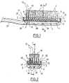
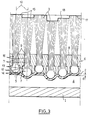
- FIGS. 1 to 3 designates a flat head of a brush such as a toothbrush, integral with a handle 27 and having a flat face 2 on which this head 1 carries a plurality of tufts 3 bristles, arranged in respective directions approximately parallel to one another and perpendicular to face 2.
- the face 2 is hollowed out with a cavity 4 which the face 2 surrounds on all sides to define the periphery and which is closed, at the level of this face 2, by a membrane 5 made of an isotropic elastomer material chosen for its ability to communicate to the membrane its possibility of undergoing substantially punctual elastic deformations and its own anisotropic character, defined above.
- An artificial balloon of the type used for making advertising balloons of a thickness of the order of 3 tenths of a mm, based on natural rubber, has been successfully used as a membrane.
- the membrane 5 is secured in the stretched state with the brush head 1, on the flat face 2 thereof, over the entire periphery of the cavity 4 which the membrane 5 closes tightly, so that the cavity and the membrane enclose an air cushion whose presence advantageously increases the characteristic punctual deformability of the membrane in the direction of its thickness.
- the cavity 4 can be opened by means allowing free circulation, with the outside of this cavity 4, of air and of the medium in which the brush can be brought to evolve in certain applications, for example toothpaste in an aqueous medium in the case of a toothbrush.
- a membrane 6 in the stretched state is superimposed flat, opposite the cavity 4, a plate 6 made as the brush head 1 in a rigid material and for example in plastic.
- This plate 6 is secured to the brush head 1, with which it encloses the membrane 5 continuously over the entire periphery of the cavity 4.
- the plate 6 thus forms a rigid whole with the brush head 1, of which it could moreover form an integral part in other examples of implementation of the present invention, as will emerge from the description of FIGS. 4 and 5.
- the plate 6 has a first flat face 7 thus turned towards the membrane 5, with which it is in flat contact when this membrane 5 is stretched, and towards the cavity 4, and a face 8 also flat, parallel to the face 7, and turned away from the membrane 5, towards the outside of the brush head 1.
- a continuous peripheral zone 21 of the membrane 5 is pinched between the edge 19 of the plate 6 and the flange 20 of the face 2, which ensures the joining of the membrane with the head 1 and the plate 6, as well as the mutual solidarity of the latter.
- This joining can be improved by bonding or mutual heat-sealing of the plate 6, at the junction 22 of the edge 19 of the plate 6 and of the face 8 thereof, and of the flange 20, by an edge 23 of the latter flush the face 8 of the plate 6, around the membrane 5.
- the membrane 5 remains free both with respect to the plate 6 and with respect to the brush head 1.
- the plate 6 is pierced right through with bores 9 in a number identical to that of the tufts 3, of which each of these bores 9 receives one, facing the cavity 4.
- each bore 9 has two cylindrical zones of revolution about the same respective axis 10 approximately perpendicular to the faces 7 and 8, due to a zone 11 of smaller diameter, adjacent to the face 8 of the plate 6 , and a zone 12 of larger diameter, adjacent to the face 7.
- the tuft 3 has between these two ends 14 and 15 an intermediate zone 16 mounted to slide, along the axis 10, in the zone 11 of the bore 9 and having for this purpose, transverse to the axis 10, a section as close as possible to that of the zone 11 .
- the bristles of the tuft 3 are agglomerated for example by welding in the frequent case where these bristles are made of synthetic material, and the increase in section transverse of the tuft at the first end 14 thereof can advantageously be obtained by fusion in this case, or by any other means.
- the first end 14 of the tuft 3 remains independent of the membrane 5, that is to say is not secured to the latter.
- the hairs of this tuft are on the other hand independent, over a length suitable for communicating to the hairs of the entire tuft flexibility desired.
- the ends 15 of the different tufts define a perfectly defined envelope surface 18, for example planar.
- the shape of the envelope surface 18 thus adapts precisely to that of the surface 17.
- the tufts 3 released by the comparatively projecting zones tend to return to their initial position by sliding in the opposite direction under the action of the membrane 5 which, tending elastically to resume its initial shape , tends to bring their first end 14 into contact with the shoulder 13, while the tufts 3 brought into contact with comparatively projecting areas retract in the manner described above.
- the shape of the envelope surface 18 and that of the faces 2 of the brush head and 7 of the plate 6, that is to say also the shape of the membrane 5 in the stretched state between these faces 2 and 7, may be chosen different from those which have been described.
- the shape and nature of the tufts 3, as well as their distribution can be chosen at will and possibly modulated to communicate different characteristics to different areas of the same brush.
- the very structure of the brush head and the way in which the membrane is connected to it can have many variations and, in particular, instead of being attached to the brush head facing a cavity of the latter, the perforated wall guiding the tufts of bristles to sliding can form an integral part of the brush head with which the membrane can be secured peripherally, continuously, by any means otherwise allowing free movement of the membrane, and for example by a cover delimiting opposite the latter, except in the peripheral connection zone, a cavity allowing such movement.
- FIG. 4 where 101 has designated a flat brush head, integral with a handle not shown and comprising a flat wall 102, delimited essentially by two plane faces 103, 104 mutually parallel , and a rim 105 continuously bordering the wall 102 by forming a projection relative to the face 104 thereof and having in particular a continuous inner peripheral face 106, perpendicular to the face 104 and disjoined from the latter to which it is connected via a continuous groove 107, immediately adjacent to the face 106 and recessed with respect to a plane virtual extension 108 of the face 104, and by a continuous flange 109 connecting the groove 107 to the face 104 and forming above the planar extension 108 of the face 104 a projection of constant value d less than the value D, also constant, of the projection formed by the flange 105, and in particular by the inner peripheral face 106 thereof, byrelative to the plan 108 extension of the face 104.
- the wall 103 is pierced right through with a plurality of bores 110 each of which has its own axis 111 perpendicular to the faces 103 and 104 and opens into one and the other of these, in particular near the flange 109 but not therein.
- each of the bores 110 is thus delimited by a peripheral face 112 of cylindrical revolution around the corresponding axis 111, with a constant diameter.
- Each of the bores 110 like each of the bores 9 of the plate 6, is intended to receive and guide, when sliding along the corresponding axis 111, a respective tuft of bristles 113 at any point comparable to one of the tufts 3 described. with reference to Figures 1 to 3.
- the tuft 113 has a first end 114 for mounting on the brush head 101 by confinement, inside the latter, between the flat wall 102 and a membrane 117 as will appear below, a second end 115 as for it free and constituting the brushing end, as well as an intermediate zone 116 immediately adjacent to the first end 114 and passing through the flat wall 102 via the corresponding bore 110.
- the bristles of the tuft are free between the zone 116 of the latter and its end 115 while they are advantageously agglomerated in the zone 116, so that the latter has a stable cylindrical envelope of revolution around the axis 111 with a diameter as close as possible to that of the face 112 of the bore 106, and that it thus establishes between the face 112 and the tuft of bristles 113 a guide to the relative sliding along the axis 111 with a minimum of obstacles.
- the bristles of the tuft are also agglomerated at the first end 114, which has transverse to the axis 111 dimensions greater than the diameter of the face 112 so that the first end 114 can, by pressing on the face 104 of the wall 2 around the bore 110, constitute a stop at against a sliding of the tuft 113 relative to the wall 102 in a direction going from the wall 104 towards the wall 103 parallel to the axis 111.
- the tuft 113 has dimensions between its two ends 114 and 115 such that, when such a stop of the end 114 against the face 104 is established, the end 115 of the tuft forms with respect to the face 103 of the wall 102 and with respect to the intermediate zone 116 of the tuft a projection of a value suitable for imparting any desired flexibility to the hairs of the tuft.
- the first end 114 of the tuft of hairs 113 forms with respect to the face 104, when this end 114 is in abutment on this face 104, a projection of value A intermediate between D and d, and closer to d than from D.
- this same dimension A is found on each of the tufts 113 each of which thus forms a projection of value A - d relative to the flange 109, perpendicular to the face 104, when the respective first ends such as 114 of the different tufts such as 113 are in abutment against the face 104 of the wall 102.
- the head 101 which has just been described integrally carries an attached cover 118 formed, like the brush head 101, of a flat wall 119 delimited in particular by two plane faces 135 and 136 plane and mutually parallel, and of a rim 120 projecting from the face 106 of the wall 119.
- the rim 120 is fitted into the rim 105 of the brush head 101, and placed in contact with the inner peripheral face 106 of this rim 105.
- Respective shoulders 122 and 123 of the edges 105 and 120 define, by a mutual stop advantageously accompanied by mutual joining for example by high frequency welding if the cover 118 and the brush head 101 are made of a plastic material, or by any other suitable means, a relative position of the cover 118 and the head 101 such that the face 136 of the wall 119, placed opposite the face 104, is parallel to the latter and spaced from this face 104 by a distance 8 greater at the sum of A and a current thickness e, of the membrane 117.
- the face 136 has dimensions in plan at least equal to those of the face 104, so as to present a zone opposite each zone of this face 104 in a direction perpendicular thereto, so that it remains between the face 136 and the membrane 117, assumed to be applied to the respective ends such as 114 of the different tufts of bristles such as 113 themselves in abutment against the face 104 of the flat wall 102, a possibility of movement of the membrane 117 and first ends such as 114 tufts such as 113.
- the rim 120 has a continuous edge face 125, parallel to the face 136, and which connects the outer peripheral face 121 of the rim 120 to an inner peripheral face 127 thereof, which connects the face 125 to the face 136 at least approximately perpendicular to either of these faces.
- the edge face 125 of the flange 120 is placed opposite the groove 107 in a direction perpendicular to the virtual plane extension 108 of the face 104, and there remains between an edge 128 connecting this edge face 125 and the inner peripheral face 127 of the rim 120, on the one hand, the rim 109 on the other hand, a continuous annular space 129 having, perpendicular to the extensions respective 108 and 124 of the faces 104 and 136, that is to say also on the edge face 125, a thickness F-1 equal or approximately equal to the current thickness e, of the membrane 117.
- the annular space 129 thus constitutes a narrowing in comparison with a space 130 defined jointly by the groove 107 and the face 125 of the rim 120, and this arrangement is used to immobilize, inside the groove 107 by means of the face 125 of the rim 120, a continuous peripheral bead 131 that the membrane 117 has in excess thickness with respect to its current thickness e ,.
- the membrane 117 engages in the space 129 without its peripheral bead 131 being able to escape from the space 130.
- the bead 131 has, when it is not trapped in the space 130, a geometry different from that of this space, so that its trapping in this space 130 results in an elastic compression of this bead, contributing to his restraint.
- the membrane 117 is preferably chosen such that, when it is released from the brush head 101 and the cover 118, it has a flat shape, of constant current thickness e i except at the level of its continuous peripheral bead 131, so that the mounting of this membrane 117 in the brush head 101 and the imprisonment of the bead 131 in the space 130 result, by imposing a deflection of the membrane against the edge 128 on the one hand, and against the respective first ends such as 114 of the different tufts of hair such as 113 those closest to the rim 109, on the other hand, placing this membrane 17 in prestressing tension even when the respective first ends such as 114 of tufts of bristles such as 113 are in abutment against the face 104 of the wall 102.
- the face 136 of the flat wall 119 and the face 127 of the rim 120 define, opposite the membrane 117 and all of the respective first ends such as 114 of the different tufts of bristles 113, a single, common cavity 132 towards which the membrane 117 can flex freely, locally, when one or other of the tufts of hair such as 113 is stressed by a force directed towards this cavity 132 approximately parallel to the corresponding axis 111, and exerts an elastic return on this tuft 113 to bring its first end 114 into abutment against the face 104 when such a stress stops.
- the cavity 132 may be closed in a sealed manner, in particular by the membrane 117 and the cover 118 or, on the contrary, when the brush is intended to work in a liquid medium, ensuring a free circulation of this medium between the cavity 132 and the exterior thereof by suitably sized orifices, arranged for example in the cover 118.
- FIG. 5 presents great analogies with those of FIG. 4, and FIG. 5 has been designated under the references 201 to 208, 210 to 224, 226 to 227, 231, 232, 235, 236, the elements described respectively under the references 101 to 108, 110 to 124, 126, 127, 131, 132, 135, 136 in connection with the variant illustrated in FIG. 4.
- the groove 207 corresponding to the groove 107 is connected directly on the one hand to the inner peripheral face 206 of the flange 205, corresponding to the inner peripheral face 106 of the flange 105 , and on the other hand to the face 204 of the wall 202, corresponding to the face 104 of the face 102, in the absence of an equivalent to the flange 109 in the case of the variant of FIG. 5.
- peripheral external 221 and internal 227 faces respectively of the rim 220 of the cover 218 are not connected to each other by a flat edge face like the face 125, but by two faces 233 , 234 defining for the rim 220 a beveled end 226 engaged in the groove 207 of the brush head 201 with the insertion of a continuous peripheral zone 237 of the membrane 217 including the bead 231, disposed around this continuous peripheral zone 237, is fitted into a continuous peripheral groove 238 that the outer peripheral face 221 of the rim 220 of the cover 218 has at its junction with the face 233, facing the face 206 of the rim 205 of the brush head 201, in a mean plane 239 intermediate between the respective planar extensions 208 and 224 of the faces 204 and 236 but closer to the extension 208 than to the extension 224.
- the groove 207 has a flank face 241 parallel to the face 233 at a distance e 2 from the latter close to the current thickness e 1 of the membrane 217 but less than this thickness e 2 so as to ensure that the peripheral zone 237 of the membrane is clamped between the faces 233 and 241.
- the face 241 thus joins the face 206 of the rim 205 to a flat bottom face 242, located opposite the edge 240 at the distance 92 from the latter, and this face 242 is connected to the face 204 by a face 243 placed opposite face 234 with a minimum mutual spacing of value e 2 .
- the faces 243 and 234 diverge from each other in the direction of a distance from the edge 240 and from the face 242, and are oriented so that the membrane 217, bending against the edge 240 and in contact with the respective first ends such as 214 tufts of hair such as 213 closest to the groove 207, does not undergo any other deflection between these two deflections, as well when the first respective ends such as 214 of the tufts such as 213 closest to the groove 207 are in abutment against the face 204 of the wall 202, as illustrated, only when, under the action of a thrust applied to the ends such as 215 of these tufts such that 213, the membrane 217 is pushed back by the ends such as 214 of these tufts in its zone of deflection against these ends 214.
- the membrane 217 can also have a flat conformation, when it is not fitted by its peripheral bead 231 in the groove 238 of the rim 220 of the cover 218 and bent against the edge 240 of on the one hand, and against the first ends such as 214, tufts of hair such as 213 closest to the throat 207.
- the choice of the material constituting the membrane 5, and of the thickness thereof, can easily be made by a person skilled in the art as a function of the mechanical characteristics, in particular of elas ticity, to communicate to this membrane.
- the material will advantageously be chosen from the group comprising elastomers of the natural or synthetic latex type, such as polychloroprene, natural rubber preferably treated so as to have improved resistance to aging, and silicones.
- the thickness of the membrane in the relaxed state will generally vary on the order of 1 tenth of a mm to less than 1 mm in the case of toothbrushes, to then provide a possibility of amplitude of localized elastic deformation, known as point, of the membrane of the order of 0.5 mm to 5 mm for a force of the order of 2N (approximately 200 gf) to 7.5 N (approximately 750 gf) applied in a distributed manner to all the tufts of bristles along the respective mean directions thereof, that is to say along the respective axes of the corresponding bores.
- this possible amplitude of localized elastic deformation of the membrane will be of the order of 3 mm under a pressure of the order of 6.10 4 Pa (approximately 6 gf / mm 2 ) between the tufts of bristles 3 and the teeth in the case of a brush comprising about thirty tufts, that is to say for a total effort of application of the brush on the teeth, in the average direction of the tufts, of the order of 2N (approximately 200 gf ), generally considered normal, the return of the membrane to its initial conformation after maximum point deformation, under normal conditions of use of the toothbrush, will be carried out in less than 1 second, and preferably in a time of l 1 tenth of a second.
- the membrane will preferably be chosen so that all of the tufts retract under the action of a force of contact with the surface to be brushed, in an average direction of these tufts, considered to be usual, optimal in this application, and for each tuft to return to a non-shrunk state in a time compatible with the frequency of any irregularities in the surface to be brushed, taking account of a usual speed of course of it by the brush.
Landscapes
- Brushes (AREA)
- Pens And Brushes (AREA)
- Cleaning In General (AREA)
Claims (15)
dadurch gekennzeichnet,
Priority Applications (1)
| Application Number | Priority Date | Filing Date | Title |
|---|---|---|---|
| AT85400703T ATE46253T1 (de) | 1984-04-13 | 1985-04-09 | Buerste mit federnd einziehbaren borsten, insbesondere zum buersten von unregelmaessigen oberflaechen, wie zaehnen. |
Applications Claiming Priority (2)
| Application Number | Priority Date | Filing Date | Title |
|---|---|---|---|
| FR8405896A FR2562775B1 (fr) | 1984-04-13 | 1984-04-13 | Brosse a poils retractables elastiquement, notamment pour le brossage de surfaces de relief complexe telles que les dents |
| FR8405896 | 1984-04-13 |
Publications (3)
| Publication Number | Publication Date |
|---|---|
| EP0159940A2 EP0159940A2 (de) | 1985-10-30 |
| EP0159940A3 EP0159940A3 (en) | 1987-05-27 |
| EP0159940B1 true EP0159940B1 (de) | 1989-09-13 |
Family
ID=9303154
Family Applications (1)
| Application Number | Title | Priority Date | Filing Date |
|---|---|---|---|
| EP85400703A Expired EP0159940B1 (de) | 1984-04-13 | 1985-04-09 | Bürste mit federnd einziehbaren Borsten, insbesondere zum Bürsten von unregelmässigen Oberflächen, wie Zähnen |
Country Status (9)
| Country | Link |
|---|---|
| US (1) | US4633542A (de) |
| EP (1) | EP0159940B1 (de) |
| JP (1) | JPS60232109A (de) |
| AT (1) | ATE46253T1 (de) |
| CA (1) | CA1255859A (de) |
| DE (1) | DE3572919D1 (de) |
| ES (1) | ES8700564A1 (de) |
| FR (1) | FR2562775B1 (de) |
| PT (1) | PT80267B (de) |
Families Citing this family (59)
| Publication number | Priority date | Publication date | Assignee | Title |
|---|---|---|---|---|
| FR2599604B1 (fr) * | 1986-06-04 | 1991-04-26 | Taravel Bernard | Dispositif rotatif de brossage |
| EP0437109A3 (en) * | 1990-01-12 | 1991-10-30 | Trc Acquisition Corporation | Hand-held corded vacuum cleaner |
| US5218736A (en) * | 1990-01-12 | 1993-06-15 | Trc Acquisition Corporation | Vacuum cleaner |
| IL96413A0 (en) * | 1990-11-20 | 1991-08-16 | Ohad Paz | Brush including spring-mounted bristle holders |
| AU660955B2 (en) * | 1990-11-20 | 1995-07-13 | Oraline International B.V. | Brush including spring-mounted bristle holders |
| KR920017602A (ko) * | 1991-03-22 | 1992-10-21 | 김지완 | 탄성솔(cusion brush) |
| DE69230340T2 (de) * | 1991-03-27 | 2000-03-30 | Smithkline Beecham Consumer Healthcare Gmbh | Zahnbürste mit federnder Verbindungszone zwischen Bürstenkopf und Griff |
| US5269038A (en) * | 1991-03-29 | 1993-12-14 | Bradley Terry G | Rocker toothbrush |
| US5398366A (en) * | 1991-03-29 | 1995-03-21 | Bradley; Terry | Rocker toothbrush |
| GB2262434A (en) * | 1991-12-13 | 1993-06-23 | Ishikawajima Harima Heavy Ind | A brush assembly suitable for cleaning irregularly shaped surfaces such as hot metal casting rolls |
| US5355546A (en) * | 1992-12-11 | 1994-10-18 | Scheier Paul A | Toothbrush with resilient flexible bristle support |
| US5454133A (en) * | 1993-11-02 | 1995-10-03 | Garnet; Arrow | Toothbrush |
| US6219874B1 (en) | 1994-07-13 | 2001-04-24 | The Procter & Gamble Co. | Resiliently flexible bristle bearing head toothbrush |
| US5524319A (en) * | 1995-05-31 | 1996-06-11 | Avidor; Joseph | Toothbrush having spring-mounted bristle holders |
| US5987688A (en) * | 1995-11-09 | 1999-11-23 | Gillette Canada Inc. | Gum-massaging oral brush |
| US6408476B1 (en) * | 1996-01-18 | 2002-06-25 | The Procter & Gamble Company | Toothbrush with elastomer filled flexible head |
| US6314605B1 (en) | 1996-08-02 | 2001-11-13 | The Procter & Gamble Company | Toothbrush |
| US5839149A (en) * | 1996-08-26 | 1998-11-24 | Scheier; Paul A. | Toothbrush with resilient flexible bristle support |
| GB9620092D0 (en) * | 1996-09-26 | 1996-11-13 | Unilever Plc | A brush and method for producing same |
| US6514445B1 (en) | 1996-12-24 | 2003-02-04 | The Procter & Gamble Company | Brush making |
| US5876207A (en) * | 1997-06-03 | 1999-03-02 | Gillette Canada Inc. | Pressure-sensing toothbrush |
| US6886207B1 (en) * | 1999-06-14 | 2005-05-03 | The Procter & Gamble Company | Toothbrush |
| US6088870A (en) * | 1999-02-10 | 2000-07-18 | Colgate-Palmolive Company | Toothbrush head with flexibly mounted bristles |
| GB9907996D0 (en) | 1999-04-09 | 1999-06-02 | Smithkline Beecham Gmbh | Toothbrush |
| EP1106103B1 (de) * | 1999-12-08 | 2005-03-30 | Huo-Pia Wang | Haarbürste mit einer Borstenträgerplatte, an der verschiebbare Borsten angebracht sind |
| US6553604B1 (en) | 2000-03-16 | 2003-04-29 | Gillette Canada Company | Toothbrush |
| DE10024223A1 (de) * | 2000-05-17 | 2001-11-22 | J E Faller Gmbh Buerstenfabrik | Bürste und Verfahren zu ihrer Herstellung |
| IL144053A0 (en) * | 2001-06-28 | 2002-12-01 | Medic Nrg Ltd | Improved toothbrush |
| DE10164336A1 (de) | 2001-12-28 | 2003-07-17 | Trisa Holding Ag Triengen | Zahnbürste und Verfahren zur Herstellung einer solchen Zahnbürste |
| US6931688B2 (en) * | 2002-08-09 | 2005-08-23 | Colgate-Palmolive Company | Toothbrush |
| EP2510830B1 (de) * | 2002-08-09 | 2013-12-25 | Colgate-Palmolive Company | Verfahren zum herstellen einer zahnbürste |
| US7722613B2 (en) * | 2002-09-11 | 2010-05-25 | Nuvasive, Inc. | Systems and methods for removing body tissue |
| US6813793B2 (en) * | 2002-09-27 | 2004-11-09 | Colgate-Palmolive Company | Toothbrush with linear and rotary fields |
| DE10258519B4 (de) * | 2002-12-14 | 2006-03-16 | Braun Gmbh | Zahnbürstenkopf |
| DE10259723A1 (de) | 2002-12-19 | 2004-07-01 | Trisa Holding Ag | Zahnbürste und Verfahren zu deren Herstellung |
| US20060272112A9 (en) * | 2003-03-14 | 2006-12-07 | The Gillette Company | Toothbrush |
| US20040177462A1 (en) * | 2003-03-14 | 2004-09-16 | The Gillette Company | Toothbrush head |
| WO2004093719A2 (en) | 2003-04-23 | 2004-11-04 | The Procter & Gamble Company | Electric toothbrushes |
| US7073225B1 (en) * | 2003-06-17 | 2006-07-11 | Stephen C Ford | Plaque eradicating system utilizing a plurality of double-sided toothbrushes or toothbrush heads |
| GB0317539D0 (en) * | 2003-07-25 | 2003-08-27 | Glaxosmithkline Consumer Healt | Toothbrush |
| US7941886B2 (en) * | 2003-09-19 | 2011-05-17 | Braun Gmbh | Toothbrushes |
| US7275277B2 (en) * | 2003-09-26 | 2007-10-02 | Colgate-Palmolive Company | Flexible toothbrush head |
| BRPI0508581B1 (pt) * | 2004-03-09 | 2016-09-06 | Glaxosmithkline Consumer Healt | cabeça de escova de dentes |
| EP1593321B1 (de) * | 2004-05-07 | 2007-01-24 | GlaxoSmithKline Consumer Healthcare GmbH & Co KG | Bürstenkopf |
| US7600288B1 (en) * | 2008-05-31 | 2009-10-13 | Givonetti Raymond R | Conforming toothbrush head with pressure equalizer |
| WO2010151582A1 (en) * | 2009-06-26 | 2010-12-29 | The Gillette Company | Pressure indicator for a tooth brush |
| US8434183B2 (en) * | 2010-08-13 | 2013-05-07 | Braun Gmbh | Brush section for an electric toothbrush |
| US20110289709A1 (en) * | 2010-06-01 | 2011-12-01 | Vesta Marie Attaway | U-shape disposable toothbrush head |
| ITBO20100556A1 (it) * | 2010-09-14 | 2012-03-15 | Lorenzo Mazza | Testina per spazzolino da denti |
| EP2632293B1 (de) | 2010-10-25 | 2016-09-28 | Zahoransky Formenbau Gmbh | Bürste und verfahren zur herstellung einer bürste |
| AU2012372822B2 (en) | 2012-03-09 | 2015-02-19 | Colgate-Palmolive Company | Method of forming a head plate and formation of oral care implement using the same |
| EP2827737B1 (de) | 2012-03-22 | 2016-06-22 | Colgate-Palmolive Company | Mundpflegevorrichtung mit flexiblem griff |
| ES2972150T3 (es) * | 2013-11-13 | 2024-06-11 | Gillette Co Llc | Utensilio para cuidado bucal y método para fabricar el mismo |
| US11089862B2 (en) | 2013-11-13 | 2021-08-17 | The Gillette Company Llc | Oral-care implement and method for manufacturing the same |
| MX2018012073A (es) | 2016-04-20 | 2019-05-22 | Trisa Holding Ag | Producto para cepillar y metodo para su produccion. |
| EP3440957A1 (de) * | 2017-08-09 | 2019-02-13 | Innotech Appliance Limited | Handbetätigte zahnbürste |
| US10646028B1 (en) | 2019-03-12 | 2020-05-12 | Nathan Quang Huynh | Brush assemblies |
| ES2848898B2 (es) * | 2020-02-11 | 2022-07-13 | Cecotec Res And Development S L | Rodillo de limpieza de superficies |
| US11484111B2 (en) * | 2020-11-30 | 2022-11-01 | Shih Chih Chiang | Brush structure |
Family Cites Families (12)
| Publication number | Priority date | Publication date | Assignee | Title |
|---|---|---|---|---|
| US2486847A (en) * | 1948-12-18 | 1949-11-01 | William G Hokett | Liquid applicator brush |
| US2935755A (en) * | 1955-10-14 | 1960-05-10 | Leira Alberto Ramon | Tooth-brushes and the like |
| US2882544A (en) * | 1957-10-23 | 1959-04-21 | Puzant H Hadidian | Tooth brush |
| GB989953A (en) * | 1960-09-13 | 1965-04-22 | Bernard Cyzer | Improvements in or relating to toothbrushes |
| US3082457A (en) * | 1961-05-26 | 1963-03-26 | Florio R Lucibello | Self-adapting tufts for brushes |
| GB1221793A (en) * | 1967-12-23 | 1971-02-10 | Workshops For The Blind | Brushes |
| JPS4854256U (de) * | 1971-10-19 | 1973-07-12 | ||
| US3882544A (en) * | 1973-12-14 | 1975-05-06 | Xerox Corp | Combined wide-erase and read-write magnetic head |
| JPS546623U (de) * | 1977-06-16 | 1979-01-17 | ||
| US4240451A (en) * | 1979-02-26 | 1980-12-23 | Helen Of Troy Corporation | Differential hair engagement retainer |
| DE2909638A1 (de) * | 1979-03-12 | 1980-09-25 | Heinz Weber | Buerstenelement, insbesondere zur herstellung von kehrwalzen fuer strassenkehrmaschinen |
| US4240452A (en) * | 1979-09-13 | 1980-12-23 | Jean San Bau | Elastic base toothbrush |
-
1984
- 1984-04-13 FR FR8405896A patent/FR2562775B1/fr not_active Expired
-
1985
- 1985-04-09 EP EP85400703A patent/EP0159940B1/de not_active Expired
- 1985-04-09 AT AT85400703T patent/ATE46253T1/de not_active IP Right Cessation
- 1985-04-09 DE DE8585400703T patent/DE3572919D1/de not_active Expired
- 1985-04-10 ES ES542095A patent/ES8700564A1/es not_active Expired
- 1985-04-11 PT PT80267A patent/PT80267B/pt not_active IP Right Cessation
- 1985-04-12 US US06/722,445 patent/US4633542A/en not_active Expired - Fee Related
- 1985-04-12 CA CA000479058A patent/CA1255859A/fr not_active Expired
- 1985-04-12 JP JP60078237A patent/JPS60232109A/ja active Granted
Also Published As
| Publication number | Publication date |
|---|---|
| PT80267B (pt) | 1987-06-17 |
| FR2562775A1 (fr) | 1985-10-18 |
| US4633542A (en) | 1987-01-06 |
| EP0159940A2 (de) | 1985-10-30 |
| JPS60232109A (ja) | 1985-11-18 |
| FR2562775B1 (fr) | 1989-12-22 |
| PT80267A (fr) | 1985-05-01 |
| ES8700564A1 (es) | 1986-11-16 |
| ES542095A0 (es) | 1986-11-16 |
| EP0159940A3 (en) | 1987-05-27 |
| DE3572919D1 (en) | 1989-10-19 |
| CA1255859A (fr) | 1989-06-20 |
| JPH0154045B2 (de) | 1989-11-16 |
| ATE46253T1 (de) | 1989-09-15 |
Similar Documents
| Publication | Publication Date | Title |
|---|---|---|
| EP0159940A2 (de) | Bürste mit federnd einziehbaren Borsten, insbesondere zum Bürsten von unregelmässigen Oberflächen, wie Zähnen | |
| EP1051093B1 (de) | Zahnburste mit stäbe zur massage des zahnfleisches | |
| EP1049391B1 (de) | Zahnbürste mit verbesserten befestigungsmittel der reibungselementen | |
| CA2306328C (fr) | Dispositif de conditionnement et d'application d'un produit ayant un organe d'essorage comprenant une fente | |
| CA2409269C (fr) | Dispositif pour le conditionnement et/ou l'application d'un produit sur les cils et/ou les sourcils et procede de maquillage | |
| CA2118388C (fr) | Ensemble de distribution equipe d'un organe de fermeture unidirectionnel | |
| FR2919476A1 (fr) | Applicateur pour appliquer un produit sur les matieres keratiniques, comportant une source vibrante. | |
| WO2003068298A1 (fr) | Dispositif de support de securite pour une seringue et ensemble d'un tel dispositif et d'une seringue | |
| EP1115305A1 (de) | Vorrichtung zum auftragen eines produktes auf keratinische fasern , insbesondere auf wimpern oder augenbrauen | |
| EP1726234A2 (de) | Applikator zum Auftragen eines Produktes auf die Wimpern und/oder Augenbrauen | |
| WO2001005272A1 (fr) | Dispositif pour l'application d'un produit sur les fibres keratiniques, notamment les cils ou les sourcils | |
| EP1543741A2 (de) | Verfahren und Vorrichtung zum Formen der Wimpern | |
| EP0926966B1 (de) | Zahnbürstenhandgriff mit separater lagervorrichtung | |
| EP1483982A1 (de) | Zahnbürste die spontan eine stabile Gleichgewichtslage auf einer horizontalen Ebene einnimmt | |
| FR2887413A1 (fr) | Ensemble de conditionnement et d'application d'un mascara et son utilisation pour le maquillage | |
| FR2570940A1 (fr) | Brosse a poils retractables elastiquement, notamment pour le brossage de surfaces de relief complexe telles que les dents. | |
| FR2544264A1 (fr) | Perfectionnements aux appuis-tete reglables equipant les dossiers de sieges des vehicules | |
| FR2920294A1 (fr) | Dispositif de securite pour fil dentaire. | |
| CA2315348C (fr) | Brosse a dents comportant des moyens perfectionnes de fixation des elements de friction | |
| EP4432880B1 (de) | Abnehmbarer zahnbürstenkopf und zahnbürste mit einem solchen kopf | |
| FR2599604A1 (fr) | Dispositif rotatif de brossage | |
| EP1311174A1 (de) | Zahnbürste mit gelenkkopf und mit parallel verschobenen bürstenebenen | |
| FR2473287A1 (fr) | Brosse a cheveux pneumatique | |
| FR2759555A1 (fr) | Logement pour cosmetique | |
| FR3040154A1 (fr) | Adaptateur de balai d'essuie-glace et balai d'essuie-glace ainsi equipe |
Legal Events
| Date | Code | Title | Description |
|---|---|---|---|
| PUAI | Public reference made under article 153(3) epc to a published international application that has entered the european phase |
Free format text: ORIGINAL CODE: 0009012 |
|
| AK | Designated contracting states |
Designated state(s): AT BE CH DE FR GB IT LI LU NL SE |
|
| RAP1 | Party data changed (applicant data changed or rights of an application transferred) |
Owner name: LABORATOIRES PHARMASCIENCE |
|
| PUAL | Search report despatched |
Free format text: ORIGINAL CODE: 0009013 |
|
| AK | Designated contracting states |
Kind code of ref document: A3 Designated state(s): AT BE CH DE FR GB IT LI LU NL SE |
|
| RAP1 | Party data changed (applicant data changed or rights of an application transferred) |
Owner name: LABORATOIRES PHARMASCIENCE |
|
| 17P | Request for examination filed |
Effective date: 19870921 |
|
| 17Q | First examination report despatched |
Effective date: 19890116 |
|
| GRAA | (expected) grant |
Free format text: ORIGINAL CODE: 0009210 |
|
| AK | Designated contracting states |
Kind code of ref document: B1 Designated state(s): AT BE CH DE FR GB IT LI LU NL SE |
|
| PG25 | Lapsed in a contracting state [announced via postgrant information from national office to epo] |
Ref country code: AT Effective date: 19890913 |
|
| REF | Corresponds to: |
Ref document number: 46253 Country of ref document: AT Date of ref document: 19890915 Kind code of ref document: T |
|
| ITF | It: translation for a ep patent filed | ||
| REF | Corresponds to: |
Ref document number: 3572919 Country of ref document: DE Date of ref document: 19891019 |
|
| GBT | Gb: translation of ep patent filed (gb section 77(6)(a)/1977) | ||
| PLBE | No opposition filed within time limit |
Free format text: ORIGINAL CODE: 0009261 |
|
| STAA | Information on the status of an ep patent application or granted ep patent |
Free format text: STATUS: NO OPPOSITION FILED WITHIN TIME LIMIT |
|
| 26N | No opposition filed | ||
| REG | Reference to a national code |
Ref country code: FR Ref legal event code: TP |
|
| REG | Reference to a national code |
Ref country code: FR Ref legal event code: CL |
|
| ITTA | It: last paid annual fee | ||
| EPTA | Lu: last paid annual fee | ||
| EAL | Se: european patent in force in sweden |
Ref document number: 85400703.6 |
|
| PGFP | Annual fee paid to national office [announced via postgrant information from national office to epo] |
Ref country code: NL Payment date: 19960328 Year of fee payment: 12 |
|
| PGFP | Annual fee paid to national office [announced via postgrant information from national office to epo] |
Ref country code: SE Payment date: 19960418 Year of fee payment: 12 |
|
| PGFP | Annual fee paid to national office [announced via postgrant information from national office to epo] |
Ref country code: DE Payment date: 19960422 Year of fee payment: 12 |
|
| PGFP | Annual fee paid to national office [announced via postgrant information from national office to epo] |
Ref country code: CH Payment date: 19960426 Year of fee payment: 12 |
|
| PGFP | Annual fee paid to national office [announced via postgrant information from national office to epo] |
Ref country code: LU Payment date: 19960501 Year of fee payment: 12 |
|
| PGFP | Annual fee paid to national office [announced via postgrant information from national office to epo] |
Ref country code: BE Payment date: 19960510 Year of fee payment: 12 |
|
| PG25 | Lapsed in a contracting state [announced via postgrant information from national office to epo] |
Ref country code: LU Free format text: LAPSE BECAUSE OF NON-PAYMENT OF DUE FEES Effective date: 19970409 |
|
| PG25 | Lapsed in a contracting state [announced via postgrant information from national office to epo] |
Ref country code: SE Effective date: 19970410 |
|
| PG25 | Lapsed in a contracting state [announced via postgrant information from national office to epo] |
Ref country code: LI Free format text: LAPSE BECAUSE OF NON-PAYMENT OF DUE FEES Effective date: 19970430 Ref country code: CH Free format text: LAPSE BECAUSE OF NON-PAYMENT OF DUE FEES Effective date: 19970430 Ref country code: BE Effective date: 19970430 |
|
| PGFP | Annual fee paid to national office [announced via postgrant information from national office to epo] |
Ref country code: FR Payment date: 19971028 Year of fee payment: 13 |
|
| BERE | Be: lapsed |
Owner name: LABORATOIRES PHARMASCIENCE Effective date: 19970430 |
|
| PG25 | Lapsed in a contracting state [announced via postgrant information from national office to epo] |
Ref country code: NL Effective date: 19971101 |
|
| REG | Reference to a national code |
Ref country code: CH Ref legal event code: PL |
|
| PG25 | Lapsed in a contracting state [announced via postgrant information from national office to epo] |
Ref country code: DE Free format text: LAPSE BECAUSE OF NON-PAYMENT OF DUE FEES Effective date: 19980101 |
|
| NLV4 | Nl: lapsed or anulled due to non-payment of the annual fee |
Effective date: 19971101 |
|
| EUG | Se: european patent has lapsed |
Ref document number: 85400703.6 |
|
| PG25 | Lapsed in a contracting state [announced via postgrant information from national office to epo] |
Ref country code: FR Free format text: THE PATENT HAS BEEN ANNULLED BY A DECISION OF A NATIONAL AUTHORITY Effective date: 19980430 |
|
| REG | Reference to a national code |
Ref country code: FR Ref legal event code: ST |
|
| PGFP | Annual fee paid to national office [announced via postgrant information from national office to epo] |
Ref country code: GB Payment date: 20010403 Year of fee payment: 17 |
|
| REG | Reference to a national code |
Ref country code: GB Ref legal event code: IF02 |
|
| PG25 | Lapsed in a contracting state [announced via postgrant information from national office to epo] |
Ref country code: GB Free format text: LAPSE BECAUSE OF NON-PAYMENT OF DUE FEES Effective date: 20020409 |
|
| GBPC | Gb: european patent ceased through non-payment of renewal fee |
Effective date: 20020409 |