EP0159944A2 - Procédé et dispositif pour obtenir les propriétés de formations souterraines - Google Patents
Procédé et dispositif pour obtenir les propriétés de formations souterraines Download PDFInfo
- Publication number
- EP0159944A2 EP0159944A2 EP85400728A EP85400728A EP0159944A2 EP 0159944 A2 EP0159944 A2 EP 0159944A2 EP 85400728 A EP85400728 A EP 85400728A EP 85400728 A EP85400728 A EP 85400728A EP 0159944 A2 EP0159944 A2 EP 0159944A2
- Authority
- EP
- European Patent Office
- Prior art keywords
- formation
- textural
- model
- grains
- determining
- Prior art date
- Legal status (The legal status is an assumption and is not a legal conclusion. Google has not performed a legal analysis and makes no representation as to the accuracy of the status listed.)
- Granted
Links
Images









Classifications
-
- G—PHYSICS
- G01—MEASURING; TESTING
- G01V—GEOPHYSICS; GRAVITATIONAL MEASUREMENTS; DETECTING MASSES OR OBJECTS; TAGS
- G01V11/00—Prospecting or detecting by methods combining techniques covered by two or more of main groups G01V1/00 - G01V9/00
-
- G—PHYSICS
- G01—MEASURING; TESTING
- G01V—GEOPHYSICS; GRAVITATIONAL MEASUREMENTS; DETECTING MASSES OR OBJECTS; TAGS
- G01V3/00—Electric or magnetic prospecting or detecting; Measuring magnetic field characteristics of the earth, e.g. declination, deviation
- G01V3/38—Processing data, e.g. for analysis, for interpretation, for correction
Definitions
- This invention relates to well logging and, more particularly, to an apparatus and method for determining and/or using textural formation properties to obtain improved well logs.
- a form of the well known Archie equation relates the conductivity of the formation, a , to the conductivity of the water in the formation, a w , as follows: where ⁇ w is the water-filled porosity of the formation, and m is the so-called "cementation" exponent of the formation, generally considered to be a number around 2.
- the water saturation of the formation i.e., the fraction of pore spaces containing water, is expressed as: where ⁇ t is the total porosity of the formation.
- S h is the unity complement of the water saturation, i.e.:
- the total porosity, ⁇ t can be determined with relatively good accuracy, so an accurate determination of water-filled porosity, ⁇ w , would be particularly valuable in determining water saturation and hydrocarbon saturation.
- the cementation exponent m which relates to factors that include the structural make-up of the rock, the nature of interconnection of the pores, etc., involves a degree of gresswork in its determination.
- the present invention makes use of a textural model of the formation matrix, in conjunction with at least one electrical parameter measurement of the formation, in determining various properties of the formation, such as water-filled porosity, cementation exponent, and "quality check" values of formation conductivity.
- one or more measured electrical parameters of the formation are used to obtain textural information about the formation matrix.
- the measured formation dielectric permittivity and conductivity are utilized to obtain parameters which represent the texture of the formation matrix; i.e. the nature and distribution of its grains.
- the textural model of the formation matrix has a "bimodal" distribution of grain shapes; i.e. two types of grains, spherical and platey.
- a platey grain is defined as having one relatively small dimension and two relatively large ones; e.g. an oblate spheroid.
- the platey grains are assumed to have a single representative aspect ratio. This model is particularly advantageous in providing sufficient flexibility to match actual conditions, without being so complex as to prevent practical solution and application.
- a method for determining the water-filled porosity of formations surrounding an earth borehole that has been logged by a well logging device.
- the dielectric permittivity of a formation is derived, such as directly from the logging device outputs or from information communicated from and/or stored at a logging sate.
- a textural model of the formation is formulated as a function of the derived dielectric permittivity of the formation.
- the textural model includes variables which represent the fraction of platey grains and their aspect ratio.
- the textural model also includes parameters representative of formation properties that are considered as "knawns", for example, the dielectric permittivity and/or conductivity of the formation water.
- the water-filled porosity is then determined from the textural model.
- the present invention has particularly advantageous application in clean carbonate formations in which a salty drilling mud has been used.
- the invention can be used in other situations, for example with a clay correction, if clays are present in small amounts.
- the invention is well suited for use in conjunction with logging devices which measure invaded zone parameters, it also has application for use in conjunction with deeper investigation devices.
- hydrocarbon content is considered in formulating the textural model.
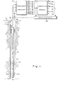
- FIG. 1 there is shown a representative embodiment of an apparatus in accordance with the present invention for investigating subsurface formations 31 traversed by a borehole 32.
- the borehole 32 is typically filled with a drilling fluid or mud which contains finely divided solids in suspension.
- the investigating apparatus or logging device 40 is suspended in the borehole 32 on an armored cable 33, the length of which substantially determines the depth of the device 40.
- the cable length is controlled by suitable means at the surface such as a drum and winch mechanism (not shown).
- Circuitry 51 shown at the surface, although portions thereof may typically be downhole, represents processing circuitry for the various logging units of apparatus 40.
- the investigating apparatus 40 includes a suitable shallow investigation resistivity-determining device such as a microresistivity device 41, which may be of the type described in U.S. Patent No. 3,760,260.
- the device 41 may include skid sidewall 41a which takes measurements used to determine the conductivity axe (or resistivity R xo ), of the formation invaded zone.
- the downhole investigating apparatus also includes a neutron exploring device 42 which may be, for example, of the type disclosed, in U.S. Patent No. 3,483,376.
- the neutron count is received by a processing circuit in the overall circuitry 51 which includes a function former that operates in well known manner to produce a signal ⁇ N which represents the formation porosity as determined by the neutron logging device.
- the investigating apparatus 40 further includes a formation density exploring device 43 for producing well logging measurements which can be utilized to calculate the density of the adjoining formations, in known manner.
- a skid 43A houses a source and two detectors (not shown) spaced different distances from the source.
- the circuitry 51 includes conventional circuits which convert the signals derived from the short and long spacing detectors to a computed density. The resulting density is applied to porosity computing circuitry within the block 51 which computes the porosity, as derived from the bulk density, in well known fashion. The derived porosity is designated as ⁇ D .
- the circuitry 51 also includes a porosity computing circuit which is responsive to ⁇ N and ⁇ D to produce a signal generally known as ⁇ ND that incorporates information from both the neutron and density log readings to obtain an indication of formation total porosity, designated ⁇ t .
- the water-filled porosity ⁇ w of the formations is obtained, and can then be utilized to obtain an indication of water saturation from equation (2).
- the investigating apparatus includes a further device 44 which is a gamma ray logging device for measuring the natural radioactivity of the formations.
- the device 44 may typically include a detector, for example a gamma ray counter, which measures the gamma radiation originating in the formations adjacent the detector.
- An output of circuitry 51 is a signal designated "GR" which represents the gamma ray log reading. If necessary and desired, a clay correction can be applied in the present invention, using the gamma ray log reading.
- An electromagnetic propagation tool (“EPT") 46 is provided, and includes a pad member 46A that has transmitting and receiving antennas therein. Microwave electromagnetic energy is transmitted through the formations (typically the invaded zone) and formation characteristics are determined by measuring the travel time and attenuation of received energy.
- This type of logging tool is described in U.S. Patent No, 3,944,910. Measurements indicative of attenuation, designated ATT, and of travel time (corresponding to phase) designated tp l , are available from this tool. The manner in which these measurements can be used to derive formation parameters is described, for example, in "Electromagnetic Propagation Logging: Advances In Technique And Interpretation", by R. Wharton et al., SPE 9267.
- the dielectric permittivity and conductivity of the formation (generally the invaded zone), as determined from the EPT device, and designated ⁇ EPT and 6 EPT , respectively, can be obtained from where the attenuation has been previously corrected for spread loss.
- the processing circuitry for developing these logged values is contained within the processing circuitry 51, and EEPT and ⁇ EPT are indicated as outputs thereof.
- extendable wall-engaging members 43B and 46B may be provided opposite the members 43A and 46A.
- centralizers 49 may also be provided. It will be understood that various alternative means can be provided for arranging, configuring, and mounting the devices shown, or similar devices.
- the signal outputs of block 51 are illustrated in FIG. 1 as being available to computing module 500 which, in the present embodiment, is implemented by a general purpose digital computer, such as a model PDP-11 sold by Digital Equipment Corp. It will be understood, however, that a suitable special purpose digital or analog computer could alternatively be employed.
- the outputs of the computing module 500, illustrated in FIG. 1, are signal values developed in accordance with techniques described hereinbelow. These signals are recorded as a function of depth on recorder 90, which generically represents graphical, electrical and other conventional storage techniques.
- the measurements to be used in practising the invention are shown, for ease of explanation in the illustrative embodiments, as being derived from a single exploring device, it will be understood that these measurements could typically be derived from a plurality of exploring devices which are passed through the borehole at different times.
- the data from each run can be stored, such as on magnetic storage media, for subsequent processing consistent with the principles of the invention.
- the data may be derived from a remote location, such as by transmission therefrom.
- the rock matrix is assumed to comprise two types, of grains; i.e. spherical grains and platey grains.
- the infinitestimal amounts of grains added to water at each step include both spherical grains and platey grains, which are ellipsoids of revolution in this model, with a fixed aspect ratio (i.e., ratio of length to width).
- the grains are assumed to be uniformly distributed in orientation, so the model is isotropic.
- the bimodal model has two geometrical parameters; the fraction p of the matrix which is platey grains, and the particle depolarization ratio, L which describes the electrical effect of the particle aspect ratio.
- FIG. 2 A simplified pictorial representation of the bimodal model geometry used in the embodiments hereof is shown in FIG. 2.
- the black circles and ovals represent grains, and the white space represents water.
- Each size of particle represents one step in the iterated-dilute-limit method.
- a 3-step approximation i.e., 3 particle sizes
- each particle size is considered to see the effective medium resulting from the previous steps, rather than the actual particles involved in those steps. This effective medium approximation is valid if the particles added at each step are much larger than those of the preceding step.
- FIG. 3 there are shown curves, based on the bimodal model of the relationship (18), of dielectric permittivity vs. frequency and conductivity vs. frequency for a water-filled rock sample from a carbonate that is primarily calcite.
- the rock sample used had a water-filled porosity, ⁇ w , of 0.3, a matrix dielectric permittivity ⁇ m of 7.4, a water conductivity ⁇ w of 1.07 ohm-meters, and a water dielectric permittivity ⁇ w of 78.
- the dielectric permittivity e' and the conductivity a of the composite rock were measured.
- the dielectric measurements of the FIG. 3 example were made, at room temperature, by measuring the reflection and transmission characteristics of the sample in a sample cell using a network analyzer (see M.S. Freedman et al., J. Phys. E:Sci. Inst. 12,899, (1979)).
- the sample cell consisted of a section of coaxial waveguide in which the rock sample constituted the dielectric medium between inner and outer conductors of the waveguide. Teflon plugs at each end of the sample were used as seals to contain the water content in the sample.
- the dielectric constant and conductivity of the sample were computed using both forward and reverse scattering parameters.
- FIG. 4 is another diagram which shows measured values of dielectric permittivity, ⁇ ', and conductivity, a/a w in this case, for a carbonate rock which is primarily dolomite.
- ⁇ w was 0.13
- ⁇ m was 6.8
- ⁇ w was 47
- ⁇ w was 19.6 ohm-meters.
- a relatively high salinity was used to minimize che fractional contribution of surface conductivity effects, such as polarization of a double layer around charged particles such as clays, when present.
- the measurements were made in a manner similar to that described in conjunction with FIG. 3, and the solid line curves were also generated from the bimodal model in the manner previously described. It will be recalled that the solid line curves of FIG.
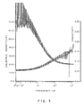
- FIG. 5 illustrates the dependence on frequency of the method used in obtaining the bimodal model curves of FIG. 4. Curves are shown for four different carbonate (primarily dolomite) rock samples in this FIGURE, identified as sample numbers 3, 4, 5 and 7. In this particular example, measurements were made at 151 different frequencies for each sample. Accordingly, the so-called "quality of fit" scale on the vertical axis of FIG. 5 goes up to a maximum value of 151. The plot shows the number of measurement frequencies at which the model value of dielectric permittivity fit inside the error bars.
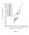
- FIG. 6 illustrates the values of the platey grain fraction p and the depolarization complement 6 at the local maxima of the "quality of fit" curves (e.g. FIG. 5) for ten carbonate rock samples identified as sample numbers 1 through 13A (sample 10 had been utilized in the FIG. 4 example). Each sample had two or more local maxima, which are connected by solid lines. The length of the horizontal bar associated with each point is indicative of the fitting frequency (a wider bar indicating a higher frequency). The height of the vertical bar associated with each point is indicative of the relative value of the "quality of fit" (a taller bar indicating a better fit). Sample 1 produced an anomolous result, with the largest maximum off the page for the scale shown. Platey grain fractions p of about .08 and depolarization complements ⁇ of about .05 are representative.
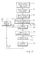
- FIG. 7 there is shown a flow diagram of a routine for determining the water-filled porosity, ⁇ w , and ather properties, of the formations using a form of the invention.
- the routine of FIG. 7 operates as follows: The dielectric permittivity and conductivity from the "EPT" logging device are read in. Parameters representative of rock texture, i.e., p and 6, are selected, e.g., by using representative values from a plot such as FIG. 6.
- the "EPT" logging device is generally operative to obtain measurements on the formation invaded zone, and certain characteristics of the invaded zone, such as the dielectric permittivity of the invading fluid, ⁇ l w , and the conductivity of the invading fluid, a w , are known with fairly good accuracy. Also, the matrix dielectric permittivity, ⁇ m , is known with some confidence, and the operating angular frequency, w , is, of course, known. Accordingly, relationship (18) can be solved to obtain the water-filled porosity, ⁇ w .
- the bimodal model relationship (18) can be used to obtain "reconstructed” or “quality check” values of the formation (invaded zone) conductivity, at the EPT frequency (designated EPT ) and at low (which includes D.C.) frequency (designated a xo ). These reconstructed values can then be utilized for comparison with measured values. If desired, the bimodal model textural parameters can then be modified and the procedure continued until the reconstructed values are sufficiently close to the measured values; whereupon a revised ⁇ w is obtained and recorded.
- the block 711 represents the reading in of logged values for ⁇ EPT and ⁇ EPT from processing circuitry 51.
- ⁇ EPT is shown parenthetically in the block since, in this embodiment, ⁇ EPT is not originally input as a logged value, but is allowed to vary.
- the measured value ⁇ EPT is used as the standard of comparison in the quality check portion of the routine.
- values for the dielectric permittivity and the conductivity of the formations are obtained from the "EPT" device 46 log readings in accordance with the relationships (4) and (5) above.
- the block 713 is next entered, this block representing the imputting of fixed values for the dielectric permittivity of the matrix (grain) material, ⁇ m , the conductivity and dielectric permittivity of the fluid (which, for the invaded zone may be,the values for the invading fluid), ⁇ w and ⁇ l w , respectively, and the angular frequency, ⁇ , of the logging device.
- the logging device used is the "EPT" device 46 of FIG. 1, operating at a frequency of 1100 MHz, although it will be understood that other devices and/or frequencies can be employed.
- the block 715 represents the solving of the bimodal model relationship (18) for porosity ⁇ w and "reconstructed" conductivity EPT . From relationship (18) it will be understood that there are two unknowns in the present embodiment; namely, the porosity ⁇ w , and the formation conductivity, ⁇ . Since relationship (18) is complex, it contains an equation for the real part and an equation for the imaginary part, and these can accordingly be solved for the two unknowns. Solution can be implemented, for example, using Newton's method. The values obtained are output to recorder 90. The value of a solved for is EPT , which is utilized as a quality check as against the originally input value of ⁇ EPT (comparison block 720).
- the textural parameters, p and ⁇ can be modified (block 730) and the loop 750 can be iteratively continued until EPT approaches ⁇ EPT whereupon a modified water-filled porosity, # w , can be read out and recorded.
- Another quality check that can be performed in accordance with the present embodiment pertains to the invaded zone conductivity, a xo .
- the determined value of porosity, ⁇ w can be used in conjunction with a cementation value m, that is determined from the textural parameters in accordance with the low frequency bimodal model relationship (19) of the Archie law (13), to obtain a "quality check” or "reconstructed” value of invaded zone conductivity, xo (block 735).
- This value can be compared, for example, against the value of invaded zone conductivity ⁇ xo measured by a low frequency logging device, such as the device 41 of FIG. 1, and read in, as represented by the block 740.
- the comparison can then be used as a basis for modifying the textural parameters, as previously described, (and as represented by block 730), to improve the textural parameters of the bimodal model.
- the loop 755 can then continue until a satisfactory modified porosity value is obtained. It will be understood that none, one, or both quality checks can be employed, as desired, and it will also be understood that the quality check parameters can be used as recorded logged output values, if desired.
- FIG. 8 is a flow diagram of a routine for obtaining, as outputs, the water-filled porosity, ⁇ w , and the textural parameters p and 6 (which,,inter alia, can be utilized to obtain a cementation exponent m).
- the blocks 811 and 812 represent the inputting of logged values of ⁇ EPT , ⁇ EPT and ⁇ xo from the devices 46 and 41 and processing circuitry 51, as previously described. In the present embodiment, however, ⁇ EPT and a xo are utilized directly in the bimodal model, rather than for quality check.
- Input as fixed values in this embodiment, as represented by the block 813, are the matrix (grain) dielectric permittivity, ⁇ m , the conductivity and dielectric permittivity of the invading fluid a w and ⁇ l w , respectively, and the angular frequency w of the "EPT" logging device.
- FIG. 9 is a flow diagram of a routine in accordance with a further embodiment of the invention. This embodiment is similar to that of FIG. 7 except that, in this case, the conductivity derived from the "EPT" device, ⁇ EPT , is used at a direct input instead of a quality check parameter.
- the block 911 represents the inputting of ⁇ EPT and ⁇ EPT from the processing circuitry 51.
- the textural parameters p and 6 are selected (block 912) as previously described in conjunction with the block 712 of FIG. 7.
- the dielectric permittivity of the matrix, ⁇ m , and ⁇ are input, as represented by block 913.
- the conductivity and dielectric permittivity of the invaded zone fluid, ⁇ w and ⁇ l w , respectively, are not inputs but are obtained from the bimodal model, along with the water-filled porosity, ⁇ w .
- the blocks 935, 940, 960 and 930 operate, in a manner similar to their counterparts 735, 740, 760 and 730, respectively, in FIG. 7, to compute a "reconstructed" xo (block 935), read in the measured axe (block 940), compare the two (block 960), and modify the textural parameters in accordance with the comparison (block 930).
- the loop 955 is continued until the reconstructed xo is sufficiently close to the measured value ⁇ xo ; whereupon revised values of ⁇ w , ⁇ w and ⁇ l w , are obtained and recorded.
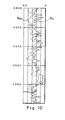
- FIG. 10 illustrates an example of a log of water-filled porosity ⁇ w (shown in solid line) versus depth for a dolomite well.
- a neutron-density crossplot porosity ⁇ ND (shown in dashed line) is shown for comparison. The difference between porosities is due, for the most part, to the presence of residual hydrocarbons in the invaded zone.
- the ⁇ ND values represent total porosity, whereas ⁇ w represents only the water-filled portion of the porosity, under the simplifying assumption that the dielectric permittivity of oil is close to that of the matrix.
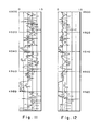
- FIG. 11 shows logs of the reconstructed (generally invaded zone) high frequency conductivity a EPT (dashed line) and the measured ⁇ EPT (solid line), the reconstructed values having been derived using ⁇ EPT measurements and texture values of FIG. 10, and again following the procedure described in conjunction with FIG. 7.
- FIG. 12 shows logs of the reconstructed invaded zone low frequency conductivity xo (dashed line) and the measured ⁇ xo , (solid line), the reconstructed values also having been derived using the procedure described in conjunction with FIG. 7; i.e. using the Archie law, with the ⁇ w values from FIG. 10 and m from the texture values used for FIG. 10.
- the improvements are evident.
- the texture parameters arrived at were used for the zone as a whole. It will be understood that further refinement could be made, for example, through zoning p and 6 from, say, depths 4970 through 4960.
- FIG- 13 the difference between porosities is again attributable, for the most part, to residual hydrocarbon in the well.
- the lower zone below 4980 shows a smaller separation between the two curves, indicating less hydrocarbon is present. This was expected due to water injection into this part of the reservoir.
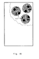
- FIG. 2 had set forth a simplified pictorial representation of the bimodal model geometry.
- FIG.s 16 and 17 show further forms of the bimodal model geometry.
- "chunks" 1610 of the FIG. 2 material i.e. of spherical grains and platey grains of a single aspect ratio, in water, and having the properties described above, which are spheres in this example, are shown as having been added to water.
- ⁇ * chm The complex dielectric permittivity of the composite rock for this "chunk" model, designated ⁇ * chm , can be represented as where ⁇ * ch is the complex dielectric permittivity of the spherical chunk material. Equations can then be developed, and solved, as above, as a function of porosity, electrical parameters, and textural parameters.
- FIG. 17 there is shown a model in which spherical cores of matrix material are "coated” with a mixture of water and platey grains of a single aspect ratio and different sizes.
- the coated grains 1710 are added to water, as before.
- the complex dielectric permittivity of each coated grain, designated ⁇ * cg can be represented as: where V sc is the volume fraction of the sphere coating as a fraction of total grain volume ⁇ * ct is the complex dielectric permittivity of the coating material, and ⁇ * cr is the complex dielectric permittivity of the grain core material.
- the medium in this model is built up by keeping volume of water v w fixed and adding infinitesimal amounts of matrix and hydrocarbon. Defining the volume fraction of matrix grains at an intermediate stage by gives
- the results of the oil-water-matrix with spherical grains is next expanded to include a distribution of spheroidal rock grains and hydrocarbon inclusions i.e., different shapes.
- the iterated dilute limit model is then used as above, in this case by computing the change d ⁇ due to an increase in the concentration dv n of hydrocarbon and dv m of the matrix, using equation (56).
- L m and L n are the values of L for matrix and hydrocarbon respectively.
- v n and v m can have different functional relations.
- m merely reflects the average value of the shape factors of the two non-conducting phases i.e. hydrocarbon and matrix
- m n for the hydrocarbon phase may be more like that corresponding to cigar like or needle like objects, (e.g. prolate spheroids) together with spherical ones, if there are tubular pore throats, in addition to the pore nodes.
- the conductivity can no longer be simply expressed as with m and n as two independent exponents: equation (60) has m depending on S w .
- Equation (62) becomes Next, equation (63) is cast as a sum, as stated above. Pi and ⁇ i can be obtained numerically, and then used in equation (63). Equation (63) can then be solved to obtain ⁇ *.
- FIG. 19 a is plotted vs. frequency.
- ⁇ w is practically frequency independent in this range.
Landscapes
- Life Sciences & Earth Sciences (AREA)
- Physics & Mathematics (AREA)
- General Life Sciences & Earth Sciences (AREA)
- General Physics & Mathematics (AREA)
- Geophysics (AREA)
- Environmental & Geological Engineering (AREA)
- Engineering & Computer Science (AREA)
- Geology (AREA)
- Remote Sensing (AREA)
- Geophysics And Detection Of Objects (AREA)
- Treatment Of Sludge (AREA)
- Investigating Or Analyzing Materials By The Use Of Electric Means (AREA)
- Excavating Of Shafts Or Tunnels (AREA)
Priority Applications (1)
| Application Number | Priority Date | Filing Date | Title |
|---|---|---|---|
| AT85400728T ATE67317T1 (de) | 1984-04-13 | 1985-04-12 | Verfahren und geraet zum erlangen der eigenschaften von unterirdischen lagen. |
Applications Claiming Priority (2)
| Application Number | Priority Date | Filing Date | Title |
|---|---|---|---|
| US06/599,888 US4703277A (en) | 1984-04-13 | 1984-04-13 | Method and apparatus for obtaining properties of subsurface formations from textural models derived from formation parameters |
| US599888 | 1996-02-12 |
Publications (3)
| Publication Number | Publication Date |
|---|---|
| EP0159944A2 true EP0159944A2 (fr) | 1985-10-30 |
| EP0159944A3 EP0159944A3 (en) | 1988-05-18 |
| EP0159944B1 EP0159944B1 (fr) | 1991-09-11 |
Family
ID=24401511
Family Applications (1)
| Application Number | Title | Priority Date | Filing Date |
|---|---|---|---|
| EP85400728A Expired - Lifetime EP0159944B1 (fr) | 1984-04-13 | 1985-04-12 | Procédé et dispositif pour obtenir les propriétés de formations souterraines |
Country Status (5)
| Country | Link |
|---|---|
| US (1) | US4703277A (fr) |
| EP (1) | EP0159944B1 (fr) |
| AT (1) | ATE67317T1 (fr) |
| DE (1) | DE3584030D1 (fr) |
| OA (1) | OA07994A (fr) |
Cited By (2)
| Publication number | Priority date | Publication date | Assignee | Title |
|---|---|---|---|---|
| EP0487424A1 (fr) * | 1990-11-23 | 1992-05-27 | Schlumberger Limited | Procédé et dispositif de diagraphie à haute résolution |
| FR2673238A1 (fr) * | 1991-02-26 | 1992-08-28 | Schlumberger Services Petrol | Procede pour caracteriser les heterogeneites de texture de formations geologiques traversees par un forage. |
Families Citing this family (16)
| Publication number | Priority date | Publication date | Assignee | Title |
|---|---|---|---|---|
| US4786873A (en) * | 1986-06-06 | 1988-11-22 | Amoco Corporation | Method for evaluating water saturation in petroleum reservoirs from dielectric permittivity |
| US5355088A (en) * | 1991-04-16 | 1994-10-11 | Schlumberger Technology Corporation | Method and apparatus for determining parameters of a transition zone of a formation traversed by a wellbore and generating a more accurate output record medium |
| US6060884A (en) * | 1994-03-14 | 2000-05-09 | Meyer, Jr.; Wallace Harold | Method and apparatus for measuring electromagnetic properties of materials in borehole environs and simultaneously determining the quality of the measurements |
| US5892361A (en) * | 1994-03-14 | 1999-04-06 | Baker Hughes Incorporated | Use of raw amplitude and phase in propagation resistivity measurements to measure borehole environmental parameters |
| US5811973A (en) * | 1994-03-14 | 1998-09-22 | Baker Hughes Incorporated | Determination of dielectric properties with propagation resistivity tools using both real and imaginary components of measurements |
| US5502686A (en) * | 1994-08-01 | 1996-03-26 | Western Atlas International | Method and apparatus for imaging a borehole sidewall |
| CA2154378C (fr) | 1994-08-01 | 2006-03-21 | Larry W. Thompson | Methode et appareil de mesure dans un trou de sonde |
| WO1996029616A1 (fr) * | 1995-03-20 | 1996-09-26 | Shell Internationale Research Maatschappij B.V. | Determination d'un parametre d'un constituant d'une composition |
| DE10030602C2 (de) * | 2000-06-21 | 2003-06-18 | Haissam Mouhasseb | Verfahren zur zerstörungsfreien, material-, dichte- und salzunabhängigen sowie temperaturkompensierten Bestimmung der Flüssigwasserkomponente und deren tiefenabhängige ungleichmäßige Verteilung in einem Mehrkomponentengemisch und Vorrichtung zur Durchführung des Verfahrens |
| US6415231B1 (en) | 2000-08-14 | 2002-07-02 | Joel J. Hebert | Method and apparatus for planning and performing a pressure survey |
| US7376514B2 (en) * | 2005-09-12 | 2008-05-20 | Schlumberger Technology Corporation | Method for determining properties of earth formations using dielectric permittivity measurements |
| KR101091807B1 (ko) * | 2011-05-18 | 2011-12-13 | 한국지질자원연구원 | 유전율 센서를 이용한 암석 및 단층점토의 유전율 측정장치 |
| US10605951B2 (en) * | 2014-10-03 | 2020-03-31 | Schlumberger Technology Corporation | Method of determining CEC and other properties from multi-frequency dielectric measurements |
| US10451763B2 (en) * | 2016-10-27 | 2019-10-22 | Schlumberger Technology Corporation | Evaluation of formation utilizing wideband electromagnetic measurements |
| US12104487B2 (en) * | 2020-07-30 | 2024-10-01 | Baker Hughes Oilfield Operations Llc | Determine a formation's textural parameters using advancing logging data |
| WO2022071998A1 (fr) * | 2020-10-02 | 2022-04-07 | Schlumberger Technology Corporation | Procédés et systèmes d'identification de formations à l'aide de rayons gamma naturels liés à une faible quantité d'argile |
Family Cites Families (8)
| Publication number | Priority date | Publication date | Assignee | Title |
|---|---|---|---|---|
| US3081033A (en) * | 1959-01-29 | 1963-03-12 | Petroleum Res Corp | Test unit |
| US3483376A (en) * | 1966-08-03 | 1969-12-09 | Schlumberger Technology Corp | Two neutron detector earth formation porosity logging technique |
| US3590228A (en) * | 1967-10-02 | 1971-06-29 | Schlumberger Technology Corp | Methods and apparatus for processing well logging data |
| US4313164A (en) * | 1971-09-07 | 1982-01-26 | Schlumberger Limited | Method of generating subsurface characteristic models |
| US4340934A (en) * | 1971-09-07 | 1982-07-20 | Schlumberger Technology Corporation | Method of generating subsurface characteristic models |
| US3760260A (en) * | 1972-04-24 | 1973-09-18 | Schlumberger Technology Corp | Method and apparatus for investigating earth formations by emitting survey and auxiliary currents from the same electrode |
| US3944910A (en) * | 1973-08-23 | 1976-03-16 | Schlumberger Technology Corporation | Method and apparatus utilizing microwave electromagnetic energy for investigating earth formations |
| FR2298680A1 (fr) * | 1975-01-24 | 1976-08-20 | Schlumberger Prospection | Procede et dispositif pour mesurer la densite des formations traversees par un forage |
-
1984
- 1984-04-13 US US06/599,888 patent/US4703277A/en not_active Expired - Lifetime
-
1985
- 1985-04-12 AT AT85400728T patent/ATE67317T1/de not_active IP Right Cessation
- 1985-04-12 EP EP85400728A patent/EP0159944B1/fr not_active Expired - Lifetime
- 1985-04-12 OA OA58570A patent/OA07994A/xx unknown
- 1985-04-12 DE DE8585400728T patent/DE3584030D1/de not_active Expired - Lifetime
Cited By (5)
| Publication number | Priority date | Publication date | Assignee | Title |
|---|---|---|---|---|
| EP0487424A1 (fr) * | 1990-11-23 | 1992-05-27 | Schlumberger Limited | Procédé et dispositif de diagraphie à haute résolution |
| FR2669741A1 (fr) * | 1990-11-23 | 1992-05-29 | Schlumberger Services Petrol | Procede et dispositif de diagraphie a haute resolution. |
| FR2673238A1 (fr) * | 1991-02-26 | 1992-08-28 | Schlumberger Services Petrol | Procede pour caracteriser les heterogeneites de texture de formations geologiques traversees par un forage. |
| EP0502757A1 (fr) * | 1991-02-26 | 1992-09-09 | Schlumberger Limited | Procédé pour caractériser les hétérogénéités de texture de formations géologiques traversées par un forage |
| US5809163A (en) * | 1991-02-26 | 1998-09-15 | Schlumberger Technology Corporation | Method of characterizing texture heterogeneities of geological formations traversed by a borehole |
Also Published As
| Publication number | Publication date |
|---|---|
| EP0159944B1 (fr) | 1991-09-11 |
| ATE67317T1 (de) | 1991-09-15 |
| US4703277A (en) | 1987-10-27 |
| EP0159944A3 (en) | 1988-05-18 |
| OA07994A (en) | 1987-01-31 |
| DE3584030D1 (de) | 1991-10-17 |
Similar Documents
| Publication | Publication Date | Title |
|---|---|---|
| EP0159944B1 (fr) | Procédé et dispositif pour obtenir les propriétés de formations souterraines | |
| US10451763B2 (en) | Evaluation of formation utilizing wideband electromagnetic measurements | |
| Tittman | Geophysical well logging: excerpted from methods of experimental physics | |
| Wharton et al. | Electromagnetic propagation logging: Advances in technique and interpretation | |
| US4423323A (en) | Neutron logging method and apparatus for determining a formation characteristic free of environmental effects | |
| US7376514B2 (en) | Method for determining properties of earth formations using dielectric permittivity measurements | |
| EP0159270B1 (fr) | Procédé pour la détermination des propriétés des formations souterraines | |
| US4953399A (en) | Method and apparatus for determining characteristics of clay-bearing formations | |
| US4786873A (en) | Method for evaluating water saturation in petroleum reservoirs from dielectric permittivity | |
| Wharton et al. | Advancements in electromagnetic propagation logging | |
| US4594887A (en) | Method and apparatus for determining characteristics of clay-bearing formations | |
| US4780679A (en) | Method for determining low frequency conductivity of subsurface formations | |
| US4524274A (en) | Methods and apparatus for investigating an earth formation and compensating for borehole environmental effects | |
| Seleznev et al. | Matrix permittivity measurements for rock powders | |
| US11788402B2 (en) | Methods for determining a volume fraction of water and water salinity in organic shale reservoirs using multi-frequency dielectric well logging measurements | |
| US4756189A (en) | Method and apparatus for determining characteristics of clay-bearing formations | |
| US4622849A (en) | Method and apparatus for determining characteristics of clay-bearing formations | |
| Kadhim et al. | Correlation between cementation factor and carbonate reservoir rock properties | |
| Timur | Advances in well logging | |
| McCoy et al. | Use of resistivity logs to calculate water saturation at Prudhoe bay | |
| Safinya et al. | Experimental and theoretical study of the electromagnetic propagation tool in layered and homogeneous media | |
| Timur | Open hole well logging | |
| Cox et al. | Development and testing of the Texaco dielectric log | |
| GB2092783A (en) | Apparatus and Method for Determining Characteristics of Subsurface Formations | |
| McGill | Ground penetrating radar investigations with applications for southern Arizona |
Legal Events
| Date | Code | Title | Description |
|---|---|---|---|
| PUAI | Public reference made under article 153(3) epc to a published international application that has entered the european phase |
Free format text: ORIGINAL CODE: 0009012 |
|
| AK | Designated contracting states |
Designated state(s): AT DE FR GB IT NL |
|
| PUAL | Search report despatched |
Free format text: ORIGINAL CODE: 0009013 |
|
| AK | Designated contracting states |
Kind code of ref document: A3 Designated state(s): AT DE FR GB IT NL |
|
| 17P | Request for examination filed |
Effective date: 19881027 |
|
| 17Q | First examination report despatched |
Effective date: 19891211 |
|
| GRAA | (expected) grant |
Free format text: ORIGINAL CODE: 0009210 |
|
| AK | Designated contracting states |
Kind code of ref document: B1 Designated state(s): AT DE FR GB IT NL |
|
| PG25 | Lapsed in a contracting state [announced via postgrant information from national office to epo] |
Ref country code: IT Free format text: LAPSE BECAUSE OF FAILURE TO SUBMIT A TRANSLATION OF THE DESCRIPTION OR TO PAY THE FEE WITHIN THE PRESCRIBED TIME-LIMIT;WARNING: LAPSES OF ITALIAN PATENTS WITH EFFECTIVE DATE BEFORE 2007 MAY HAVE OCCURRED AT ANY TIME BEFORE 2007. THE CORRECT EFFECTIVE DATE MAY BE DIFFERENT FROM THE ONE RECORDED. Effective date: 19910911 Ref country code: AT Effective date: 19910911 |
|
| REF | Corresponds to: |
Ref document number: 67317 Country of ref document: AT Date of ref document: 19910915 Kind code of ref document: T |
|
| REF | Corresponds to: |
Ref document number: 3584030 Country of ref document: DE Date of ref document: 19911017 |
|
| ET | Fr: translation filed | ||
| PLBE | No opposition filed within time limit |
Free format text: ORIGINAL CODE: 0009261 |
|
| STAA | Information on the status of an ep patent application or granted ep patent |
Free format text: STATUS: NO OPPOSITION FILED WITHIN TIME LIMIT |
|
| 26N | No opposition filed | ||
| PG25 | Lapsed in a contracting state [announced via postgrant information from national office to epo] |
Ref country code: NL Effective date: 19921101 |
|
| NLV4 | Nl: lapsed or anulled due to non-payment of the annual fee | ||
| PG25 | Lapsed in a contracting state [announced via postgrant information from national office to epo] |
Ref country code: FR Effective date: 19921230 |
|
| PG25 | Lapsed in a contracting state [announced via postgrant information from national office to epo] |
Ref country code: DE Effective date: 19930101 |
|
| REG | Reference to a national code |
Ref country code: FR Ref legal event code: ST |
|
| REG | Reference to a national code |
Ref country code: GB Ref legal event code: IF02 |
|
| PGFP | Annual fee paid to national office [announced via postgrant information from national office to epo] |
Ref country code: GB Payment date: 20020410 Year of fee payment: 18 |
|
| PG25 | Lapsed in a contracting state [announced via postgrant information from national office to epo] |
Ref country code: GB Free format text: LAPSE BECAUSE OF NON-PAYMENT OF DUE FEES Effective date: 20030412 |
|
| GBPC | Gb: european patent ceased through non-payment of renewal fee |
Effective date: 20030412 |