EP0160161A1 - Wärmetauscher zum Kühlen von Gasen - Google Patents
Wärmetauscher zum Kühlen von Gasen Download PDFInfo
- Publication number
- EP0160161A1 EP0160161A1 EP85100088A EP85100088A EP0160161A1 EP 0160161 A1 EP0160161 A1 EP 0160161A1 EP 85100088 A EP85100088 A EP 85100088A EP 85100088 A EP85100088 A EP 85100088A EP 0160161 A1 EP0160161 A1 EP 0160161A1
- Authority
- EP
- European Patent Office
- Prior art keywords
- coolant
- tubes
- gas
- tube
- jacket
- Prior art date
- Legal status (The legal status is an assumption and is not a legal conclusion. Google has not performed a legal analysis and makes no representation as to the accuracy of the status listed.)
- Granted
Links
- 239000000112 cooling gas Substances 0.000 title claims description 4
- 239000002826 coolant Substances 0.000 claims abstract description 26
- 239000007789 gas Substances 0.000 claims description 39
- 238000000034 method Methods 0.000 claims description 13
- 238000001816 cooling Methods 0.000 claims description 10
- 239000007788 liquid Substances 0.000 claims description 7
- 238000001704 evaporation Methods 0.000 claims description 5
- 239000000470 constituent Substances 0.000 claims description 4
- 239000004615 ingredient Substances 0.000 claims 1
- 230000015572 biosynthetic process Effects 0.000 description 2
- 239000000203 mixture Substances 0.000 description 2
- 239000002244 precipitate Substances 0.000 description 2
- 229920006395 saturated elastomer Polymers 0.000 description 2
- 239000000571 coke Substances 0.000 description 1
- 238000012544 monitoring process Methods 0.000 description 1
- 239000003507 refrigerant Substances 0.000 description 1
- 238000005496 tempering Methods 0.000 description 1
- XLYOFNOQVPJJNP-UHFFFAOYSA-N water Substances O XLYOFNOQVPJJNP-UHFFFAOYSA-N 0.000 description 1
Images

Classifications
-
- F—MECHANICAL ENGINEERING; LIGHTING; HEATING; WEAPONS; BLASTING
- F28—HEAT EXCHANGE IN GENERAL
- F28D—HEAT-EXCHANGE APPARATUS, NOT PROVIDED FOR IN ANOTHER SUBCLASS, IN WHICH THE HEAT-EXCHANGE MEDIA DO NOT COME INTO DIRECT CONTACT
- F28D7/00—Heat-exchange apparatus having stationary tubular conduit assemblies for both heat-exchange media, the media being in contact with different sides of a conduit wall
- F28D7/16—Heat-exchange apparatus having stationary tubular conduit assemblies for both heat-exchange media, the media being in contact with different sides of a conduit wall the conduits being arranged in parallel spaced relation
- F28D7/1607—Heat-exchange apparatus having stationary tubular conduit assemblies for both heat-exchange media, the media being in contact with different sides of a conduit wall the conduits being arranged in parallel spaced relation with particular pattern of flow of the heat exchange media, e.g. change of flow direction
-
- B—PERFORMING OPERATIONS; TRANSPORTING
- B01—PHYSICAL OR CHEMICAL PROCESSES OR APPARATUS IN GENERAL
- B01D—SEPARATION
- B01D1/00—Evaporating
- B01D1/06—Evaporators with vertical tubes
- B01D1/10—Evaporators with vertical tubes with long tubes, e.g. Kestner evaporators
-
- F—MECHANICAL ENGINEERING; LIGHTING; HEATING; WEAPONS; BLASTING
- F22—STEAM GENERATION
- F22B—METHODS OF STEAM GENERATION; STEAM BOILERS
- F22B1/00—Methods of steam generation characterised by form of heating method
- F22B1/02—Methods of steam generation characterised by form of heating method by exploitation of the heat content of hot heat carriers
- F22B1/18—Methods of steam generation characterised by form of heating method by exploitation of the heat content of hot heat carriers the heat carrier being a hot gas, e.g. waste gas such as exhaust gas of internal-combustion engines
- F22B1/1884—Hot gas heating tube boilers with one or more heating tubes
-
- F—MECHANICAL ENGINEERING; LIGHTING; HEATING; WEAPONS; BLASTING
- F22—STEAM GENERATION
- F22B—METHODS OF STEAM GENERATION; STEAM BOILERS
- F22B25/00—Water-tube boilers built-up from sets of water tubes with internally-arranged flue tubes, or fire tubes, extending through the water tubes
-
- F—MECHANICAL ENGINEERING; LIGHTING; HEATING; WEAPONS; BLASTING
- F28—HEAT EXCHANGE IN GENERAL
- F28D—HEAT-EXCHANGE APPARATUS, NOT PROVIDED FOR IN ANOTHER SUBCLASS, IN WHICH THE HEAT-EXCHANGE MEDIA DO NOT COME INTO DIRECT CONTACT
- F28D7/00—Heat-exchange apparatus having stationary tubular conduit assemblies for both heat-exchange media, the media being in contact with different sides of a conduit wall
- F28D7/10—Heat-exchange apparatus having stationary tubular conduit assemblies for both heat-exchange media, the media being in contact with different sides of a conduit wall the conduits being arranged one within the other, e.g. concentrically
- F28D7/106—Heat-exchange apparatus having stationary tubular conduit assemblies for both heat-exchange media, the media being in contact with different sides of a conduit wall the conduits being arranged one within the other, e.g. concentrically consisting of two coaxial conduits or modules of two coaxial conduits
-
- F—MECHANICAL ENGINEERING; LIGHTING; HEATING; WEAPONS; BLASTING
- F28—HEAT EXCHANGE IN GENERAL
- F28D—HEAT-EXCHANGE APPARATUS, NOT PROVIDED FOR IN ANOTHER SUBCLASS, IN WHICH THE HEAT-EXCHANGE MEDIA DO NOT COME INTO DIRECT CONTACT
- F28D21/00—Heat-exchange apparatus not covered by any of the groups F28D1/00 - F28D20/00
- F28D2021/0019—Other heat exchangers for particular applications; Heat exchange systems not otherwise provided for
- F28D2021/0075—Other heat exchangers for particular applications; Heat exchange systems not otherwise provided for for syngas or cracked gas cooling systems
Definitions
- the invention relates to a method for cooling gases with constituents that tend to cake during the cooling process by heat exchange with an evaporating coolant and an intermediate carrier medium guided in annular spaces between the gases and the coolant, the annular spaces being formed by double tubes which are located within a the jacket containing coolant are arranged and on a heat exchanger in particular for performing such a method.
- the gases to be cooled of the type mentioned above separate their constituents, which liquefy or solidify during the cooling process, on the cooling surfaces.
- the gas-side surface temperature of the pipes is close to the evaporating temperature of the cooling medium, i. H. it is relatively low.
- the resulting deposits of the separated components of the gas become very strong after a short period of operation, significantly deteriorate the heat transfer and cause an increase in the pressure loss of the gas.
- a heat exchanger is known in which the generic method can be carried out.
- the disadvantages mentioned are avoided by introducing a colder, admixture-free, so-called tempering gas into the annular spaces formed by the gas passage tubes and the coolant tubes and mixing them with the gas to be cooled by vortex formation.
- This heat exchanger requires that Provision of a specially cooled, admixture-free temperature control gas. It also results that the correct mixture of gas and temperature control gas is difficult to achieve and control in operational terms and requires an increased technical outlay and that the amount of gas increases by the amount of temperature control gas.
- DE-OS 31 36 860 describes a heat exchanger for cooling hot gases with constituents which precipitate during the cooling process and which has double tubes and coolant collecting chambers formed between two tube plates. Water is passed through the annular spaces of the double pipes, so that, for example, coke forms on the inner wall of the pipes carrying the gas due to the prevailing surface temperatures. From time to time, these precipitates are removed mechanically or by incineration.
- the double tubes are arranged within an open jacket that contains no coolant.
- the invention has for its object to improve the known method and the known heat exchanger for cooling gases with components that tend to caking during the cooling process in such a way that with considerably less technical effort and without the need to provide a special temperature gas as well as monitoring and Regulation of its mixture with the gas to be cooled, the disadvantages and difficulties mentioned above can be avoided.
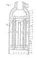
- the tube bundle heat exchanger with a vertical arrangement of the tubes has an upper tube plate 1 and a lower tube plate 2, into which gas passage tubes 3 open.
- the gas to be cooled flows from a gas inlet chamber 15 in the direction of the arrows through the gas passage pipes 3 into a gas outlet chamber 4.
- a connecting chamber 5 or 6 is formed, which on the one hand by the respective tube sheet 2 or 1 and is delimited by a further tube sheet 7 or 8 arranged at a distance from them.
- the coolant tubes 9 are located in a jacket space 11 which is delimited by a jacket 10.
- the jacket 10 stands on the tube sheet 7, is sealed against it and ends at the tube sheet 8.
- the jacket 10 has an inlet connector 12 for a liquid coolant and an outlet 14.
- a passage tube 13 projects into the jacket space 11 and connects the jacket space 11 to the lower connecting chamber 5.
- one end of the passage tube 13 is inserted into the lower tube sheet 7.
- the opening at the other end of the passage tube 13 is located below the tube plate 8 delimiting the upper connecting chamber 6.
- a liquid level 16 is maintained within the jacket space 11, which is below the upper opening of the passage tube 13.
- the liquid cooling medium introduced is heated and the saturated steam generated flows in the direction of the drawing arrows up.
- the saturated steam is then guided downward into the connecting chamber 5 in the through-pipe 13 and flows out of the latter into the connecting chamber 6 and from there into the outlet 14, which here encloses the gas outlet chamber 4 in the form of an annular jacket space. Since the steam absorbs heat from the hot gas to be cooled as it flows through the ring cross sections within the coolant tubes 9, it gets into an overheated state.
- the outlet temperature of the steam can be determined. It is possible to monitor the level of the liquid in the jacket space 11 by means of a control device (not shown) or to regulate it in the sense of the above control option.
Landscapes
- Engineering & Computer Science (AREA)
- Physics & Mathematics (AREA)
- Thermal Sciences (AREA)
- Mechanical Engineering (AREA)
- General Engineering & Computer Science (AREA)
- Chemical & Material Sciences (AREA)
- Chemical Kinetics & Catalysis (AREA)
- Combustion & Propulsion (AREA)
- Life Sciences & Earth Sciences (AREA)
- Sustainable Development (AREA)
- Sustainable Energy (AREA)
- Heat-Exchange Devices With Radiators And Conduit Assemblies (AREA)
Abstract
Description
- Die Erfindung bezieht sich auf ein Verfahren zum Kühlen von Gasen mit während des Kühlvorganges zu Anbackungen neigenden Bestandteilen durch Wärmetausch mit einem verdampfenden Kühlmittel und einem in Ringräumen zwischen den Gasen und dem Kühlmittel geführten Zwischenträgermedium, wobei die Ringräume durch Doppelrohre gebildet sind, die innerhalb eines, das Kühlmittel enthaltenden Mantelraumes angeordnet sind und auf einen Wärmetauscher insbesondere zur Durchführung eines solchen Verfahrens.
- Die zu kühlenden Gase der oben erwähnten Art sondern ihre Bestandteile, die sich während des Kühlvorgangs verflüssigen oder verfestigen, an den Kühlflächen ab. Dabei sind diese Abscheidungen umso stärker je niedriger die Temperatur der Kühlfläche im Verhältnis zur Temperatur des Gases ist. Erfolgt die Kühlung des Gases in Rohren, die von einem Kühlmittel umströmt werden, das um die Rohre herum verdampft, dann liegt die gasseitige Oberflächentemperatur der Rohre nahe der Verdampfungstemperatur des kühlenden Mediums, d. h. sie ist relativ niedrig. Die entstehenden Ablagerungen der ausgeschiedenen Bestandteile des Gases werden dabei schon nach kurzer Betriebszeit sehr stark, verschlechtern den Wärmedurchgang erheblich und bewirken einen Anstieg des Druckverlustes des Gases.
- Aus der DE-PS 29 33 748 ist ein Wärmetauscher bekannt, in dem das gattungsgemäße Verfahren durchgeführt werden kann. Bei diesem Wärmetauscher werden die genannten Nachteile dadurch vermieden, daß in die von den Gasdurchgangsrohren und den Kühlmittelrohren gebildeten Ringräume ein kälteres, beimischungsfreies sogenanntes Temperiergas eingeleitet und durch Wirbelbildung mit dem zu kühlenden Gas vermischt wird. Dieser Wärmetauscher erfordert die Bereitstellung eines besonders gekühlten, beimischungsfreien Temperiergases. Außerdem ergibt sich, daß die richtige Mischung von Gas und Temperiergas betriebsmäßig schwierig zu erreichen und zu steuern ist und einen erhöhten technischen Bauaufwand erfordert und daß sich die Menge des Gases um die Menge des Temperiergases erhöht.
- In der DE-OS 31 36 860 ist-ein Wärmetauscher zur Abkühlung von heißen Gasen mit sich während des Kühlvorganges niederschlagenden Bestandteilen beschrieben, der Doppelrohre und zwischen zwei Rohrböden gebildete Kühlmittelsammelkammern aufweist. Durch die Ringräume der Doppelrohre wird Wasser geführt, so daß sich aufgrund der herrschenden Oberflächentemperaturen an der Innenwand der das Gas führenden Rohre Niederschläge zum Beispiel aus Koks bilden. Diese Niederschläge werden von Zeit zu Zeit mechanisch oder durch Verbrennen entfernt. Die Doppelrohre sind innerhalb eines offenen, kein Kühlmittel enthaltenden Mantels angeordnet.
- Der Erfindung liegt die Aufgabe zugrunde, das bekannte Verfahren und den bekannten Wärmetauscher zum Kühlen von Gasen mit während des Kühlvorganges zu Anbackungen neigenden Bestandteilen so zu verbessern, daß mit einem erheblich geringeren technischen Aufwand und ohne die Notwendigkeit der Bereitstellung eines besonderen Temperiergases sowie der Überwachung und Regelung von dessen Mischung mit dem zu kühlenden Gas, die anfangs erwähnten Nachteile und Schwierigkeiten vermieden werden.
- Diese Aufgabe wird bei einem gattungsgemäßen Verfahren erfindungsgemäß dadurch gelöst, daß das Kühlmittel in dem Mantelraum durch Wärmetausch mit den Gasen verdampft wird und daß der entstandene Dampf als Zwischenträgermedium durch die Ringräume geführt wird. Bei einem insbesondere zur Durchführung eines solchen Verfahrens dienenden Wärmetauscher begrenzen der Mantel und die den Kühlmittelrohren zugeordneten Rohrböden einen Mantelraum, in den ein Einführungsstutzen für die Zufuhr eines verdampfenden Kühlmittels mündet, wobei innerhalb des Mantelraumes ein oder mehrere Durchtrittsrohre vorgesehen sind, deren Eintrittsöffnungen sich oberhalb des in dem Mantelraum eingehaltenen Flüssigkeitsstandes befinden und deren Austrittsöffnungen in die untere Verbindungskammer münden.
- Mit den oben aufgeführten Mitteln lassen sich verhältnismäßig hohe gasseitige Oberflächentemperaturen erreichen und damit das Entstehen der Ablagerungen auf den Rohrwänden ebenfalls vermeiden oder vergleichsweise erheblich verringern.
- Ein Ausführungsbeispiel der Erfindung ist in der Zeichnung dargestellt und wird im folgenden näher erläutert. Es zeigen:
- Fig. 1 den Längsschnitt durch einen Rohrbündelwärmetauscher gemäß der Erfindung und
- Fig. 2 den Schnitt II - II nach Fig. 1.
- Der Rohrbündelwärmeaustauscher mit Vertikalanordnung der Rohre weist einen oberen Rohrboden 1 und einen unteren Rohrboden 2 auf, in die Gasdurchgangsrohre 3 münden. Bei dem dargestellten Ausführungsbeispiel strömt das zu kühlende Gas aus einer Gaseintrittskammer 15 in Richtung der gezeichneten Pfeile durch die Gasdurchtrittsrohre 3 in eine Gasaustrittskammer 4. Oberhalb der Gaseintrittskammer 15 und unterhalb.der Gasaustrittskammer 4 wird jeweils eine verbindungskammer 5 bzw. 6 gebildet, die einerseits von dem jeweiligen Rohrboden 2 bzw. 1 und von einem, im Abstand von diesen angeordneten weiteren Rohrboden 7 bzw. 8 begrenzt wird. In diesen beiden Rohrböden 7 und 8 münden Kühlmittelrohre 9, die die Gasdurchgangsrohre 3 mit Abstand umschließen. Die Kühlmittelrohre 9 befinden sich in einem Mantelraum 11, der von einem Mantel 10 umgrenzt ist. Der Mantel 10 steht auf dem Rohrboden 7 auf, ist gegen diesen abgedichtet und endet am Rohrboden 8. Der Mantel 10 weist einen Einführstutzen 12 für ein flüssiges Kühlmittel und einen Auslaß 14 auf.
- In den Mantelraum 11 ragt ein Durchtrittsrohr 13 hinein, das den Mantelraum 11 mit der unteren Verbindungskammer 5 verbindet. Zu diesem Zweck ist das eine Ende des Durchtrittsrohres 13 in den unteren Rohrboden 7 eingesetzt . Die öffnung an dem anderen Ende des Durchtrittsrohres 13 befindet sich unterhalb des die obere Verbindungskammer 6 begrenzenden Rohrbodens 8. Innerhalb des Mantelraumes 11 ist ein Flüssigkeitsstand 16 eingehalten, der unterhalb der oberen öffnung des Durchtrittsrohres 13 liegt.
- In dem vom Mantel 10 umschlossenen Mantelraum 11 wird das eingeführte flüssige Kühlmedium erhitzt und der erzeugte Sattdampf strömt in Richtung der eingezeichneten Pfeile nach oben. Anschließend wird der Sattdampf in dem Durchtrittsrohr 13 nach unten in die Verbindungskammer 5 geführt und strömt aus dieser nach oben in die Verbindungskammer 6 und von dieser in den Auslaß 14, der hier in Form eines Ringmantelraumes die Gasaustrittskammer 4 umschließt. Da der Dampf beim Strömen durch die Ringquerschnitte innerhalb der Kühlmittelrohre 9 Wärme vom heißen, zu kühlenden Gas aufnimmt, gerät er in einen überhitzten Zustand. Je nach der Ausführung und Bemessung der die Wärme austauschenden Flächen sowie der Höhe des Flüssigkeitsstandes 16 in dem Mantelraum 11 kann die Austrittstemperatur des Dampfes festgelegt werden. Es besteht dabei die Möglichkeit, die Höhe der Flüssigkeit im Mantelraum 11 durch eine (nicht dargestellte) Regeleinrichtung zu überwachen bzw. im Sinne der obenstehenden Steuermöglichkeit zu regeln.
Claims (4)
Applications Claiming Priority (2)
| Application Number | Priority Date | Filing Date | Title |
|---|---|---|---|
| DE19843411795 DE3411795A1 (de) | 1984-03-30 | 1984-03-30 | Verfahren zum betreiben von rohrbuendelwaermeaustauschern zum kuehlen von gasen |
| DE3411795 | 1984-03-30 |
Publications (2)
| Publication Number | Publication Date |
|---|---|
| EP0160161A1 true EP0160161A1 (de) | 1985-11-06 |
| EP0160161B1 EP0160161B1 (de) | 1987-10-21 |
Family
ID=6232083
Family Applications (1)
| Application Number | Title | Priority Date | Filing Date |
|---|---|---|---|
| EP85100088A Expired EP0160161B1 (de) | 1984-03-30 | 1985-01-05 | Wärmetauscher zum Kühlen von Gasen |
Country Status (5)
| Country | Link |
|---|---|
| US (1) | US4589473A (de) |
| EP (1) | EP0160161B1 (de) |
| JP (1) | JPS60207894A (de) |
| CA (1) | CA1244402A (de) |
| DE (2) | DE3411795A1 (de) |
Cited By (1)
| Publication number | Priority date | Publication date | Assignee | Title |
|---|---|---|---|---|
| BE1022816B1 (nl) * | 2015-09-03 | 2016-09-13 | Smo Bvba | Warmtewisselaar en werkwijze voor het genereren van stoom |
Families Citing this family (20)
| Publication number | Priority date | Publication date | Assignee | Title |
|---|---|---|---|---|
| DE3715713C1 (de) * | 1987-05-12 | 1988-07-21 | Borsig Gmbh | Waermetauscher insbesondere zum Kuehlen von Spaltgasen |
| DE3715712C1 (de) * | 1987-05-12 | 1988-07-21 | Borsig Gmbh | Waermetauscher insbesondere zum Kuehlen von Spaltgas |
| US5425415A (en) * | 1993-06-15 | 1995-06-20 | Abb Lummus Crest Inc. | Vertical heat exchanger |
| DE4335711C1 (de) * | 1993-10-20 | 1994-11-24 | Schmidt Sche Heissdampf | Verfahren zur thermischen Entkokung eines Spaltofens und des nachgeschalteten Spaltgaskühlers |
| DE4445687A1 (de) * | 1994-12-21 | 1996-06-27 | Borsig Babcock Ag | Wärmetauscher zum Kühlen von Spaltgas |
| US5813453A (en) * | 1996-06-01 | 1998-09-29 | Deutsche Babcock-Borsig Ag | Heat exchanger for cooling cracked gas |
| RU2124039C1 (ru) * | 1998-02-27 | 1998-12-27 | Товарищество с ограниченной ответственностью "Научно-производственная фирма "Пальна" | Способ получения низших олефинов, реактор для пиролиза углеводородов и аппарат для закалки газов пиролиза |
| RU2140608C1 (ru) * | 1998-04-13 | 1999-10-27 | Дмитриев Сергей Михайлович | Прямоточный вертикальный парогенератор |
| RU2145698C1 (ru) * | 1998-04-21 | 2000-02-20 | Опытное конструкторское бюро машиностроения | Кожухотрубный теплообменник |
| DE19848780C1 (de) * | 1998-10-22 | 2000-05-25 | Krauss Maffei Kunststofftech | Homogenisier- und Temperierbehälter |
| DE10062320A1 (de) * | 2000-12-14 | 2002-06-20 | Borsig Gmbh | Abhitzekessel zum Kühlen von heißem Synthesegas |
| JP4601029B2 (ja) * | 2001-02-20 | 2010-12-22 | 東京エレクトロン株式会社 | 半導体処理装置 |
| JP2004525336A (ja) * | 2001-05-17 | 2004-08-19 | シエル・インターナシヨネイル・リサーチ・マーチヤツピイ・ベー・ウイ | 水蒸気加熱装置 |
| RU2301373C1 (ru) * | 2006-02-10 | 2007-06-20 | Фгуп Окб "Гидропресс" | Модуль парогенератора |
| KR101434252B1 (ko) * | 2006-04-12 | 2014-08-27 | 쉘 인터내셔날 리써취 마트샤피지 비.브이. | 고온 가스 냉각 장치 및 냉각 방법 |
| CN101033922B (zh) * | 2007-04-13 | 2010-05-19 | 天津大学 | 管道式微细管换热器 |
| BR112013023706A2 (pt) * | 2011-03-17 | 2016-12-13 | Nestec Sa | sistemas e métodos para troca de calor |
| RU2540207C1 (ru) * | 2014-01-28 | 2015-02-10 | Открытое акционерное общество "Всероссийский научно-исследовательский институт по эксплуатации атомных электростанций" (ОАО "ВНИИАЭС") | Парогенератор |
| CZ201586A3 (cs) * | 2015-02-10 | 2016-08-03 | ENERGOVĂťZKUM, spol. s.r.o. | Modulový obrácený parní generátor pro jaderné energetické zařízení |
| WO2023128805A1 (ru) * | 2021-12-27 | 2023-07-06 | Акционерное Общество "Машиностроительный Завод "Зио-Подольск" | Теплообменный модуль |
Citations (7)
| Publication number | Priority date | Publication date | Assignee | Title |
|---|---|---|---|---|
| US1677795A (en) * | 1927-06-04 | 1928-07-17 | Ernon V Oliver | Boiler for stills |
| US1782435A (en) * | 1926-11-09 | 1930-11-25 | Gen Chemical Corp | Apparatus for cooling fluids |
| FR842710A (fr) * | 1938-02-22 | 1939-06-19 | Methodes D Aeration Scient Et | Perfectionnements aux installations de réfrigération et échangeuraccumulateur amovible |
| US3097630A (en) * | 1961-02-24 | 1963-07-16 | Brice W Kinyon | Steam generator |
| DE1927949A1 (de) * | 1968-06-04 | 1970-01-08 | Combustion Eng | Dampferzeugungs- und -ueberhitzungsvorrichtung,insbesondere fuer mit geschmolzenem Metall,geschmolzenem Metallsalz od.dgl. als Waermeuebertrager arbeitende Kernreaktoren |
| DE3136860A1 (de) * | 1980-09-12 | 1982-04-08 | Mitsubishi Jukogyo K.K. | Abkuehlwaermetauscher |
| EP0065332A1 (de) * | 1981-05-12 | 1982-11-24 | Esmil B.V. | Vorrichtung und Verfahren zur Konzentration einer Flüssigkeit durch Verdampfung |
Family Cites Families (4)
| Publication number | Priority date | Publication date | Assignee | Title |
|---|---|---|---|---|
| AT339636B (de) * | 1971-11-26 | 1977-10-25 | Messer Griesheim Gmbh | Vorrichtung zur kuhlung von flussigen kraftstoffen oder ahnlichen flussigkeiten |
| DE2913748C2 (de) * | 1979-04-03 | 1983-09-29 | Borsig Gmbh, 1000 Berlin | Rohrbündelwärmetauscher zum Kühlen schlackenhaltiger Heißgase der Kohlevergasung |
| JPS6042843B2 (ja) * | 1979-07-30 | 1985-09-25 | 東洋エンジニアリング株式会社 | 廃熱ボイラ− |
| US4488513A (en) * | 1983-08-29 | 1984-12-18 | Texaco Development Corp. | Gas cooler for production of superheated steam |
-
1984
- 1984-03-30 DE DE19843411795 patent/DE3411795A1/de not_active Ceased
-
1985
- 1985-01-05 DE DE8585100088T patent/DE3560801D1/de not_active Expired
- 1985-01-05 EP EP85100088A patent/EP0160161B1/de not_active Expired
- 1985-01-23 JP JP60010690A patent/JPS60207894A/ja active Pending
- 1985-02-18 CA CA000474544A patent/CA1244402A/en not_active Expired
- 1985-03-11 US US06/710,501 patent/US4589473A/en not_active Expired - Fee Related
Patent Citations (7)
| Publication number | Priority date | Publication date | Assignee | Title |
|---|---|---|---|---|
| US1782435A (en) * | 1926-11-09 | 1930-11-25 | Gen Chemical Corp | Apparatus for cooling fluids |
| US1677795A (en) * | 1927-06-04 | 1928-07-17 | Ernon V Oliver | Boiler for stills |
| FR842710A (fr) * | 1938-02-22 | 1939-06-19 | Methodes D Aeration Scient Et | Perfectionnements aux installations de réfrigération et échangeuraccumulateur amovible |
| US3097630A (en) * | 1961-02-24 | 1963-07-16 | Brice W Kinyon | Steam generator |
| DE1927949A1 (de) * | 1968-06-04 | 1970-01-08 | Combustion Eng | Dampferzeugungs- und -ueberhitzungsvorrichtung,insbesondere fuer mit geschmolzenem Metall,geschmolzenem Metallsalz od.dgl. als Waermeuebertrager arbeitende Kernreaktoren |
| DE3136860A1 (de) * | 1980-09-12 | 1982-04-08 | Mitsubishi Jukogyo K.K. | Abkuehlwaermetauscher |
| EP0065332A1 (de) * | 1981-05-12 | 1982-11-24 | Esmil B.V. | Vorrichtung und Verfahren zur Konzentration einer Flüssigkeit durch Verdampfung |
Cited By (1)
| Publication number | Priority date | Publication date | Assignee | Title |
|---|---|---|---|---|
| BE1022816B1 (nl) * | 2015-09-03 | 2016-09-13 | Smo Bvba | Warmtewisselaar en werkwijze voor het genereren van stoom |
Also Published As
| Publication number | Publication date |
|---|---|
| JPS60207894A (ja) | 1985-10-19 |
| EP0160161B1 (de) | 1987-10-21 |
| CA1244402A (en) | 1988-11-08 |
| US4589473A (en) | 1986-05-20 |
| DE3560801D1 (en) | 1987-11-26 |
| DE3411795A1 (de) | 1985-10-03 |
Similar Documents
| Publication | Publication Date | Title |
|---|---|---|
| EP0160161B1 (de) | Wärmetauscher zum Kühlen von Gasen | |
| DE3039787A1 (de) | Waermeaustauscher | |
| EP0290813B1 (de) | Wärmetauscher, insbesondere zum Kühlen von Spaltgasen | |
| EP0417428A2 (de) | Rohrbündel-Wärmetauscher | |
| DE2008311B2 (de) | Waermetauscher | |
| EP3536763B1 (de) | Quenchsystem und verfahren zum kühlen von spaltgas eines spaltgasofens | |
| DE2512233A1 (de) | Verfahren und vorrichtung zur waermerueckgewinnung aus rauchgasen | |
| DE2109825B2 (de) | Dampferzeuger mit in einem vertikalen Druckbehälter angeordneten Rohrbündel | |
| DE2448832A1 (de) | Fluessigmetall/wasser-waermetauscher mit auswechselbaren rohrbuendeln | |
| DE3043853C2 (de) | Heißgaskühler mit einem Druckbehälter | |
| DE2054578A1 (de) | Mantel und Rohrenwarmeaustauscher zur Dampferzeugung | |
| DE1927949A1 (de) | Dampferzeugungs- und -ueberhitzungsvorrichtung,insbesondere fuer mit geschmolzenem Metall,geschmolzenem Metallsalz od.dgl. als Waermeuebertrager arbeitende Kernreaktoren | |
| DE3039745A1 (de) | Waermeaustauscher | |
| DE2208397A1 (de) | Dampfgenerator | |
| DE3406893C2 (de) | ||
| DE3208467A1 (de) | Konvektionserhitzer zum erhitzen von fluida, wie z.b. eine aufschlaemmung oder dergleichen | |
| DE2753483A1 (de) | Waermetauscher | |
| DE3538515C2 (de) | ||
| DE3121297C2 (de) | Vorrichtung zum Regeln der Temperatur eines korrosiven Gases, insbesondere Synthesegas | |
| DE1619703A1 (de) | Sublimator zur Darstellung eines Reaktionsproduktes durch Desublimation aus einem Gas-Dampf-Gemisch | |
| CH665019A5 (de) | Waermeuebertrager, insbesondere zum kuehlen von gas aus einem hochtemperaturreaktor. | |
| CH665274A5 (de) | Waermeuebertrager. | |
| DE2924460A1 (de) | Vorrichtung zum konzentrieren und/oder reinigen von mineralsaeuren | |
| DE2903644C2 (de) | Wärmetauscher für eine gasgekühlte Kernreaktoranlage | |
| DE2936199C2 (de) | Verfahren zur Überhitzung gasförmiger Medien |
Legal Events
| Date | Code | Title | Description |
|---|---|---|---|
| PUAI | Public reference made under article 153(3) epc to a published international application that has entered the european phase |
Free format text: ORIGINAL CODE: 0009012 |
|
| AK | Designated contracting states |
Designated state(s): DE FR GB IT NL |
|
| 17P | Request for examination filed |
Effective date: 19860405 |
|
| 17Q | First examination report despatched |
Effective date: 19860716 |
|
| GRAA | (expected) grant |
Free format text: ORIGINAL CODE: 0009210 |
|
| AK | Designated contracting states |
Kind code of ref document: B1 Designated state(s): DE FR GB IT NL |
|
| GBT | Gb: translation of ep patent filed (gb section 77(6)(a)/1977) | ||
| REF | Corresponds to: |
Ref document number: 3560801 Country of ref document: DE Date of ref document: 19871126 |
|
| ET | Fr: translation filed | ||
| ITF | It: translation for a ep patent filed | ||
| PLBE | No opposition filed within time limit |
Free format text: ORIGINAL CODE: 0009261 |
|
| STAA | Information on the status of an ep patent application or granted ep patent |
Free format text: STATUS: NO OPPOSITION FILED WITHIN TIME LIMIT |
|
| 26N | No opposition filed | ||
| PGFP | Annual fee paid to national office [announced via postgrant information from national office to epo] |
Ref country code: NL Payment date: 19890131 Year of fee payment: 6 |
|
| PGFP | Annual fee paid to national office [announced via postgrant information from national office to epo] |
Ref country code: FR Payment date: 19891222 Year of fee payment: 6 |
|
| PGFP | Annual fee paid to national office [announced via postgrant information from national office to epo] |
Ref country code: GB Payment date: 19891231 Year of fee payment: 6 |
|
| PG25 | Lapsed in a contracting state [announced via postgrant information from national office to epo] |
Ref country code: GB Effective date: 19910105 |
|
| PG25 | Lapsed in a contracting state [announced via postgrant information from national office to epo] |
Ref country code: NL Effective date: 19910801 |
|
| GBPC | Gb: european patent ceased through non-payment of renewal fee | ||
| NLV4 | Nl: lapsed or anulled due to non-payment of the annual fee | ||
| PG25 | Lapsed in a contracting state [announced via postgrant information from national office to epo] |
Ref country code: FR Effective date: 19910930 |
|
| REG | Reference to a national code |
Ref country code: FR Ref legal event code: ST |
|
| PGFP | Annual fee paid to national office [announced via postgrant information from national office to epo] |
Ref country code: DE Payment date: 19960122 Year of fee payment: 12 |
|
| PG25 | Lapsed in a contracting state [announced via postgrant information from national office to epo] |
Ref country code: DE Effective date: 19971001 |