EP0160227B1 - Dispositif d'affichage électrochromique - Google Patents
Dispositif d'affichage électrochromique Download PDFInfo
- Publication number
- EP0160227B1 EP0160227B1 EP85104003A EP85104003A EP0160227B1 EP 0160227 B1 EP0160227 B1 EP 0160227B1 EP 85104003 A EP85104003 A EP 85104003A EP 85104003 A EP85104003 A EP 85104003A EP 0160227 B1 EP0160227 B1 EP 0160227B1
- Authority
- EP
- European Patent Office
- Prior art keywords
- substrate
- display
- electrode
- holes
- counter
- Prior art date
- Legal status (The legal status is an assumption and is not a legal conclusion. Google has not performed a legal analysis and makes no representation as to the accuracy of the status listed.)
- Expired
Links
Images

Classifications
-
- G—PHYSICS
- G02—OPTICS
- G02F—OPTICAL DEVICES OR ARRANGEMENTS FOR THE CONTROL OF LIGHT BY MODIFICATION OF THE OPTICAL PROPERTIES OF THE MEDIA OF THE ELEMENTS INVOLVED THEREIN; NON-LINEAR OPTICS; FREQUENCY-CHANGING OF LIGHT; OPTICAL LOGIC ELEMENTS; OPTICAL ANALOGUE/DIGITAL CONVERTERS
- G02F1/00—Devices or arrangements for the control of the intensity, colour, phase, polarisation or direction of light arriving from an independent light source, e.g. switching, gating or modulating; Non-linear optics
- G02F1/01—Devices or arrangements for the control of the intensity, colour, phase, polarisation or direction of light arriving from an independent light source, e.g. switching, gating or modulating; Non-linear optics for the control of the intensity, phase, polarisation or colour
- G02F1/15—Devices or arrangements for the control of the intensity, colour, phase, polarisation or direction of light arriving from an independent light source, e.g. switching, gating or modulating; Non-linear optics for the control of the intensity, phase, polarisation or colour based on an electrochromic effect
- G02F1/153—Constructional details
- G02F1/1533—Constructional details structural features not otherwise provided for
-
- G—PHYSICS
- G02—OPTICS
- G02F—OPTICAL DEVICES OR ARRANGEMENTS FOR THE CONTROL OF LIGHT BY MODIFICATION OF THE OPTICAL PROPERTIES OF THE MEDIA OF THE ELEMENTS INVOLVED THEREIN; NON-LINEAR OPTICS; FREQUENCY-CHANGING OF LIGHT; OPTICAL LOGIC ELEMENTS; OPTICAL ANALOGUE/DIGITAL CONVERTERS
- G02F2201/00—Constructional arrangements not provided for in groups G02F1/00 - G02F7/00
- G02F2201/42—Arrangements for providing conduction through an insulating substrate
Definitions
- the present invention relates to an electrochromic display device (hereinafter referred to simply as "ECD") having many display segments. More particularly, the present invention relates to ECD having a number of display segments in the form of dots.
- ECD has merits such as excellent memory characteristics and good contrast in the display, and accordingly has been desired to be employed for various display devices.
- LCD liquid crystal display device
- a great electric current flows instantaneously at the time of driving, and it is necessary to minimize the resistance of the leads connected to the respective segments.
- multiplexing drive is not applicable, and it is required to form one lead for every segment. Accordingly, if the number of segments is increased, the pattern design becomes difficult, and the leads are obliged to be slender and be put around for a increased lead length, whereby the resistance increases, and the response speed of ECD tends to decrease sun- stantially.
- ECD electro-conductive dielectric
- LCD liquid crystal display
- FR-A-2441895 it has been known (FR-A-2441895) to form leads by lamination of electro conductive layers, or to lead out the segments through through-holes to the rear side of a substrate.
- the lamination of electro conductive layers leads to poor productivity, and is hardly applicable particularly in the case where a number of segments are to be provided as in the case of a dot matrix display.
- an electrode formed on one side of a substrate is led out through the substrate to the other side of the substrate.
- Such a method is not useful for ECD, since it is not practical to lead out a display electrode formed on the rear side of a display substrate through the substrate on the front side of the substrate.
- the present invention provides an electrochromic display device which comprises:
- the transparent electrode of the display substrate is led out to the rear side of the facing counter substrate, whereby even if the segments are increased in number, the leading out can readily be made without leading to a drawback of the reduction of the effective display area due to an extended patterning of lead or without an increase of the resistance. Thus, the response speed will not be decreased.
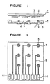
- a display substrate 1 comprises a transparent substrate, a transparent electrode 2 constituting a display electrode formed on the substrate, and a layer 3 of an electrochromic (EC) material such as W0 3 formed on the electrode in a desired pattern.
- EC electrochromic
- the transparent substrate may be of any substrate made of a transparent material such as glass or plastic material and which may contain an ultraviolet absorber or a coloring agent, or which may be provided with an ultraviolet absorbing layer, a colored layer, a non-glare coating layer, a masking layer for non-display portions, a print layer of characters or designs, or a layer of an inorganic or organic substance to prevent the alkali elution to prevent the see- through of the electrode pattern.
- a transparent material such as glass or plastic material and which may contain an ultraviolet absorber or a coloring agent, or which may be provided with an ultraviolet absorbing layer, a colored layer, a non-glare coating layer, a masking layer for non-display portions, a print layer of characters or designs, or a layer of an inorganic or organic substance to prevent the alkali elution to prevent the see- through of the electrode pattern.
- the transparent electrode may be a transparent electrode made of e.g. In 2 0 3 or Sn0 2 . It is usual to employ a colorless transparent electrode. However, in some cases, a colored transparent electrode may be used.
- the electrochromic material may be any substance which reversibly undergoes a color change or can be colored or uncolored (erased) by an application of an electric voltage, such as a transition metal compound, e.g. tungsten oxide, molybdenum oxide or irridium oxide, a viologen compound, or a rare earth metal-diphthalocy- anine compound complex.
- a transition metal compound e.g. tungsten oxide, molybdenum oxide or irridium oxide, a viologen compound, or a rare earth metal-diphthalocy- anine compound complex.
- the electrochromic material may be formed into a layer on the transparent electrode or may be dispersed in the electrolyte. In the present invention, it is preferred to form a transition metal compound in the form of a layer on the transparent electrode.
- the electrochromic material is formed on the transparent electrode in a desired pattern to form a segment.
- a pattern there may be mentioned a 7- segments numerical pattern (letter 8-form), a small dot pattern such as a circle or square as in the case of dot matrix, a designed pattern, or a bar graph pattern.
- the display will be determined by the pattern of the transparent electrode, and any unnecessary portions i.e. a non-display portion may be over-coated with an insulating material.
- the pattern of the transparent electrode is formed larger at least partially than the display pattern so that the transparent electrode is connected to the through-hole of the counter substrate.
- This background material may be any material so long as it is a porous material such as A1 2 0 3 or a fluorine-containing resin which permits the permeation of the ions required to color or uncolor the EC material. It may be a plate-like preformed material or may be formed in the form of a layer on the EC material layer by printing, so long as it is capable of covering the portion beneath the background material.
- the counter substrate 4 has a counter electrode made of e.g. Mn0 2 -carbon or WO x- carbon. When combined with the display substrate 1, the counter substrate 4 permits the disposition of the electrolyte in the space between it and the display substrate. Through-holes 5 are provided on the counter substrate so that the transparent electrodes of the display substrates can be conductively connected through the through-holes 5 to the conductor 8 on the rear side of the counter substrate.
- the counter substrate 4 may be a substrate made of e.g. glass, plastics, ceramics or metals, and may be opaque.
- the counter substrate is provided with a recess 6 by a suitable method such as etching, press molding or sand blasting, and protrusions 7 with the through-holes.
- a preformed spacer may be sandwiched between the display substrate and the counter substrate, so long as the electrolyte can be filled in the space.
- it is preferred to form a recess in a relatively thick substrate so that the thickness of the sealing material may be thin, and the reliability and the production efficiency will be high.
- conductors 8 are provided for external connection.
- transparent electrodes 2 and conductors 8 are conductively connected.
- the size of the through-holes may vary depending upon the size of the segments or the processing precision. However, the through-holes usually have a diameter of from 0.2 to 2 mm and a length of from 0.5 to 3 mm which correponds to the thickness of the counter substrate, which is determined by e.g. the thickness of the electrolyte layer and the strength of the counter substrate.
- the through-holes 5 are slightly enlarged at the rear side of the board to form recesses 9.
- the recesses 9 are provided to facilitate the operation of filling a conductive material into the through-holes.
- the conductive material may be injected into the recesses 9 and the through-holes by means of e.g. an injector.
- the through-holes are relatively narrow, and it is likely that the air remains in the through-holes in the form of air bubbles, whereby after the injection, the ECD cell is placed in a reduced presure container, and vacuumed to remove the air bubbles, and then returned to atmospheric pressure, whereby the conductive material is sucked into the through-holes, and the reliability of the conductive connection is improved.
- the conductive material to be filled in the through-holes may be a paste comprising conductive particles such as silver, copper or carbon particles, and a binder. Otherwise, it may be a metal having a low melting point, such as a solder.
- the conductive material may be filled in the through-holes prior to the assembling of the ECD cell.
- a paste for forming a conductor is supplied from one side of the through-holes while aspirating from the other side under reduced pressure, whereby the paste is cured to form a film of a conductor on the inner walls of the through-holes.
- a non-cured conductive material is applied to the forward ends of the through-holes to connect the transparent electrodes of the display substrate with the conductors on the inner walls of the through-holes.
- Figure 2 is a bottom view illustrating the rear side of the counter substrate of Figure 1, and shows a through-hole 5, a recess 9, a conductor 8 and external lead out terminals 10 and 11.
- the conductor may extend from the periphery of the recess 9 to the external lead out terminal 10, as illustrated by this embodiment, or it may constitute a circuit board whereby a circuit element such as an integrated circuit (IC) is mounted on the rear side of the counter substrate.
- the conductor is formed to have an annular shape or a generally annular shape along the periphery of the recess 9, whereby the reliability of the connection is ensured.
- the material for this conductor may be the same material as the above-mentioned conductive material. It may be a metal material such as a copper foil. Further, if necessary, soldering treatment, nickel plating treatment, or the like may be applied to its surface.
- the terminal 11 is a terminal connected to the counter electrode although such connections is not shown in the drawing.
- the display substrate 1 and the counter substrate 4 are connected, if necessary, with a sealing material, to form a cell.
- sealing material there may be mentioned such materials as glass frits (solder glass), fluorinated resins, epoxy resins or silicone resins, which may be cured e.g. by heating, by radiation with ultraviolet rays or by mixing two liquids.
- glass frits solder glass
- fluorinated resins fluorinated resins
- epoxy resins epoxy resins
- silicone resins which may be cured e.g. by heating, by radiation with ultraviolet rays or by mixing two liquids.
- each protrusion 7 it is preferred to apply the sealing material in an annular shape at the top of each protrusion 7 for secure bonding, whereby the conductive material in the through-hole is prevented from being in direct contact with the electrolyte. Further, since the substrate is bonded thereto, even when exposed to a high temperature and the electrolyte undergoes a volume expansion, the conductive connection is hardly disconnected, whereby high reliability is ensured.
- a conductive material is injected through the through-holes and filled therein to establish the conductive connection, and an electrolyte is filled through an inlet not shown and then the inlet is sealed.
- the conductive connection may be established at the same time as the curing of the sealing material.
- the electrolyte may contain an EC material in itself or it may be capable of coloring and uncoloring (erasing) the EC material or permitting the EC material to undergo a color change.
- the electrolyte may be liquid, gel or solid. In the case of a solid electrolyte, a sealing material is not necessarily required.
- an electrolyte prepared by dissolving a supporting electrolyte such as lithium perchlorate in an organic solvent such as propylene carbonate or y-butylolactone.
- a gel-type electrolyte in which e.g. polyvinyl butyral is dissolved, or a film-type electrolyte prepared by impregnating an electrolyte in a porous film, may also be employed.
- the electrolyte In the case where the electrolyte is liquid, it may be injected from an inlet provided in the cell.
- the interior of the cell may be divided into a plurality of sections, and a plurality of inlets may be provided.
- the inlets may be formed at the side surface of the cell or at the rear surface of the cell.
- the electrolyte In the case where the electrolyte is solid, the solid electrolyte may be laminated on the display substrate or the counter substrate prior to the assembling into a cell.
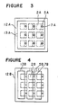
- Figures 3 and 4 are front views of ECD of the present invention.
- Figure 3 illustrates an embodiment wherein the protrusions 7A are formed in the shape of a cylinder
- Figure 4 illustrates an embodiment wherein the protrusions 7B are formed in the shape of a strip.
- the protrusions are provided with through-holes 5A or 5B and connected to the transparent electrodes 2A or 2B as shown by dotted lines.
- an inlet 13A or inlets 13B are provided along the peripheral sealing portion 12A or 12B, and shown by dotted lines.
- the protrusions are in the form of a strip, and a plurality of inlets corresponding to the number of divided chambers are required. In this embodiment, three inlets are provided.
- a number of electrodes can be taken out without dividing the interior of the cell as shown by the embodiment of Figure 3, and in such a case, only one inlet will be sufficient.
- Figure 5 is a cross-sectional view of a part of the assembled cell of the present invention, wherein the display substrate 1 and the counter substrate 4 are sealed along their periphery, and bonded also by the sealing material 14 provided in an annular form at the top of each protrusion 7 with a through-hole 5, and an electrolyte is filled in the interior of the cell.
- a conductive material 15 is filled to connect the transparent electrodes 2 on the display substrate with the conductors 8 on the rear side of the counter substrate.
- a porous plate made of AL 2 0 3 or a fluorinated resin may be inserted between the display substrate and the counter substrate for use as a background plate, or a background plate and a counter electrode may be overlaid on the display electrode.
- non-display portions on the outer surface or inner surface of the display substrate there may be provided letters, designs or mask- ings by printing or vapour disposition.
- the display quality may be improved by providing an opaque masking the non-display portion to cover the portion other than the display electrode so that e.g. the through-holes will not be seen.
- by providing an opaque masking on the outer surface corresponding to the non-display portion by e.g. printing, the through-holes, etc. behind it can be made invisible.
- the through-hole portions visibly blackish can be turned to a visible whitish whereby the aparent whiteness improves, and the color of the colored segments can be clearly seen with an improved contrast.
- ECD of the present invention may be used for e.g. a dot matrix, a bar graph, a character or design display or a 7-segments numerical display. It is particularly effective when used for a dot matrix having a great number of segments, for example, 7 x 5 dots or 9 x 13 dots.
- the present invention is also suitable for a large size ECD wherein, for instance, a single character is displayed by a single ECD, and a word or sentence is displayed by a combination of a plurality of ECDs.
- ITO In 2 0 3 -Sn0 2
- the counter substrate was prepared from a glass plate of the same size by etching it to a depth of 0.8 mm to form a recess and protrusions in correspondence with the above-mentioned dots, and sand-blasting it to form through-holes having a diameter of about 0.5 mm and with slightly larger recesses at the rear side of the substrate.
- W,8049, V 6 0 13 and carbon were used as a counter electrode.
- a lead pattern as shown in Figure 2 was formed with a conductive material paste containing silver particles on the rear side of the counter substrate.
- the counter electrode was also conductively connected through two through-holes to the rear side of the counter substrate.
- the display substrate and the counter substrate thus prepared were heat-sealed along the peripheral sealing portion and at the top portions of the protrusions, with an epoxy-type sealing material.
- a conductive material paste containing silver particles was injected to the through-holes by means of an injector needle; then the assembly was placed in a reduced pressure container and subjected to a reduced pressure to remove air bubbles from the through-holes; and the pressure was returned to atmospheric pressure, whereby the conductive material paste was filled in the through-holes.
- the paste was then cured and conductively connected to the transparent electrode 17.
- propylene carbonate in which lithium perchorate was dissolved was injected through an inlet, and the inlet was then sealed.
- the ECD cell thus obtained had a resistance of about 10 from the through-hole to the terminal, and the time required to obtain a coloring of 6 mC/cm 2 at 1.5 V was from 800 to 1500 msec. If the transparent electrode (about 35 Q/D) of the above display substrate were taken out as a lead, the resistance would be as high as about 350 0 with a length of 10 cm, and the response speed would be at least 10 times. Thus, it is evident that the example of this invention is superior for a large size ECD having a number of segments.
- the counter substrate was prepared from a glass plate of the same size by etching it to a depth of 0.3 mm to form a recess and protrusions in correspondence with the above-mentioned dots, and sand-blasting it to form through-holes having a diameter of 0.5 mm. Then, from the protrusion side, a conductive material paste containing silver particles was printed by means of a screen printing plate having an aperture with a diameter of 0.9 mm, and at the same time, aspiration was applied from the rear side to suck the conductive material paste into the through-holes and apply the paste onto the inner walls of the through-holes. Then, drying was conducted at 80°C for 10 minutes, and a lead pattern as shown in Figure 3 was printed on the rear side of the counter substrate with the same conductive material paste. The temperature was raised to 530°C to fix the pattern.
- the protrusions were masked in an annular shape, and vapour deposition was conducted to form an undercoating for a counter electrode, and at the same time to form annular electrodes on the top portions of the protusions.
- the resistance from the annular electrode on the top portion of the protrusion to the terminal was about 1 O.
- W l .0 49 , V 6 0 13 and carbon were formed into a sheet, and holes were provided to avoid the contact with the protrusions.
- the counter electrode was conductively connected to the undercoat electrode, and the undercoat electrode was conductively connected through two through-holes to the rear side of the counter substrate.
- the display substrate and the counter substrate thus prepared were heat-sealed along the peripheral sealing portion and at the top portions of the protrusions, with an epoxy-type sealing material.
- propylene carbonate in which lithium perchlorate was dissolved was injected through an inlet, and then the inlet was sealed.
- the ECD cell thus obtained had a resistance of about 1 0 from the through-hole to the terminal, and the time required to obtain a coloring of 6 mC/cm 2 at 1.5 V was from 500 to 1000 msec this exhibiting excellent characteristics.
- this embodiment of the present invention is superior in the operation efficiency as well as the display characteristics for a large size ECD having a number of segments.
- a masking was formed on the outer surface of each of the ECD cells of Examples 1 and 2 at portions corresponding to the through-hole portions.
- This masking was formed by printing an ink composition prepared by mixing white, black and green inks for glass in a weight ratio of 300:1:1, respectively and drying the printed ink composition, whereby the masking had a color substantially the same as the color of the uncolored (erased) display portion.
- the display electrode is conductively connected through the through-holes to the rear side of the counter substrate, whereby the lead resistance can be minimized and a reliable electric conduction can be established, and a high response speed is obtainable for ECD having a number of segments.
- the present invention is useful for various applications.
Landscapes
- Physics & Mathematics (AREA)
- Nonlinear Science (AREA)
- General Physics & Mathematics (AREA)
- Optics & Photonics (AREA)
- Devices For Indicating Variable Information By Combining Individual Elements (AREA)
- Electrochromic Elements, Electrophoresis, Or Variable Reflection Or Absorption Elements (AREA)
Claims (8)
Applications Claiming Priority (2)
| Application Number | Priority Date | Filing Date | Title |
|---|---|---|---|
| JP71844/84 | 1984-04-12 | ||
| JP59071844A JPS60216333A (ja) | 1984-04-12 | 1984-04-12 | エレクトロクロミツク表示素子 |
Publications (2)
| Publication Number | Publication Date |
|---|---|
| EP0160227A1 EP0160227A1 (fr) | 1985-11-06 |
| EP0160227B1 true EP0160227B1 (fr) | 1988-07-20 |
Family
ID=13472250
Family Applications (1)
| Application Number | Title | Priority Date | Filing Date |
|---|---|---|---|
| EP85104003A Expired EP0160227B1 (fr) | 1984-04-12 | 1985-04-02 | Dispositif d'affichage électrochromique |
Country Status (4)
| Country | Link |
|---|---|
| US (1) | US4702566A (fr) |
| EP (1) | EP0160227B1 (fr) |
| JP (1) | JPS60216333A (fr) |
| DE (1) | DE3563888D1 (fr) |
Families Citing this family (97)
| Publication number | Priority date | Publication date | Assignee | Title |
|---|---|---|---|---|
| US5007718A (en) * | 1987-04-02 | 1991-04-16 | Kabushiki Kaisha Toyota Chuo Kenkyusho | Electrochromic elements and methods of manufacturing and driving the same |
| US5355245A (en) * | 1988-02-12 | 1994-10-11 | Donnelly Corporation | Ultraviolet protected electrochemichromic rearview mirror |
| JPH01128288U (fr) * | 1988-02-22 | 1989-09-01 | ||
| US4892394A (en) * | 1988-05-03 | 1990-01-09 | Bidabad Farid M | Electronic sun shield |
| JPH03276186A (ja) * | 1990-03-27 | 1991-12-06 | Semiconductor Energy Lab Co Ltd | 表示用基板 |
| US5432015A (en) * | 1992-05-08 | 1995-07-11 | Westaim Technologies, Inc. | Electroluminescent laminate with thick film dielectric |
| DE69426040T2 (de) * | 1993-02-26 | 2001-05-17 | Donnelly Corp., Holland | Elektrochrome polymerische Festfilme, Herstellung elektrochromer Vorrichtungen mit solchen Filmen, und Verfahren zur Herstellung solcher Festfilme und Vorrichtungen |
| US5910854A (en) | 1993-02-26 | 1999-06-08 | Donnelly Corporation | Electrochromic polymeric solid films, manufacturing electrochromic devices using such solid films, and processes for making such solid films and devices |
| US5668663A (en) * | 1994-05-05 | 1997-09-16 | Donnelly Corporation | Electrochromic mirrors and devices |
| US6891563B2 (en) | 1996-05-22 | 2005-05-10 | Donnelly Corporation | Vehicular vision system |
| JP3752010B2 (ja) * | 1995-07-04 | 2006-03-08 | 新日本石油株式会社 | 調光素子 |
| AU4153397A (en) | 1996-08-20 | 1998-03-06 | Donnelly Corporation | Window assembly with controllable optical transmission |
| US5877888A (en) * | 1997-06-10 | 1999-03-02 | Monsanto Company | Single and double sided electrochromic displays |
| US8294975B2 (en) | 1997-08-25 | 2012-10-23 | Donnelly Corporation | Automotive rearview mirror assembly |
| US6124886A (en) | 1997-08-25 | 2000-09-26 | Donnelly Corporation | Modular rearview mirror assembly |
| US6172613B1 (en) | 1998-02-18 | 2001-01-09 | Donnelly Corporation | Rearview mirror assembly incorporating vehicle information display |
| US6326613B1 (en) | 1998-01-07 | 2001-12-04 | Donnelly Corporation | Vehicle interior mirror assembly adapted for containing a rain sensor |
| US6445287B1 (en) | 2000-02-28 | 2002-09-03 | Donnelly Corporation | Tire inflation assistance monitoring system |
| US8288711B2 (en) | 1998-01-07 | 2012-10-16 | Donnelly Corporation | Interior rearview mirror system with forwardly-viewing camera and a control |
| US6477464B2 (en) | 2000-03-09 | 2002-11-05 | Donnelly Corporation | Complete mirror-based global-positioning system (GPS) navigation solution |
| US6693517B2 (en) | 2000-04-21 | 2004-02-17 | Donnelly Corporation | Vehicle mirror assembly communicating wirelessly with vehicle accessories and occupants |
| US6329925B1 (en) | 1999-11-24 | 2001-12-11 | Donnelly Corporation | Rearview mirror assembly with added feature modular display |
| US6317248B1 (en) | 1998-07-02 | 2001-11-13 | Donnelly Corporation | Busbars for electrically powered cells |
| US6597489B1 (en) | 1999-06-30 | 2003-07-22 | Gentex Corporation | Electrode design for electrochromic devices |
| JP4345153B2 (ja) | 1999-09-27 | 2009-10-14 | ソニー株式会社 | 映像表示装置の製造方法 |
| DE10006199B4 (de) * | 2000-02-11 | 2005-05-25 | Schott Ag | Formkörper aus sprödbrüchigem Material |
| US7370983B2 (en) | 2000-03-02 | 2008-05-13 | Donnelly Corporation | Interior mirror assembly with display |
| US7167796B2 (en) | 2000-03-09 | 2007-01-23 | Donnelly Corporation | Vehicle navigation system for use with a telematics system |
| WO2001064481A2 (fr) | 2000-03-02 | 2001-09-07 | Donnelly Corporation | Systeme de miroir video integrant un module accessoire |
| US7195381B2 (en) | 2001-01-23 | 2007-03-27 | Donnelly Corporation | Vehicle interior LED lighting system |
| US6407847B1 (en) | 2000-07-25 | 2002-06-18 | Gentex Corporation | Electrochromic medium having a color stability |
| US7581859B2 (en) | 2005-09-14 | 2009-09-01 | Donnelly Corp. | Display device for exterior rearview mirror |
| US7255451B2 (en) | 2002-09-20 | 2007-08-14 | Donnelly Corporation | Electro-optic mirror cell |
| EP1271227A1 (fr) * | 2001-06-26 | 2003-01-02 | Nanomat Limited | Dispositif d'affichage électrochromique à haute resolution et procédé pour sa production |
| US6918674B2 (en) | 2002-05-03 | 2005-07-19 | Donnelly Corporation | Vehicle rearview mirror system |
| US7329013B2 (en) | 2002-06-06 | 2008-02-12 | Donnelly Corporation | Interior rearview mirror system with compass |
| WO2003105099A1 (fr) | 2002-06-06 | 2003-12-18 | Donnelly Corporation | Systeme de miroir de courtoisie interieur a boussole |
| US7274501B2 (en) | 2002-09-20 | 2007-09-25 | Donnelly Corporation | Mirror reflective element assembly |
| US7310177B2 (en) | 2002-09-20 | 2007-12-18 | Donnelly Corporation | Electro-optic reflective element assembly |
| US7289037B2 (en) | 2003-05-19 | 2007-10-30 | Donnelly Corporation | Mirror assembly for vehicle |
| EP1519220A1 (fr) * | 2003-09-27 | 2005-03-30 | 3M Innovative Properties Company | Dispositif d'affichage électrochimique |
| EP1519212A1 (fr) * | 2003-09-27 | 2005-03-30 | 3M Innovative Properties Company | Dispositif d'affichage permettant la commutation irreversible d'un premier état vers un deuxiéme état |
| US7446924B2 (en) | 2003-10-02 | 2008-11-04 | Donnelly Corporation | Mirror reflective element assembly including electronic component |
| US7308341B2 (en) | 2003-10-14 | 2007-12-11 | Donnelly Corporation | Vehicle communication system |
| US20070121190A1 (en) * | 2003-10-21 | 2007-05-31 | Koninklijke Philips Electronics N.V. | Display |
| KR20060131886A (ko) * | 2004-03-17 | 2006-12-20 | 코닌클리케 필립스 일렉트로닉스 엔.브이. | 디스플레이 패널 |
| US7177064B2 (en) * | 2004-06-11 | 2007-02-13 | Lg Chem, Ltd. | Display device using printed circuit board as substrate of display panel |
| US20060163540A1 (en) * | 2005-01-27 | 2006-07-27 | Chien-Hsin Yang | Solid status electro-chromic device process using conductive polymer nano material |
| EP1883855B1 (fr) | 2005-05-16 | 2011-07-20 | Donnelly Corporation | Ensemble de retroviseur de vehicule comportant des informations sur l'element reflecteur |
| CN101535087B (zh) | 2005-11-01 | 2013-05-15 | 唐纳利公司 | 具有显示装置的内部后视镜 |
| US8038495B2 (en) | 2006-01-20 | 2011-10-18 | Samsung Mobile Display Co., Ltd. | Organic light-emitting display device and manufacturing method of the same |
| KR100673765B1 (ko) | 2006-01-20 | 2007-01-24 | 삼성에스디아이 주식회사 | 유기전계발광 표시장치 및 그 제조방법 |
| KR100635514B1 (ko) * | 2006-01-23 | 2006-10-18 | 삼성에스디아이 주식회사 | 유기전계발광표시장치 및 그 제조방법 |
| JP4624309B2 (ja) * | 2006-01-24 | 2011-02-02 | 三星モバイルディスプレイ株式會社 | 有機電界発光表示装置及びその製造方法 |
| JP4456092B2 (ja) | 2006-01-24 | 2010-04-28 | 三星モバイルディスプレイ株式會社 | 有機電界発光表示装置及びその製造方法 |
| KR100671641B1 (ko) * | 2006-01-25 | 2007-01-19 | 삼성에스디아이 주식회사 | 유기 전계 발광 표시장치 및 그 제조 방법 |
| KR100688795B1 (ko) * | 2006-01-25 | 2007-03-02 | 삼성에스디아이 주식회사 | 유기전계발광 표시장치 및 그 제조방법 |
| US8164257B2 (en) | 2006-01-25 | 2012-04-24 | Samsung Mobile Display Co., Ltd. | Organic light emitting display and method of fabricating the same |
| KR100685853B1 (ko) * | 2006-01-25 | 2007-02-22 | 삼성에스디아이 주식회사 | 유기전계발광표시장치 및 그 제조방법 |
| JP4633674B2 (ja) | 2006-01-26 | 2011-02-16 | 三星モバイルディスプレイ株式會社 | 有機電界発光表示装置及びその製造方法 |
| KR100671647B1 (ko) | 2006-01-26 | 2007-01-19 | 삼성에스디아이 주식회사 | 유기전계발광 표시 장치 |
| KR100732808B1 (ko) * | 2006-01-26 | 2007-06-27 | 삼성에스디아이 주식회사 | 유기전계발광 표시장치의 제조방법 |
| KR100671639B1 (ko) * | 2006-01-27 | 2007-01-19 | 삼성에스디아이 주식회사 | 유기 전계 발광 표시장치 및 그 제조 방법 |
| KR100713987B1 (ko) * | 2006-02-20 | 2007-05-04 | 삼성에스디아이 주식회사 | 기판 밀착장치 및 이를 이용한 유기전계발광 표시장치의밀봉방법 |
| KR100732817B1 (ko) | 2006-03-29 | 2007-06-27 | 삼성에스디아이 주식회사 | 유기전계발광 표시장치 및 그 제조방법 |
| US7990603B2 (en) | 2006-06-09 | 2011-08-02 | Gentex Corporation | Variable transmission window system |
| DE602007012890D1 (de) | 2006-07-28 | 2011-04-14 | Chromogenics Sweden Ab | Kontaktierung von elektrochromen anordnungen |
| WO2009002556A1 (fr) * | 2007-06-27 | 2008-12-31 | Gentex Corporation | Dispositif électrochromique comportant un connecteur de port de charge amélioré |
| US8345345B2 (en) | 2007-06-27 | 2013-01-01 | Gentex Corporation | Electrochromic device having an improved fill port plug |
| US8154418B2 (en) | 2008-03-31 | 2012-04-10 | Magna Mirrors Of America, Inc. | Interior rearview mirror system |
| US7535614B1 (en) | 2008-05-27 | 2009-05-19 | Gentex Corporation | Electrical window control system and method thereof |
| US20110170162A1 (en) * | 2008-09-08 | 2011-07-14 | Ntera, Inc. | Printed display systems based on porous substrates |
| US9487144B2 (en) | 2008-10-16 | 2016-11-08 | Magna Mirrors Of America, Inc. | Interior mirror assembly with display |
| US9405165B2 (en) | 2012-03-30 | 2016-08-02 | Gentex Corporation | Controller configured for an electro-optic device and method thereof |
| US9057925B2 (en) | 2013-03-15 | 2015-06-16 | Gentex Corporation | Fill port plugs for electrochromic devices |
| WO2015051262A1 (fr) | 2013-10-04 | 2015-04-09 | Gentex Corporation | Système de fenêtre à transmittance variable |
| US9454054B2 (en) | 2013-11-18 | 2016-09-27 | Magna Mirrors Of America, Inc. | Electro-optic mirror element and process of making same |
| WO2015077313A1 (fr) | 2013-11-19 | 2015-05-28 | Gentex Corporation | Reduction de la condensation dans des systemes de hublot a intensite lumineuse reglable |
| US9586669B2 (en) | 2013-11-25 | 2017-03-07 | Gentex Corporation | Aerospace protective dust cover |
| WO2015187837A1 (fr) | 2014-06-05 | 2015-12-10 | Gentex Corporation | Ensemble cache antipoussière à lumière périphérique |
| US9694752B2 (en) | 2014-11-07 | 2017-07-04 | Gentex Corporation | Full display mirror actuator |
| US10167073B2 (en) | 2015-06-09 | 2019-01-01 | Gentex Corporation | Multi-piece bezel for electro-optic window assembly |
| WO2016201087A1 (fr) | 2015-06-09 | 2016-12-15 | Gentex Corporation | Retenue d'un ensemble hublot électro-optique |
| EP3359404A4 (fr) | 2015-10-07 | 2018-12-05 | Gentex Corporation | Toit ouvrant comprenant un élément électro-optique |
| WO2017201368A1 (fr) | 2016-05-20 | 2017-11-23 | Gentex Corporation | Système de commande de fenêtre électro-optique |
| WO2018195458A1 (fr) | 2017-04-20 | 2018-10-25 | Cardinal Ig Company | Structures de vitrage de confidentialité haute performance |
| WO2019014613A1 (fr) | 2017-07-13 | 2019-01-17 | Cardinal Ig Company | Configurations de connexion électrique de structures de vitrage opaque |
| WO2019090341A1 (fr) | 2017-11-06 | 2019-05-09 | Cardinal Ig Company | Système de vitrage opaque à conducteur électrique distinct |
| MX2020011871A (es) | 2018-05-09 | 2021-01-20 | Cardinal Ig Co | Acristalamiento de privacidad controlable electricamente con impulsor de recuperacion de energia. |
| WO2020037185A1 (fr) | 2018-08-17 | 2020-02-20 | Cardinal Ig Company | Structure de vitrage opaque dotée de décalages de vitre asymétriques pour configurations de connexion électrique |
| US11474385B1 (en) | 2018-12-02 | 2022-10-18 | Cardinal Ig Company | Electrically controllable privacy glazing with ultralow power consumption comprising a liquid crystal material having a light transmittance that varies in response to application of an electric field |
| WO2020163836A1 (fr) | 2019-02-08 | 2020-08-13 | Cardinal Ig Company | Dispositif d'excitation à faible puissance pour les vitrages d'intimité |
| US11474408B2 (en) * | 2019-03-19 | 2022-10-18 | Ricoh Company, Ltd. | Electronic device, method for producing electronic device, and photochromatic lens unit |
| MX2021013262A (es) | 2019-04-29 | 2022-01-06 | Cardinal Ig Co | Deteccion y control de corriente de fuga para una o mas estructuras de acristalamiento con privacia electricamente controlable. |
| US11448910B2 (en) | 2019-04-29 | 2022-09-20 | Cardinal Ig Company | Systems and methods for operating one or more electrically controllable privacy glazing structures |
| WO2020223277A1 (fr) | 2019-04-29 | 2020-11-05 | Cardinal Ig Company | Commande électrique de pilotage échelonné d'une pluralité de structures de vitrage de confidentialité pouvant être commandées électriquement |
| CN116991008B (zh) * | 2022-04-25 | 2026-03-03 | 光羿智能科技(苏州)有限公司 | 一种器件加工方法 |
Family Cites Families (13)
| Publication number | Priority date | Publication date | Assignee | Title |
|---|---|---|---|---|
| US3978580A (en) * | 1973-06-28 | 1976-09-07 | Hughes Aircraft Company | Method of fabricating a liquid crystal display |
| US4150878A (en) * | 1974-04-05 | 1979-04-24 | Giorgio Barzilai | Hollow-space cell and method for its manufacture |
| JPS51145345A (en) * | 1975-06-09 | 1976-12-14 | Seiko Epson Corp | Display element |
| DE2733022C2 (de) * | 1976-07-23 | 1984-06-20 | Sharp K.K., Osaka | Elektrochromes Anzeigeelement |
| JPS54102897A (en) * | 1978-01-30 | 1979-08-13 | Minolta Camera Co Ltd | Electrochromic display body |
| JPS54143093A (en) * | 1978-04-28 | 1979-11-07 | Citizen Watch Co Ltd | Liquid crystal display unit |
| CH618034A5 (en) * | 1978-10-18 | 1980-06-30 | Hoffmann La Roche | Electro-optical cell |
| US4348077A (en) * | 1978-11-20 | 1982-09-07 | Matsushita Electric Industrial Co., Ltd. | Electrochromic display device |
| US4315668A (en) * | 1979-03-02 | 1982-02-16 | General Electric Company | Permeation barrier for display cells |
| US4235525A (en) * | 1979-05-07 | 1980-11-25 | Beckman Instruments, Inc. | Liquid crystal display cell having a light field background |
| JPS5612624A (en) * | 1979-07-12 | 1981-02-07 | Seiko Epson Corp | Electrochromic display body |
| US4344674A (en) * | 1980-07-18 | 1982-08-17 | American Cyanamid Company | Electrochromic display device with improved erasing characteristic |
| JPS5890618A (ja) * | 1981-11-25 | 1983-05-30 | Citizen Watch Co Ltd | 液晶表示装置の製造方法 |
-
1984
- 1984-04-12 JP JP59071844A patent/JPS60216333A/ja active Pending
-
1985
- 1985-04-02 DE DE8585104003T patent/DE3563888D1/de not_active Expired
- 1985-04-02 EP EP85104003A patent/EP0160227B1/fr not_active Expired
- 1985-04-03 US US06/719,452 patent/US4702566A/en not_active Expired - Fee Related
Also Published As
| Publication number | Publication date |
|---|---|
| EP0160227A1 (fr) | 1985-11-06 |
| DE3563888D1 (en) | 1988-08-25 |
| JPS60216333A (ja) | 1985-10-29 |
| US4702566A (en) | 1987-10-27 |
Similar Documents
| Publication | Publication Date | Title |
|---|---|---|
| EP0160227B1 (fr) | Dispositif d'affichage électrochromique | |
| US4474432A (en) | Optical display panel structure | |
| EP0432930B1 (fr) | Panneau de lampe électroluminescent | |
| US4697885A (en) | Display device and decal for forming a display panel terminal | |
| US4820025A (en) | Liquid crystal cell | |
| CN109154751B (zh) | 用于控制辐射透射的装置 | |
| EP0545558B1 (fr) | Panneau d'affichage avec éclairage à électroluminescence | |
| US5877888A (en) | Single and double sided electrochromic displays | |
| GB1481628A (en) | Liquid crystal display panels | |
| US4465340A (en) | Electrochromic display cell | |
| US4839558A (en) | Integrated DC electroluminescent display system | |
| EP0633597B1 (fr) | Dispositif d'affichage à plasma | |
| US4187004A (en) | Negative type display in electrochromic display device | |
| CA1065456A (fr) | Affichage electrochromique adapte pour le multiplexage | |
| JPS60217345A (ja) | エレクトロクロミツク表示素子 | |
| JPS61208035A (ja) | エレクトロクロミツク表示素子 | |
| JPS61210388A (ja) | エレクトロクロミツク表示素子 | |
| US6421162B2 (en) | Method for producing a cell for an electrochromic mirror and an electrochromic mirror | |
| US4374610A (en) | Dish shaped substrate for electrochromic displays | |
| JPS61267034A (ja) | エレクトロクロミツク表示素子 | |
| US4506261A (en) | Integrated gas discharge display panel | |
| US4128316A (en) | Thin electrochromic display | |
| JPH05273548A (ja) | 液晶表示装置及び電子機器 | |
| JPH08662Y2 (ja) | 液晶素子,補強液晶素子及びそれらを用いた液晶調光装置 | |
| EP1696706A1 (fr) | Matiere a luminance de surface et procede de fabrication associe |
Legal Events
| Date | Code | Title | Description |
|---|---|---|---|
| PUAI | Public reference made under article 153(3) epc to a published international application that has entered the european phase |
Free format text: ORIGINAL CODE: 0009012 |
|
| AK | Designated contracting states |
Designated state(s): CH DE FR GB IT LI SE |
|
| 17P | Request for examination filed |
Effective date: 19860407 |
|
| 17Q | First examination report despatched |
Effective date: 19870902 |
|
| GRAA | (expected) grant |
Free format text: ORIGINAL CODE: 0009210 |
|
| AK | Designated contracting states |
Kind code of ref document: B1 Designated state(s): CH DE FR GB IT LI SE |
|
| PG25 | Lapsed in a contracting state [announced via postgrant information from national office to epo] |
Ref country code: SE Effective date: 19880720 Ref country code: LI Effective date: 19880720 Ref country code: IT Free format text: LAPSE BECAUSE OF FAILURE TO SUBMIT A TRANSLATION OF THE DESCRIPTION OR TO PAY THE FEE WITHIN THE PRESCRIBED TIME-LIMIT;WARNING: LAPSES OF ITALIAN PATENTS WITH EFFECTIVE DATE BEFORE 2007 MAY HAVE OCCURRED AT ANY TIME BEFORE 2007. THE CORRECT EFFECTIVE DATE MAY BE DIFFERENT FROM THE ONE RECORDED. Effective date: 19880720 Ref country code: CH Effective date: 19880720 |
|
| REF | Corresponds to: |
Ref document number: 3563888 Country of ref document: DE Date of ref document: 19880825 |
|
| ET | Fr: translation filed | ||
| REG | Reference to a national code |
Ref country code: CH Ref legal event code: PL |
|
| PGFP | Annual fee paid to national office [announced via postgrant information from national office to epo] |
Ref country code: FR Payment date: 19890412 Year of fee payment: 5 |
|
| PLBE | No opposition filed within time limit |
Free format text: ORIGINAL CODE: 0009261 |
|
| STAA | Information on the status of an ep patent application or granted ep patent |
Free format text: STATUS: NO OPPOSITION FILED WITHIN TIME LIMIT |
|
| PGFP | Annual fee paid to national office [announced via postgrant information from national office to epo] |
Ref country code: DE Payment date: 19890530 Year of fee payment: 5 |
|
| 26N | No opposition filed | ||
| PGFP | Annual fee paid to national office [announced via postgrant information from national office to epo] |
Ref country code: GB Payment date: 19900331 Year of fee payment: 6 |
|
| PG25 | Lapsed in a contracting state [announced via postgrant information from national office to epo] |
Ref country code: FR Effective date: 19901228 |
|
| PG25 | Lapsed in a contracting state [announced via postgrant information from national office to epo] |
Ref country code: DE Effective date: 19910101 |
|
| REG | Reference to a national code |
Ref country code: FR Ref legal event code: ST |
|
| PG25 | Lapsed in a contracting state [announced via postgrant information from national office to epo] |
Ref country code: GB Effective date: 19910402 |
|
| GBPC | Gb: european patent ceased through non-payment of renewal fee |